Based on Neopixel and a special ultra-thin Arduino, it simulates the light produced by chimney flames
As every year, the approach of the winter season stimulates our imagination and reminds us that electronics can do a lot, not only concretely (creating automatisms for indoor air conditioning) but also for pleasure and leisure; so here are born projects on the theme with the young but well-established Halloween holiday, inherited from the Anglo-Saxon tradition (and even earlier Celtic …) based on plays of lights and sounds to animate pumpkins, lanterns and so on, but also things for end of year festivities, such as technological decorations for trees, houses, shop windows.
Perhaps, given the rampant presence of commercial activities and the Chinese community, the day will also come when electronics will invent some gadgets for the oriental “Lantern Festival” now also being re-proposed in Italy.
So again this year we have created a bright gadget, taking advantage of the inevitable Neopixel LEDs and dusting off, for their control, our “workhorse” that is the Arduino-powered business card, namely the FT1120 Business Card of Open Electronics, which is basically an Arduino Leonardo in business card format, thin and interactive, but very versatile , so much so that you can mount, if you do not want to use it for the application of choice, also the Arduino headers to apply any shields.
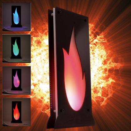
The result is a very impressive gadget, which mounted on a suitable black plastic frame showing internally the shape of a flame, with behind applied a layer of opaque white plexiglass, perfectly simulates the fire and can therefore become an effect for a pub or a bar style gothic or a little ‘dark and, why not, the heart of a fake fireplace. The versatility of the project also allows you to create different shapes from the flame (we’ll see later how), and inserting LEDs into a pumpkin you can get a bright gadget for the Halloween party, where from the holes, flames will spread, illuminating all around with spectacular effects.
Of course, what we will get in this case will not be a real flame made to heat, but it will create an atmosphere of virtual warmth with the charm of the flame and its swaying that on gloomy days we will surely appreciate.
After all, as the “Nomads” sang 50 years ago, “…the fire of a fireplace is not as hot as the morning sun….” so even the real fireplace may not satisfy you….
THE PROJECT
Uses aside, in which we are sure we have little to teach you, let’s see what it is: the system consists of an Arduino Business Card FT1120 that we have programmed with a sketch that can, by importing an appropriate library, to drive the Neopixel LED strips containing a different number of RGB diodes and arranged appropriately to form the classic shape of the flame.
Since the Bi-Card FT1120 is an Arduino-compatible controller, structurally similar to the Leonardo, for the management of Neopixel LEDs we relied on the wide availability of libraries churned out for this purpose by the community of Arduino developers.
Among those available on the Web, to manage the Neopixel strips we chose the popular library Fastled, which we have modified customizing it according to the needs of the project; the choice of this library was dictated by the fact that it has greatly simplified the management of Neopixel LEDs and because among the various demos that integrates offers the flame effect: so with it we have solved most of the software design.
Since the library does not support the control of the number of strips that we needed to draw the shape of the flame (or rather, to illuminate it) we have modified it to manage multiple channels (strips) so not in series; to be exact, we have 5 strips to give the shape of the flame and run differently from each other and the Fastled has been adapted to manage 5 I/O lines of the Arduino board, which are the digital I/O D8, D9, D10, D11 and D12.
So far the Neopixel management; the firmware, however, is also responsible for other tasks and specifically for the reading of two of the buttons on the card, that in the original project of the Business Card were used to activate via USB the web browser opening functions for pointing to the web page of the owner, the opening of the e-mail client and the associated Social Networks. Specifically, we use the e-mail button (we will call it button 1) and the one to access the Twitter profile (we will call it button 2).
Regarding the functions assigned to them by the firmware, they are as follows:
P2 becomes Button 1 and is used both to turn on the system, and when the circuit is running, to change the effect; the button is the one that in the Bi-Card activates the opening of the client for e-mail;
P4 becomes Button 2, which if pressed turns off the light game, bringing the microcontroller to standby; the button is the one to open Social Twitter.
The set can be easily powered from the microUSB connector (which in this circuit is able to carry well over 1 ampere) taking advantage of the fact that the Arduino Business Card has the pads for the standard Arduino headers, among which are those corresponding to +5V and ground.
The Neopixel LEDs that altogether the board must drive are 144 and this number is not random, but it results from a compromise between the desired size for the system, then for the flame, and the characteristics of the products available on the market; in this case we decided to obtain the strips from a roll of Neopixel LEDs marketed by Open Electronics (code 2846-1MNEO144 of www.open-electronics.org) that counts, in fact, 144 neopixel diodes. This is a strip roll containing RGB LEDs addressable high brightness, flexible and weatherproof because it is characterized by degree of protection IP67, this feature, which could be interesting if you want to make a gadget to work outside.
Each individual LED (SMD5050) integrates the control chip. Each chip communicates with the next via a line transferring the information received. The distance between the LEDs is 7 mm and the strip can be cut to each LED, i.e. each LED can be managed individually, but also that from the strip we can make strips of the desired number of Neopixels.
The power supply of the strip is standard 5 Vdc and the maximum absorption with all LEDs lit white at full power is 8.5A, but this condition in our circuit will never come true, because at most we will have an absorption of less than 1.5 amps.
From the roll you have to cut out 5 strips and connect them not randomly, but with a certain order which is what the firmware expects; to be exact we have the following correspondence between the Arduino pin and the number of LEDs:
D8 drives the 27 Neopixel strip;
D9 drives the 31 Neopixel strip;
D10 drives the 41 Neopixel strip;

D11 drives the 28 Neopixel strip;
D12 drives the 17 Neopixel strip.
You can customize the arrangement of RGB LEDs and also the number of those that make up each portion, for example to draw the typical Halloween pumpkin with glowing eyes, but you need to put hands on the firmware and its library.
In terms of firmware, although the Fastled library takes care of most of the tasks, the sketch is still long to be published in full in this article, so we report only an extract in Listing 1 where you can see the “define” of the code.
Listing 1
#define STRIP1_DATA_PIN 8 // define data pins for all 3 LED strips
#define STRIP2_DATA_PIN 9
#define STRIP3_DATA_PIN 10
#define STRIP4_DATA_PIN 11
#define STRIP5_DATA_PIN 12
#define pulseff 5
#define pulsoff 3
#define COLOR_ORDER GRB
#define NUM_LEDS_1 27 // how many LEDs in each strip
#define NUM_LEDS_2 31
#define NUM_LEDS_3 41
#define NUM_LEDS_4 28
#define NUM_LEDS_5 17
#define FRAMES_PER_SECOND 25 // faster or slower burning fire
#define COOLING 55 // Less cooling = taller flames. Default 55, suggested range 20-100
#define SPARKING 50 //Higher chance = more roaring fire. Default 120, suggested range 50-200
#define BRIGHTNESS 125 //Set global brightness here. 0-255
#define FADE 40 //How slowly the LEDs fade to off
In it you can see the instructions that define the number of LEDs that make up the individual strips, which are those to be changed in case you want to change the shape and length of the portions of the LED strip; the current values correspond to the default lengths of the strips shown in the drawing at the top of the page.
In addition, if you want (you can do it safely) add channels and then strip Neopixel than the five provided, you must add the relative define and adapt the sketch, which you can download from our website www.open-electronics.org along with the project files and drawings to get the flame from plexiglass.

FRAME AND ASSEMBLY
The rest is all in the mechanical part, that is to say in the frame, which we have thought of as you can see from the photos proposed in these pages (in particular from Fig. 1): it is a 3 mm thick plexiglass structure made up of:
a slab hollowed out internally according to the shape of the flame which is the most advanced part (measuring 155×360 mm with the base enlarged to 189.4 mm);
a rectangular white plexiglass plate of the same dimensions, applied behind it in direct contact or spaced using 5 or 6 mm spacers (measuring 1 mm less than the front on each side);
a black plexiglass base plate of the same dimensions as the front one, to which the LED strips are applied, gluing them with soft double-sided tape or silicone sealant, as shown in Fig. 2.
The three plates are joined by means of four sets of cylindrical spacer studs and as many 4MA bolts with nut, which in our specific case we chose Allen with cylindrical head, as you can see from the photos of the prototype.

Fig.3
Also in our version, we included a 3D printed enclosure with our 3Drag printer, made of black PLA; it too, like the plexiglass plates, is purchased from Open Electronics. This enclosure was screwed behind the back plate that acts as a support for the Neopixel strips, and has a back cover with two flexible button covers cut out to press on the P1 and P2 buttons on the Business Card (Fig. 3).
As for the connections, you can take a cue from Fig. 4, where you can see the wires used for wiring to the LED strips, which are part of a multicolor strip; note how the wires are stopped by adhesive tape and come out at the rear from a slot in the plate on which the strips are mounted, so as to facilitate the wiring with the board, which regardless of whether or not you choose to equip it with the container printed in 3D, will be placed at the rear in order not to interfere with the rest of the structure, nor with the propagation of light produced by LED Neopixel.

Fig.4
Of course, the type of casing we thought and proposed in these pages from the photos is an idea and one of many possibilities; nothing prevents you from rethinking the structure and even the form, for example, simplifying the whole and composing it of only two rectangular or square plates, one bottom and one front in white plexiglass, which you will then apply the black adhesive film cut out with the shape of the hollowed out flame.
In short, you can let your imagination run wild, because what matters is the electrical wiring; the rest is adapted to your needs.
BOARD PROGRAMMING AND TESTING
As for the programming of the system (the firmware) the sketch is loaded as in any Arduino board, in the sense that it is programmed using the Arduino IDE as if it were a third-party board; to do this you must open the IDE (it must be at least version 1.6.x) and give the menu command Tools>Board>Boards Manager with which you will access the menu that summarizes the available boards, in which you will click on Arduino Leonardo.


At this point, connect the Arduino Bi-Card to the Personal Computer using a cable terminating with the microUSB connector, open the COM assigned to it, being understood that during programming you must not power the board with other voltage sources, otherwise there would be a conflict between the USB power supply and the external one, resulting in damage to the board and or the computer.
Now go to open (File/Open) the sketch downloaded from our website www.open-electronics.org together with the other project files and click on the send button to load it into the memory of the Arduino Business Card.
Once loaded, disconnect the cable from the microUSB socket and the circuit is ready for use; then connect the power supply connector to the microUSB and press Button 1 to turn on the flame: you’ll immediately see the wonderful animation it is capable of, which will be emphasized if the device is turned on in a low-light room.
CONCLUSIONS
Our Neopixel LED flame is an excellent gadget to be used in many situations, easily achievable and fully customizable both under the mechanical aspect (you can change the shape and consequently the arrangement of the LED strips at will), both for what it concerns electronics; in this respect, as mentioned, you can modify the number and quantity of Neopixel strips and respective LEDs by adjusting the sketch.
Good job!
FROM OPEN STORE

Hello – Thanks for sharing this. Can you provide a link t the larger sketch yu referred to (not just the #defines)?
Thanks.
Mike