Getting to know and evaluate the software offer for PCB, in order to choose the best one for our needs.
Designing an electronic board is a considerable and varied effort, both in terms of board design, starting from its functional specs, and in terms of construction. In order to create an integrated board, we have to define all its functions, understand its operational limits, select the most fitting components, choose the circuit topology and then start by creating the single connections. After all this, we can carry out the first tests and check functionalities. The process, as simple as it sounds in its description, is actually very complex. The more complex the board is, the more this becomes true; creating electronic boards can be a long process, sometimes expensive, requiring a lot of experience. In many design fields, even in the electronic field, there are some instruments capable of supporting designers when creating prototypes.
In this article, we will explain in detail what CAD instruments for electronic board design are and how they can be used for creating PCBs. We will focus on the most interesting features and the actual possibilities available, considering the differences between open-source software and proprietary, paid software.
Why CAD?
First of all, let’s start by explaining what a CAD is and how it works. A CAD, meaning Computer Aided Design, is application software used for assisted design on the PC. A CAD is, however, a generic software used for designing, in fact, there are CAD instruments in the architectural and construction field. Designing by using CAD it is not specific of the electronics sector, but it is also common in mechanics (Solid Works and AutoCAD), constructions (AutoCAD), aviation (CATIA), nautical science and medical prosthetics.
Its features are varied and for all of you who are familiar with the concept of IDE, there are obvious similarities. Anyone who wrote code in different programming languages knows very well that an IDE, meaning Integrated Development Environment, is a very useful work instrument capable of making the programmer’s life simpler, for instance by highlighting the structures and the data types, proposing advanced functionalities features of contextual help and so on.
From this perspective, CAD instruments are very similar to IDEs. In fact, thanks to a CAD, we can introduce components in a “standardized” manner; when creating circuits, one of the basic elements proposed is obviously the connection, i.e. a wire.
It is, therefore, a development environment in which we can emulate the presence of actual circuit elements. Everything, once we have completed the topology study, represents the first prototype for the test and verification stage.
Some of the CAD instruments we are going to see are also capable of implementing first tests, and they can even simulate laboratory equipment.
There are therefore different aspects making a CAD a much wiser choice:
- no need, at least in the first stage, to buy physical components;
- the project can be immediately edited;
- we can simulate the circuit’s behavior;
- we can run preliminary tests to check to function.
Of course, as it is often the case when the market offer is varied, there are many different types of these instruments. So, let’s try to understand the main features to guide you in your choice; to this purpose, we can identify the following five main features.
- Immediacy: this is an important aspect because the CAD’s purpose is to make complex instruments easier to use; the user interface must be simple, the icons must be easily recognizable, the menus must be well organized, enclosing all the available instruments in an effective matter.
- Functionality: this means that the software must have all the features making it really useful; for instance, an intuitive user interface, which is easy to learn and memorize. A designer never likes to tentatively browse through menus to look for what he needs.
- Stability. It is crucial, even for the youngest and most innovative CAD projects, to include all the essential tools a project designer needs; a component not included in the libraries or a high number of layers must all be well-supported features.
- Reasonable price: besides free features, it is important to understand what makes the price for a CAD “reasonable”; we can see there are base functionalities, which we are going to describe later in the article, justifying part of the price. The rest is logically connected to the services developed by the companies in order to distinguish themselves from the competition; the fact that supporting add-ons, update packages included in the purchase agreement are worth the software’s price or not, must be decided based on your personal needs.
- Broad library catalogue: any CAD worth of this name includes a series of components. Depending on how big the community is or how well-established the company is, the software will be able to increase its library by quickly supporting all the new electronic components launched every day. Whenever this is not the case, it must be simple and immediate to create a new component or component family, to define a new element of a library, or to create a new library.
Keep in mind that all instruments will have a learning curve to be able to fully take advantage of their qualities, therefore, as much as the software respects the aforementioned features, you will surely have to invest some time to get to know the work environment.
Besides what you are going to read in this article, it is always useful to experiment with different software solutions in order to exactly understand which one is most complete, which one captures to your needs the best, but especially which one you will be able to configure more efficiently in order to optimize your design time.
CAD TYPES
CADs for designing a PCB can be divided into macro categories: open-source and proprietary software. In the first case, we are talking about “open” projects allowing to edit any aspects of the software, therefore allowing the developer to create their own customized version, which can be possibly shared. In the second case, however, you will have to use the software as it is, but you can refer to the company for any concerns, problems and possible features to be integrated in the future; however, the use license will have a price and a relative duration to renew, that you will have to include them in the budget for your project.
It is important to underline that there are actually many different kinds of licenses; in particular, there is purchase license allowing the company to acquire the software and the use licenses, basically configured as a monthly or annual fee. In the second case, however, the multi-license option, which is the possibility to use the software owned different machines, might be more economically convenient.
There is also a more “functional” division, distinguishing between “off-line” and “online”. One of the most useful features all computer users have tested in the latest years in a more and more pervasive way is the cloud: the possibility to save data that becomes accessible through a single platform on more machines simultaneously is definitely convenient, especially because it enables collaborative projects. PCB CADs, in some cases, can implement this feature. In particular, when we use online editors, it is possible to keep a history of your projects (to make available to third parties in some cases) and take advantage of a “virtual” space allowing you to free estate on your hard drive.
The best-paid software
There are so many software options available on the market for programming printed circuits, however, the most popular, complete and used in the professional and enterprise sector at the moment are three: Altium, Eagle and OrCad.
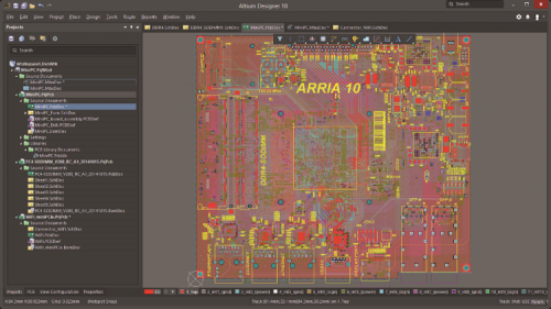
These solutions are probably too expensive for a beginner designer and even more so for a hobbyist. However, companies can certainly take this kind of software solutions into consideration without much trouble. The main thing to understand is that, regardless of license price, all the functionalities included in the software are what makes it more or less interesting. Altium Designer is considered to be the most complete and versatile CAD development environment for PCBs currently available on the market. We cannot give you an unambiguous indication regarding license costs because Altium has different licenses according to the features you want to include. Keep in mind that you won’t pay less than a four-figure price to bring it home!
This is a solution typically bought by big companies working on many projects at a time, with very experienced designers with a long career behind them. This solution is very rarely used by self-workers, makers and freelancers. These types of designers typically choose other solutions, maybe even paid ones, although with a definitely lower price tag for a license. In particular, Eagle and OrCAD represent two alternatives currently available on the market with definitely lower costs.
The former recently changed hands, becoming one of the leading software products from Autodesk, already famous for one of the most used software in constructions prototyping, which is AutoCAD.
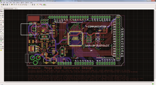
Eagle has always been distinguishing itself for simplicity of use and great versatility. Right off the bat, it catered to a wide professional audience for the support they offer. It has been widely used in several open hardware projects, among which Arduino itself, and many electronics components suppliers provide updated libraries for supporting their components. In terms of the license, Eagle proposes a yearly subscription for around $100, while before the recent acquisition the software was available at a one-time price, forever.
Although it can be still used in its trial version, this one is not allowed to design multilayer PCBs nor to use advanced features.
OrCAD is a completely composite software solution, which doesn’t just include CAD but also other simulators and features, such as Capture, PSpice, PCB Designer and PCB SI. The library editor is configured as a software per se, still included within the package. In terms of price, OrCAD is slightly higher than Eagle but also provides different solutions, just like Altium. Besides, OrCAD is also distributed under an “Educational license”, and extremely popular formula which makes it easier to access the software by students and training subjects.
There are also way cheaper solutions, such as DipTrace. It is a software which complete license is offered at just above €900 and it effectively is an excellent instrument, especially for those who just started out designing boards based on integrated circuits. The license systems used by DipTrace is extremely versatile because for most projects, especially at the beginning, you will absolutely be able to do without a full license.
Other very interesting solutions among the paid ones are:
- Ultiboard, a software solution by National Instruments, although not totally “free”; in fact, in order to use it, you initially have to access a trial although complete version, and then request a quote for a license. Its strength is in the complete integration with Multisim (advanced teaching instruments for SPICE simulation), making the combined solution by National Instruments a really powerful tool. Keep in mind that this company is a leader in the measurement instruments industry for every sector, from electronics to telecommunications, therefore the product meets those standards.
- SolidWorks PCB: an instrument capable of perfectly interact with other tools by SolidWorks and one that can brilliantly enrich the completeness of a PCB project with 3-D modelling. The advantages of such features are obvious, from encumbrance study to custom covers and enclosures modelling; in many PCB CADs, those features are not natively supported.
- CircuitStudio is an emerging CAD solution integrating 3-D modelling instruments and proposing, among other things, a perfect retro-compatibility and portability with projects developed both in Altium and in Eagle.
Other proprietary solutions are: Mentor Graphics Xpedition, Tina, Proteus Design Suite, Circuit Wizard, AutoTrax, Zurken CR-8000, Pulsonix, EdWinXP, CADSTAR, OSMOND PCB, COMET CAD, VUTRAX, CIRCAD.
Upverter’s license system is very interesting, somewhat similar to Eagle, allowing to use a base version free of charge and combining a tiered license system based on the features required by the user, so that you are able to customize them based not only own single, specific needs but also based on the size of the interested company.

The best free solutions
In spite of the multitude of paid solutions, there are valid open alternatives that are freely available.
EasyEDA is an open, online-based solution, allowing to create your project in an extremely complete way. It allows you to work on the circuit diagram, but also to take care of the layout and routing; after this step, you will also be able to simulate the circuit’s behaviour when a signal is applied. It is, therefore, a very intuitive software solution, which will bring you from the starting idea to the creation of Gerber files.
Just like other software solutions, DipTrace also calls for different modules based on functionalities. It can be used to create diagrams but also to take advantage of the dedicated module to create the PCB layout.
The editor manages multiple layers, basically allowing to create multilevel components and hierarchical diagrams. In short, you can use dedicated circuit diagrams for the single portions or subsections of the circuit itself. This functionality is particularly convenient, especially when you are designing board that are going to integrate several similar components. For instance, suppose you’re working on a control board for a 3-D printer; you will certainly have at least four distinct motors, but you will surely use the same motor model, which means you will need the same driver model for each motor. Of course, being able to replicate the conditioning circuits of the driver or the number of components you are going to actually integrate is a noticeable advantage.
DipTrace allows exporting the output of these projects with modules dedicated to simulation, which allows for a complete analysis, at least at a preliminary stage, of the design solution. Those features are a “no-brainer” in professional-grade proprietary software such as Altium, but not as much for open solutions; that is why DipTrace is above the rest.
Diptrace also has the ability to create component libraries using a dedicated tool. Other very interesting, three solutions are listed below.
- KiCAD, which is probably the most famous and popular open-source solution currently available, is also supported by a community of hundreds of thousands of users all over the word; KiCAD is a project including really everything a designer need and although it might appear clunky to use at times, KiCAD manages to synthesize, in just a few steps, circuit diagrams and circuit routing even in extremely complex cases.
- PCB Artist, extremely complete and equipped with a library including well over 500,000 components.
- PCBWeb, very interesting because it integrates the Digi-Key catalogue, thus providing the designer with useful support in choosing the most readily available components, optimizing the list part and, as a consequence, creation times. Among the other free solutions with an integrated part list, we also have to mention Pad2Pad.
- XCircuit, online freely available with a series of related tutorials making diagram modelling software easy and immediate to learn. The base features mentioned so far are all included and this can be considered as a valid instrument, especially for beginners.
- DesignSpark, somehow similar to PCBWeb, but linked to RS Components, DesignSpark had some really valuable features. For instance, it supports designers in creating integrated circuits up to 1m x 1m max, besides guaranteeing format compatibility for all the files managed by the main preparatory solutions.
- Among the free solutions, we also mentioned ZenitPCB, largely considered to be in extremely intuitive solutions, allowing for very quick routing.
The open license software ecosystem also includes FreePCB, PCB123, CUSPICE, ExpressPCB, EasyEDA, tinyCAD. Very usable to understand the fundamentals of routing and also the influence of each track in the various connections is Microstrip Impedance Calculator, and extremely easy to use application which, starting from the geometrical dimensions of the connection, and inserting parameters like dielectric constant of the material composing the track, is capable of telling the designer the resistance components introduced.
A special mention for Fritzing, which started off as an emulation project of physical components, currently turned into an incredibly complete teaching instrument used by the Arduino community and by makers in general. After getting all the features related to routing and Gerber files export, Fritzing today can also manage the programming for the Arduino family microcontroller for us.
Many of the freely available solutions are valuable especially because they combine PCB creation using CAD to their services for production and circulation of PCBs. This possibility, as always, as for anything else, has some pros and cons of. In fact, depending on the company, “locking” the supplier of the hardware produced might not be the best choice. However, as a general rule, the possibility to provide the layout and the Gerber files in input to the PCB production and mounting service offering the best price is undoubtedly an advantage. Especially in terms of shipping times, which can be over two workweeks in some cases.
As for all open source projects, of course, we must also take into consideration the so-called Community-Driven solutions. In fact, in most cases, the development model used is not the same of some Linux distributions, for instance, Ubuntu. This operating system has a company behind it, Canonical, which takes care of keeping the project alive, continuously developing it, protecting it in terms of possible bugs, especially in terms of security, and at the same time they keep it free to access by users all over the world.
All those willing to create packages or solutions, or even patches act as contributors to the operating system project.
In those cases, where there is only the community to back up the project, there is of course much more volatility in terms of balance and life of the project itself. This is not compatible with the needs of a professional audience and companies in general, which need stability, continued technical support, certainty and reliability. A company can hardly base its business on open solutions alone. At least for the so-called Core Business.
Automatic or manual?
Almost all the solutions we have introduced have a constant characteristic: there are features that can be executed automatically or manually. We are talking, for the most part, of routing and Design Rule Check. First of all, circuit and component placement is an operation that you will have to carry out yourself; there is no routine capable of efficiently making the process automatic. Dividing analogue and digital areas, isolation and thermal dissipation are just a few of the cases requiring your total and careful attention. The routing, which is the pin by pin connection, is an operation that can be carried out by using, where available, a motor taking care of this task automatically. It is a very useful feature, although not always effective because too often, the so-called “Auto-Routing” carries out its task in a non-optimized way. Sometimes the tracks become longer than necessary, other times they are too near to some other which, for functional reasons, should be farther away. Our suggestion is to use the automatic routing feature with caution. You should only use it as a first step and then you should optimize the tracks yourself, possibly one at a time. Yes, this job takes a lot of patience. The ideal case would be having a CAD capable of defining restrictions when executing the auto-routing, i.e. length limit for some tracks, their geometry, distance from other tracks (for instance in order to guarantee electric isolation) and so on.
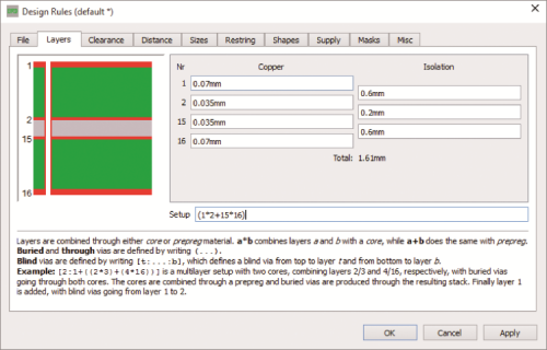
The second feature (Rule Check) is about verifying the rules of the project. Some engines are not perfect and might “overlook” something, for instance, the analogue filter routing being made with only 90° tracks. This is one of the main cautions for a designer. Each track, just like each path, must be defined from a dimensional perspective. Especially because there is a difference between the track used for powering a power circuit and a track used for digital connections. The paths, depending on their function, must be more or less large or more or less distant from one another. Although, at least at the beginning, it might be useful to set all the dimensional criteria for each track, and each layer, it is highly recommended to carefully check after every routing.
After the design process is complete, you should move onto the next steps which are manufacturing and assembly. The first step of PCB assembly is applying a solder paste to the printed circuit board, that can be done with a stencil printing machine. After applying the solder paste the whole process continues with the pick and place machine that will place the electronics components on the circuit board. Next, you need to make sure that the components won’t fall off the PCB. For this, a reflow oven will do the job. This reflow oven consists of a series of heaters which will heat the board to temperatures around 250 degrees Celsius, depending on the number of heating zones, make sure you choose a reliable model for reflow soldering. Once the components are successfully placed and soldered on the PCB, you can inspect it in 3 ways: manual, using x-ray and automatic by using an AOI machine.
Conclusions
We have seen the main features of CADs for PCB programming. Some of the solutions proposed will surely meet your needs. We suggest to carefully read the technical specs of each software solution you are going to evaluate: not all CADs are equal and not all software features are equally useful. We believe that after reading this article you might have a better idea of the subject. Anyway, we hope our message is clear, which is that the perfect CAD does not exist; each one is a compromise and only practice will tell you if that’s the one you are looking for.
Enjoy!
