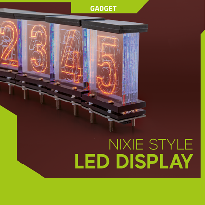

We pick up the fascinating Nixie tubes through displays based on packages of laser-engraved plexiglass plates, illuminated by Neopixel LEDs.
For those born in the era of solid-state displays, be they LED, 7-segment, dot-matrix, or even liquid crystal, it is difficult to imagine how text and numbers were displayed before their advent; Well, those who have around half a century certainly remember that the first electronic displays used were those based on “nixie valves”, i.e. electronic tubes (which is improper to call thermionic valves since this term indicated vacuum tubes capable of opening, closing or modulating the current flow) containing grid electrodes shaped like the characters to be represented, which became bright thanks to the thermionic emission and the light obtained by driving it through a sufficiently intense electric field. These characters, i.e. their respective filaments, were as many as the number of characters to be shown for each digit (and therefore for each tube) and were physically arranged – inside the glass tube – all lined up one behind the other, with the less bulky ones in front for reasons of visibility of those that were behind.
With the project of these pages we want to dust off the charm of the nixie through a circuit capable of combining the principle of displaying those components from the unquestionable charm with the latest technology, simulating the way to build the characters of nixie through modern Neopixel LEDs and plexiglass plates engraved in such a way as to create paths for light, visible when viewed from the front.
PROJECT
So let’s see what we propose in these pages consists of, which in essence is a modular system consisting of a certain number of digits, i.e. digits, each of which is a basic module consisting of 10 laser-engraved plexiglass plates with the shape of a number, mounted side by side on a frame (packed, if you prefer …) at the base of which there is a printed circuit that houses a certain number of miniature Neopixel LEDs that project their light in the direction of the length, making the figure illuminate engraved in plexiglass. Each plate is illuminated from below (ie from one of the narrow faces) by means of two LEDs; this quantity is not arbitrary but it was chosen because we have seen that with a single LED the number 1 lit up satisfactorily, but the larger ones such as 8 would have been not very clear and in any case, proportionally, less bright than smaller ones. This concept is also relevant because large numbers such as 6, 8, 9, for example, are placed behind the others and therefore, due to the inevitable absorption losses resulting from the postposition with respect to the small number plates, would lose visibility.
The composition proposed in this article has six digits with which we have realized the display for a digital clock, properly driving the circuits containing Neopixel LEDs; the latter are connected in cascade and for this purpose have been designed to be placed side by side and connected to each other by means of jumpers of copper wire.
To drive the cascade is a control board that incorporates a WiFi module with which, if there is a wireless network, we can connect to the Internet and in particular to an NTP (NETWORK TIME PROTOCOL) service that allows you to have the exact time constantly updated, whose data will then be processed and sent to the displays.
The system is therefore based on an ESP8266 mounted on a simple board that integrates the power stage necessary to obtain the 3.3V needed by the module, starting from an input voltage of 5V (needed instead for Neopixel LEDs). The WiFi module connects to the site us.pool.ntp.org in UDP from which it extracts the time and displays it on the Nixie LED display.
Therefore, the electronics consists of two types of boards: the control board, which is unique, and the boards containing the Neopixel LEDs that are the basis of the displays; the latter are one for each digit of the display. In our case, since we are proposing the realization of a clock with display of hours, minutes and seconds, there are 6 digits and as many LED boards (Neopixel boards).
Each digit module appears as shown by the rendering in Fig. 1. and is formed by a printed circuit with the components side of the SMD Neopixel LEDs arranged so as to project light to the base of their respective plates, each of which, as you will see later, is shaped at the bottom with notches aimed at the best possible optical coupling and therefore arranged so as to face each on a LED.

Fig. 1
BASIC SHEET
Also called control board, is the one that generates the data to be sent to the cascade of Neopixel boards and is generally a circuit equipped with a communication bus compatible with the Neopixel standard and therefore composed of a data wire, a common ground wire to the power supply and a third that carries the positive power supply. The same circuit must be equipped with a microprocessor (or better, a microcontroller) able to generate data in serial form according to the Neopixel protocol.
In our case it is a board (you can see it in Fig. 2) on which there is a WiFi module based on ESP8266 and therefore equipped with an embedded microcontroller programmable to connect to the Internet via a WiFi access point point pointing to a site that provides the updated time signal, extract the information and prepare the corresponding data in the form of packets to be sent serially along the data channel.

Fig. 2
So the board that produces and sends the data to the chain of display boards and modules does not generate the data itself, but draws it from a website using the WiFi link, then extracting the significant information and preparing with it the packets to be sent serially along the data channel to the displays.
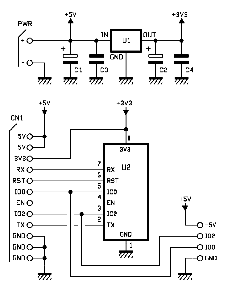
The circuit diagram of the board, shown in these pages, shows the WiFi module with the initials U2; this device is interfaced externally through its own serial port accessible from connector CN1, which also shows all other significant pins.
As you can see from the diagram, the connector (pin-strip) that drives the cascade of display boards is composed of two terminal blocks that carry, in addition to +5V and common ground, the IO0 and IO2 lines (two GPIO of U2 module) that carry data; to be exact, in our application we send data to the displays through IO2, but the other could be used to create a second Neopixel channel or to connect for example a button to change the light effect.
The same contacts of the terminal blocks are reported on CN1, where also TX and RX of the UART arrive, reset and more.

Fig.3
The entire circuit is powered with 5Vdc stabilized, taken from any power supply (switching or linear) as long as it has a stabilized output, properly filtered by capacitors C1 and C3 placed in parallel to the power supply line; the same 5V are brought to the CN1 connector and to the output terminal blocks, as well as to the input of the regulator U1 (an LD1117S33TR) which is a three-terminal LDO used to obtain a stabilized voltage of 3.3 volts (filtered by C2 and C4) necessary to the module with ESP8266 to work properly. Note that the 3.3V is only used to power the ESP8266 module, while the Neopixel LED boards are powered with 5V taken directly from the input terminal. Pay particular attention to the power supply used, which must be strictly 5V.
Regarding the ESP8266 module firmware, it adopts the library is by Connor Nishijima modified for our Neopixel modules; moreover it includes all the portion of code needed to establish the connection in UDP (User Datagram Protocol) with the desired web site, that is the one from which to draw the time data, which specifically is us.pool.ntp.org.
It is worth noting that the library we “elaborated” allows you to display numbers with different effects: for example you can light a digit with one color and the others with another, much softer color. When the number on each digit changes, you can choose how this should happen: for example you can have the fading effect, or the flip (all digits are lit in sequence and then only the desired one is lit).
And of course you can not miss the nixie effect, which consists of lighting the number to be displayed in a beautiful orange color typical of nixie and the other digits (i.e. the remaining plexiglass plates) of the digit in a blue color but very soft light, thus obtaining an appearance like that of a glass tube containing an illuminated filament, around which is created a sort of blue aura simulating the reflections in the glass envelope.
DISPLAY MODULES
Each elementary display, i.e., a digit, is composed of 10 laser-etched panels packed together and properly constrained, as you see in Fig. 4, which shows the rendering of the digit viewed from the side, with the juxtaposed plates highlighted.

Fig.4
Each panel is illuminated at the base by two miniature Neopixel LEDs (Open Electronics code LED Neopixel WS2812B-2427) and managed by an Arduino or compatible board, using a special library.
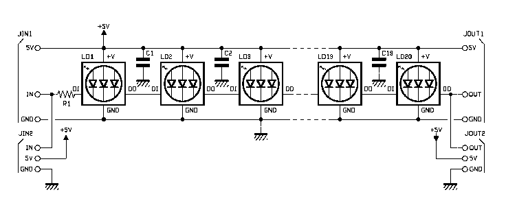
In these pages you will find the wiring diagram of the board, which is basically composed of two rows of three contacts each in parallel for the inputs, shown on the long side than on the short one and as many for the outputs, similarly arranged; the input bus consists of the data wire coming from IO2 of the control board and the power supply including the ground, in common with the data one. The data channel enters in the DI contact of the first Neopixel LED through a 470 ohm resistor and from the DO pin the repeated data string is taken, because a feature of Neopixel LEDs is that internally they have a controller chip that can read the received serial data string and repeat it so that it reaches the other elements connected in cascade, executing only the data part, that is the command, identified by the address corresponding to its own.
So the 20 LEDs of each digit board are all connected in parallel for what concerns the power supply and in cascade for what concerns the data; the last LED of the board has the DO output connected to the output pin rows, so that the data can reach the next board, where it will have a similar effect, i.e. only the relevant commands will be executed by each LED.
SYSTEM PROGRAMMING
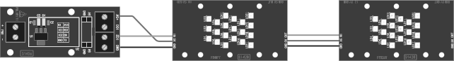
The module can be programmed using the Arduino IDE as if it were a third party board, but requires some small precaution, or to be able to program it, in addition to connecting the module through a TTL/USB converter of those able to provide power to 3.3Vdc, it is necessary, to send the module in programming, place IO0 (GPIO) to ground. For this reason we recommend the use of a circuit designed specifically for this purpose, which is the debugger dedicated to ESP8266, available online from Open Electronics (the product page is www.open-electronics.org) which has jumpers in parallel to the pins of the strip, easily jumpable with jumpers PC step 2.54 mm. This circuit acts as a base and houses the module based on ESP8266, which therefore does not need to be connected by wires and can be mounted on it without the risk of making a wrong connection and damaging it. Based on the USB-TTL CH340G conversion chip, this device allows you to upload firmware or Arduino code to the ESP8266 WiFi module. On the adapter there is, in addition to the 2×4 pin female connector dedicated to the ESP8266, also a reset button, a 3.3 volt voltage regulator and 2×4 pin male connector with: 3V3, GND, RST, IO0, IO1, EN, TXD and RXD.
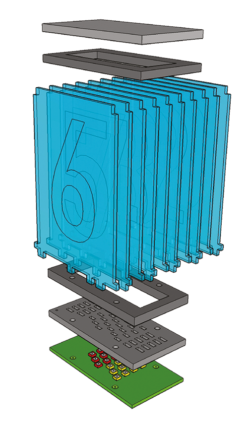
Fig.5
Once applied the module to the debugger, to proceed with the programming you must first download the ESP8266 Debugger drivers (the drivers are those of the Silicon Labs USB transceiver, reachable on the web at the link https://www.silabs.com/products/development-tools/software/usb-to-uart-bridge-vcp-drivers) then open the Arduino IDE and install the third-party driver using the menu command Tools>Boards>Boards Manager; with this command you access the corresponding window.
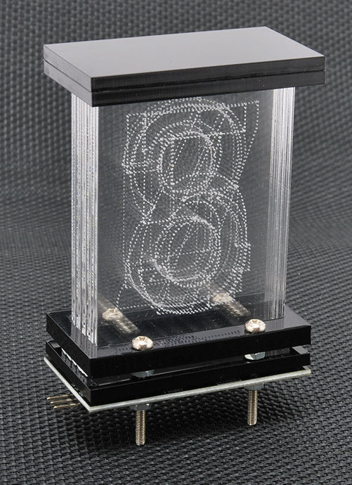
Fig.6
Remember, however, that after downloading the drivers in the destination folder, you will see them in Boards Manager only if you have previously defined the relative search path; this is done by giving, from the File menu, the Settings command, then writing in the Additional Board Manager URL box the path where the files are located (Fig. 8) and confirming with a click on the OK button, which brings you back to the main window of the Arduino IDE.
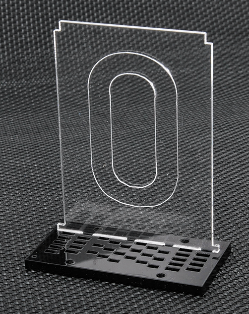
Fig.7
Once the board is installed, you can select it and then choose the COM port ESP8266 Flasher and Programmer + ESP8266 WiFi Serial Transceiver module; connect to it by setting the baud-rate to 115200.

Fig.8
Now open (File/Open) the sketch downloaded from our site www.open-electronics.org together with the other project files and click on the send button to load it into the memory of the module; it is understood that in order to successfully connect to the WiFi network you must have modified the sketch by inserting, instead of the default values of SSID, network name and so on, the parameters of the wireless network to which the module with ESP8266 will connect. In order to display the Italian time you must set the time zone with this instruction TIME_OFFSET = 2.
At this point, unplug the USB cable, disconnect the module from the Flasher (programmer) and mount it on its board, which you must have already wired with three wires to the first display board, which will then replicate it to the second, third etc..
Once you have verified the connections of the whole, power the base board and if all goes well, just the time to establish the Internet connection and you will see the exact time appear on the display.
If everything works as expected, you can consider your clock ready to be mounted in a suitable container, which you can choose as you like and position as you see fit; just remember that the WiFi module must be able to receive and transmit radio waves, so if you choose a metal container you will have to make an opening on one of its walls to allow the module based on ESP8266 to look out.
DISPLAY MODULE Components List:
LD1 ÷ LD20: WS2812B-2427 neopixel LED
C1 ÷ C19: 100 nF ceramic0 (0603)
R1: 470 ohm (0603)
Various:
– 3-way male pin strip straight / 90 °
– 3-way straight female pin strip / 90°
BASE CARD Component List:
C1: 100 nF ceramic (0603)
C2: 100 nF ceramic (0603)
C3, C4: 10 µF 6.3 VL tantalum (B)
U1: LD1117S33TR
U2: ESP8266
Various:
– 2×6-way male strip
– 2×4-way female strip
– 2-way terminal 5.08mm pitch (3 pcs.)
– Printed circuit S1456 (60×26 mm)
CONCLUSIONS
Well, that’s it. We proposed a project that allowed us to bring back the theory of operation of electronic displays used in the era of vacuum tubes, namely the Nixie, simulating such displays with an optical structure where Neopixel LEDs illuminate a package of colored plates where the light is propagated transversely through laser engraved grooves.
The display is modular and can be composed of many more digits and driven even with data other than time: it depends on how you set the firmware, which is a modifiable basis for generating data locally, instead of drawing it from the web.
FROM OPEN STORE
