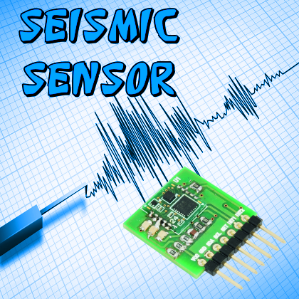
Let’s test the D7S by Omron, the world’s smallest seismic transducer, and create a seismograph capable of a sensitivity and an accuracy that are comparable to the ones found in professional tools.
Each day, thousands of earthquakes occur on our planet, but most of them cannot be perceived by the population (as they may only be detected by the tools) and luckily only a small part of them determines seismic waves that are strong enough to be perceived by men, and even less of them are able to cause significant damages.
Earthquakes have different origins, but the most plausible reason for them lies in the plate tectonics theory: according to it, the earth was originally formed by a single continent (which would explain why the same animal species may be found in distant, separated continents) that divided itself in the five ones we see today. Technically, we are talking about the “continental drift”, and it has been ascertained that the continents still move today. When the continuous and imperceptible movement of the plates suddenly stops, and energy and tension are accumulated in certain zones for decades or even centuries, at a certain point the tensile strength is exceeded and all the accumulated energy is released in a matter of a few seconds, thus generating a sudden shifting of the rock mass involved, and consequently originating the phenomenon known as earthquake by people and scholars. Even the igneous activity under the earth’s crust is connected to earthquakes.
The detection of the seismic activity, that was once typically carried out by means of electro-mechanical tools called seismographs (and consisting in a stylus mounted on a pendulum, connected to ground, and capable of drawing oscillations that are equal to the strength of the ground motion), in recent times has been successfully entrusted to electronics, thanks to existence of sensors such as the MEMS, that are capable of detecting accelerations on the three axes, with extreme accuracy. Such sensors have enabled the creation of electronic seismographs that we may consider as “solid-state ones”, even though they are based on processors that integrate components that are subjected to micromotion.
The project we are describing in this article is based on a similar sensor and, more specifically, on an Omron component: we designed a ready-to-use breakout board for it, an ideal one for the purpose of prototyping applications and experimenting.

[bctt tweet=”#D7S by @OmronEurope, the world’s smallest #seismic transducer, and create a #seismograph ” username=”OpenElectronics”]
THE D7S SENSOR
The device presented here is the world’s smallest seismic sensor to date, it is manufactured by Omron and is signed D7S. One of its most important features is that it signals – by means of the INT1 pin – seismic events that could have devastating effects on electronic equipment; for example, such a function allows to turn off the said equipment, before the vibrations may actually cause such damages. It is essential to safeguard the machinery in order to be able to still have – after a seismic event – operating devices, in order to prevent further damaging events. By the way, the warning that may be obtained from the INT1 contact could be used in order to activate alarms and – why not – to activate some mechanical protection for the measuring tools and for the places that are hosting them.
The signals emitted by the sensor are two: shutoff and ground collapse. The first situation occurs if the earthquake is deemed of an intensity equal to or greater than 5, according to the JMA’s (Japan Meteorological Agency) seismic intensity scale, and if certain conditions – as defined by JEWA (Japan Electrolyzed Water Association standard JWA) as for the JWDS 0007 standard, appendix 2- are met. The second situation occurs if the ground suffers an inclination of about 20°.
The sensor also has an internal memory that stores the data concerning the five most recent earthquakes saved, and the five greatest ones, in addition – of course – to all the configuration settings.
The D7S is composed of a three-axis accelerometer, only two of them are used during the detection of an earthquake, and may be selected by both the user and automatically, with respect to the sensor’s inclination. The presence of a I²C bus enables the modification of the sensor’s settings, or to read the data concerning the earthquakes: this may be carried out by any microcontroller supplied with the abovesaid bus, and from Arduino as well. Overall, the D7S sensor is supplied with three function pins; two of them (INT1 and INT2) are signal pins and the third one (SET) is a line used in order to modify the operating state.
Before using the sensor it is necessary to carry out the initial installation procedure, that is to say that the sensor has to detect the offsets for the selected axes, and to save their values to the internal memory; such offsets will be used in order to distinguish the collapsed condition, so to compare them with the current ones when detecting the seismic event.
After the initial installation, the sensor will enter the standby mode until an earthquake starts, when the calculation of the data concerning the seismic event starts; it remains in such a state until it deems the earthquake has ended. At this stage, the internal memory is updated with the recently measured data.
Each time it is powered, the sensor is brought to the offset detection mode, and it determines if the collapse condition has been met and, if so, it alters the logical condition of the INT1 pin, by setting it to the low level. If the condition is not met, the sensor enters the standby mode and the earthquake detection cycle starts.
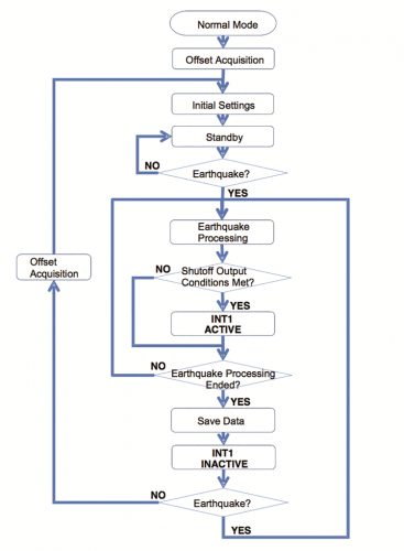
It is good to specify that the verification of the collapse condition does not occur only when turning on the sensor, but every time the sensor enters the standby mode; it is still possible, in fact, to force the control of the collapsed condition by bringing the sensor to the offset acquisition mode.
The data calculated by the sensor for each seismic event includes the PGA (Peak Ground Acceleration), the SI (Spectral Intensity) and the average environmental temperature at which the event occurred. During the calculation, that is to say, during the earthquake, it is possible to read the instantaneous value of PGA and SI, by accessing some specific registers.
Inside of the sensor, a self-diagnostic function has been implemented: it is very useful in order to verify if the D7S correctly operates, but it must be manually activated by writing a register, by means of the I²C bus. For each offset acquisition, the sensor automatically defines if the operation was successful, otherwise, it updates a specific register, and consequently warns of the malfunction.
The sensor’s functional pins are INT1, INT2, and SET: the first one corresponds (as already pointed out) to the signalling of the shutoff and collapse conditions, while INT2 enables us to know whether the sensor is in standby mode, if it is in the earthquake detection mode, if it is acquiring the offsets or if the self-diagnostics function has been activated.
SET, the last pin, enables to bring the sensor – by means of an external pulse – to the initial installation mode, and without having to resort to using the I²C bus.
When the INT1 pin is brought to the low logical level by a shutoff or collapse event, the default value – that is to say the logical 1 – may only be restored by reading the EVENT register (please see the next paragraph), by carrying out the initial installation procedure, or by switching off the sensor.

THE INTERNAL MEMORY
In order to use the D7S sensor, it is needed to know how to program the main configuration parameters and the location of the data calculated by the sensor for each earthquake as well.
The internal memory is configured in 8-bit registers that are addressable by 16-bit addresses. Therefore, by using the Arduino Wire library, for example, it is needed to send the address’ most significant 8 bits, followed by the less significant 8 bits.
Not all of the registers may be accessed, and the manufacturer explicitly declares that you have to pay attention not to access the ones whose access is forbidden, in order to prevent compromising the proper functioning of the sensor itself.
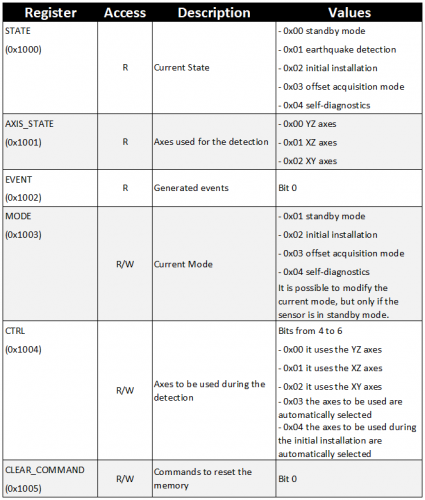
The first three registers to be found in the memory are STATE, AXIS_STATE, and EVENT (they have read-only access); they include the information concerning the sensor’s current state and its current configurations: in its less significant bits, the STATE register contains the state, the AXIS_STATE register is composed of 2 bits in which the axes used for the detections are indicated, while the EVENT register is composed of 4 bits, each one related to a possible event that may occur.
The three following registers are MODE, CTRL, and CLEAR_COMMAND, they may be accessed for both reading and writing and they enable the modification of the sensor’s behaviour: the first register, MODE, enables to change the sensor’s state, the following one, CTRL, enables the selection of the axes to be used and the shutoff threshold, while CLEAR_COMMAND enables – by bringing its bits to 1 – to reset specific memory portions.
Table 1 synthetically shows all the configuration registers and all the values that they make take.
In the registers from the 0x2000 address to the 0x2003 one, instant information concerning the seismic event in progress may be found (if the sensor is in standby mode, the registers are reset) and they are so divided: the first two registers, respectively 0x2000 and 0x2001, contain the SI value divided in an upper and lower part, while in the remaining registers, 0x2002 and 0x02003, the PGA value is found, also divided in an upper and lower part.
Afterward, ten register blocks are found, located from the 0x30XX address to the 0x39XX one, and they contain the data concerning the earthquakes: the first five ones correspond to the last five seismic events saved, while the last five ones are the earthquakes having a greater intensity.
All the blocks have been divided, as shown in Table 2, in which the first six registers correspond to the offset information, two registers contain the temperature at which the seismic event occurred, two registers contain the SI value and, finally, two registers contain the PGA value that has been saved.
table2
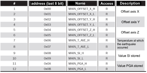
The address of a specific register must be built by adding the block address to the register’s address inside of the block.
Finally, there are register blocks related to the information regarding the initial installation, the last saved offsets, and the self-diagnostics. These pieces of data are not strictly related to the application, therefore we invite those who are interested in them to refer to the D7S datasheet.
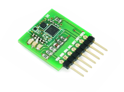
OUR BOARD
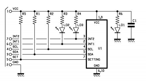
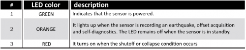
The project we propose here is the one of a seismograph, based on a breakout board, on which an integrated sensor is found; the board makes its communication bus accessible, via convenient pin-strips, so to considerably simplify the usage of the sensor and the integration with existing equipment as well. On the connector, we find the SDA, SCL, SET, INT1 and INT2 pins of the D7S, each one provided with appropriate pull-up resistors. Moreover, we decided to add three LEDs: one is connected to the power source and enables to verify the sensor’s supply voltage, while the other two ones are applied to the INT1 and INT2 pins. The function of the three LED is described in Table 3.
table3
The SET pin may be easily connected to a button, without having to worry about the pull-up resistor, since it has been already prepared in the breakout board, and it may be used in order to bring the sensor to the initial installation mode, simply by pressing it and consequently avoiding the usage of the I²C bus. The connection with Arduino is also a very straightforward one, in fact you will simply have to connect the sensor’s power pins (VCC and GND) to Arduino’s 5V and GND pins, and the SDA and SCL pins (as for Arduino UNO, the pins assigned to the I²C bus are respectively A4 and A5).
Arduino also enables the management of the interrupts; this is a very useful function to be coupled with the sensor shown here since it enables an instantaneous reaction to the events generated by the D7S. In order to use it, it is enough to connect Arduino’s pins 2 and 3 to the INT1 and INT2 pins, and to record the ISR’s (Interrupt Service Routine) execution on pin 2, when the FALLING event (that is to say, the transition from a high logical value to a low one) occurs, while as for pin 3 it has to be recorded when the CHANGE event (it concerns both logical transitions: from high to low and from low to high) occurs.
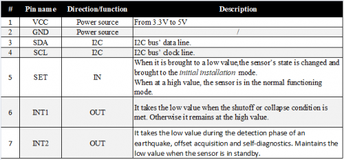
In Table 4, the pinout of the breakout board’s connector is specified (): the first group is formed by the power pins, the second one by the I²C bus’ pins, while the last three are the sensor’s operating pins.
table4
The relevant connections are illustrated in the figure, that shows the complete hardware as for this project; its wiring is simply carried out by means of jumpers on the displayed circuit.

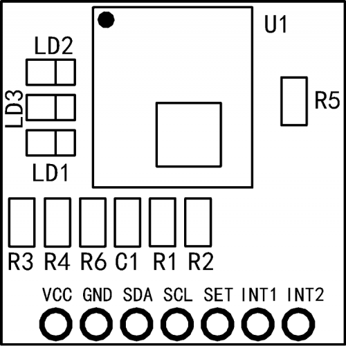
As regards the breakout board, it is possible to create it by yourself, by referring to the assembly diagram shown in these pages: once the PCB has been etched and drilled, please arrange all the components, starting from the D7S integrated circuit, and please respect the direction indicated by the assembly diagram. Given that these are SMD components, a certain accuracy is needed, in addition to the usage of a soldering iron with an extra-fine tip and a maximum power of 20W, of a 0.5mm diameter solder wire, of some flux paste and of a magnifying glass, so to verify the solderings and possible short-circuits among close pads.
In order that the sensor may accurately detect the earthquakes, it is opportune that the printed circuit board is firmly fastened to a structure that is rigidly anchored to the building’s floor, or to a concrete base, fixed to the ground, or to a metal clamp, fastened to the wall; please avoid inserting it by means of the pin-strip (since the mechanical anchoring is not firm enough), but possibly connect the board by means of wires.
Components List:
C1: 100 nF (0805) ceramic capacitor
R1, R2, R5: 10 kohm (0805)
R3, R4, R6: 470 ohm (0805)
U1: D7S-A0001
LD1: green LED (0805)
LD2: red LED (0805)
LD3: yellow LED (0805)
THE ARDUINO LIBRARY FOR SEISMIC SENSOR
We developed a library, so to enable the usage of the sensor via Arduino, and without having to directly manage the registers by means of the I²C bus and of the Wire library. The library enables both the modification of the configuration and the reading of the data concerning the earthquakes, from the sensor’s memory; it also deals with the management of the interrupt events that are generated by the D7S sensor; its usage is shown in Listing 2. Listing 1 shows how to access the sensor’s internal memory, so to collect the data concerning the last five earthquakes recorded. When in the setup function, it is needed to execute a call to the begin() method, that initializes the communication to the sensor. Before starting to send commands to the sensor, it is needed to wait for the D7S to be ready, that is to say, that it is in standby mode. At this stage, it’s possible to access the sensor’s memory, by using the getLastestSI(index), getLastestPGA(index), getLastestTemperature(index) method, in which “index” points to the index of the earthquake whose data we want to collect (the saved earthquakes are five, therefore the index may range from 0 to 4). The library also implements these equivalent methods, in order to access the data concerning the five earthquakes having the greatest intensity that have been stored in the memory: getRankedSI(index), getRankedPGA(index), getRankedTemperature(index).
listing1
#include <D7S.h>
void setup() {
Serial.begin(9600);
while (!Serial)
;
//Initialize communication with the D7S sensor.
Serial.print(“Starting D7S communications (it may take some time)...”);
D7S.begin();
while (!D7S.isReady()) {
Serial.print(“.”);
delay(500);
}
Serial.println(“STARTED”);
//We take data from the sensor
Serial.println(“--- LASTEST EARTHQUAKES MEASURED ---\n”);
for (int i = 0; i < 5; i++) { //the indices range from 0 to 4 (5 indices in total)
Serial.print(“Earthquake n. “);
Serial.println(i+1);
//Print SI
Serial.print(“\tSI: “);
Serial.print(D7S.getLastestSI(i));
Serial.println(“ [m/s]”);
//print PGA
Serial.print(“\tPGA (Peak Ground Acceleration): “);
Serial.print(D7S.getLastestPGA(i));
Serial.println(“ [m/s^2]”);
//Print temperature
Serial.print(“\tTemperature: “);
Serial.print(D7S.getLastestTemperature(i));
Serial.println(“ [°C]\n”);
}
}
void loop() {
}
In Listing 2 we may see the firmware, that uses the interrupts for the management of the interrupt events generated by the D7S sensor. In order to use this example, you will have to connect Arduino’s pins 2 and 3 respectively to the sensor’s INT1 and INT2 pins, and to record the ISRs contained in the library, and to call the two enableInterruptINT1(pin) e enableInterruptINT2(pin) methods, with the “pin” parameter indicating Arduino’s pin to which INT1 and INT2 are connected.
In order to use this function, the ISRs contained in the library have to be recorded, and to do so it is necessary to call the two methods, enableInterruptINT1(pin) and enableInterruptINT2(pin), with the “pin” parameter indicating Arduino’s pin to which INT1 and INT2 are connected. These calls enable the library to automatically manage the interrupt events, and to call the handlers, as defined by the user. In order to record the handler, a call is executed to the registerInterruptEventHandler(event, handler) method, in which “event” is the event generated by the sensor we wish to manage (START_EARTHQUAKE, END_EARTHQUAKE, SHUTOFF_EVENT or COLLAPSE_EVENT) and “handler” is the pointer to the function that has to manage the event.
A particular attention should be paid to the function for the END_EARTHQUAKE event, as it needs a signature that is different from the other ones since when invoking it, the three pieces of data concerning the earthquake (SI, PGA, and temperature) are indicated as parameters.
Listing2
#include <D7S.h>
#define INT1_PIN 2 //Arduino pin connected to the INT1 pin of the D7S sensor
#define INT2_PIN 3 //Arduino pin connected to the INT2 pin of the D7S sensor
//Function to manage the event of the beginning of an earthquake
void startEarthquakeHandler() {
Serial.println(“-------- EARTHQUAKE STARTED! --------\n”);
}
//Function to manage the event of the ending of an earthquake
void endEarthquakeHandler(float si, float pga, float temperature) {
Serial.println(“-------- EARTHQUAKE ENDED! --------”);
//Print SI
Serial.print(“\tSI: “);
Serial.print(si);
Serial.println(“ [m/s]”);
//Print PGA
Serial.print(“\tPGA (Peak Ground Acceleration): “);
Serial.print(pga);
Serial.println(“ [m/s^2]”);
//Print temperature
Serial.print(“\tTemperature: “);
Serial.print(temperature);
Serial.println(“ [°C]\n”);
//rest events
D7S.resetEvents();
}
//Function to manage the shutoff event
void shutoffHandler() {
Serial.println(“-------- SHUTOFF! --------\n”);
Serial.println(“Shutting down all device!”);
//stop all device
while (1)
;
}
//Function to manage the collapse event of the terrain
void collapseHandler() {
Serial.println(“-------- COLLAPSE! --------\n”);
}
void setup() {
Serial.begin(9600);
while (!Serial)
;
//Initialize communication with the D7S sensor
Serial.print(“Starting D7S communications (it may take some time)...”);
D7S.begin();
while (!D7S.isReady()) {
Serial.print(“.”);
delay(500);
}
Serial.println(“STARTED”);
//The sensor will automatically choose the axes to be used during the installation phase
Serial.println(“Setting D7S sensor to switch axis at inizialization time.”);
D7S.setAxis(SWITCH_AT_INSTALLATION);
//We enable interrupts
D7S.enableInterruptINT1(INT1_PIN);
D7S.enableInterruptINT2(INT2_PIN);
//We record the event handlers
D7S.registerInterruptEventHandler(START_EARTHQUAKE, &startEarthquakeHandler);
D7S.registerInterruptEventHandler(END_EARTHQUAKE, &endEarthquakeHandler);
D7S.registerInterruptEventHandler(SHUTOFF_EVENT, &shutoffHandler);
D7S.registerInterruptEventHandler(COLLAPSE_EVENT, &collapseHandler);
//Initialize the sensor
Serial.println(“Initializing the D7S sensor in 2 seconds. Please keep it steady.”);
delay(2000);
Serial.print(“Initializing...”);
D7S.initialize();
while (!D7S.isReady()) {
Serial.print(“.”);
delay(500);
}
Serial.println(“INITIALIZED!”);
//verify that there have been no collapses
if (D7S.isInCollapse()) {
collapseHandler();
}
//reset events (in order to determine the right events)
D7S.resetEvents();
//we start event management via interrupt
D7S.startInterruptHandling();
Serial.println(“\nListening for earthquakes!”);
}
void loop() {
}
At this stage it is needed to initialize the sensor, that is to say, to run the initial installation procedure, in order to save the reference offsets as for the accelerometer’s axes. In Listing 2, it may be noticed that the D7S is configured in such a way that the axes to be used during the initial installation are chosen, by calling the setAxis(SWITCH_AT_INSTALLATION) configuration method; the other possible settings are FORCE_YZ, FORCE_XZ, FORXE_XY, and AUTO_SWITCH: they correspond to the different possibilities listed in Table 1. Once the initialization stage is ended, it is possible to enable the management of the interrupt events (as per default settings, it is deactivated, in order to prevent inconsistent data), by calling the startInterruptHandling() method; but before doing that it is needed to reset the sensor’s events register, so to prevent the managing of the events that were generated in previous earthquakes: you will be able to do this by calling resetEvents()
The usage of Listing 2 deserves an annotation: given the way the D7S sensor is built, once the shutoff or collapse event is generated, the LED connected to the INT1 pin should light up, but the interrupts prevent this since they instantly manage the event (it is, however, possible that a single flashing of LED occurs). The library also includes the selftest() and acquireOffset() methods, in order to execute the self-diagnostics and to force the offsets’ acquisition, and the getSelftestResult() and getAcquireOffsetResult() associated methods, in order to achieve the results of both operations.
The clearEarthquakeData(), clearInstallationData(), clearLastestOffsetData(), clearSelftestData(), clearAllData() methods enable us to reset the memory. Further examples are however included inside the library, for the purpose of showing all the functions available.
Conclusions
In this article we showed you the world’s smallest seismic sensor, and we described its features, it’s functioning, the interfacing and its usage, and supplied you with plenty of information, so that you may be able to autonomously develop projects in which to use it.
We also proposed an application, coupled with the ubiquitous Arduino, and along with a sketch for the management of the D7S integrated circuit in a transparent way (the dedicated library relieves from the management of the integrated circuit’s registers).
From openstore

[…] bit) or an external space (going to evaluate the suspended microparticles). On the other hand, the Earthquake Sensor and the Thunderstorm Sensor are much more challenging. They allow the evaluation of the subsoil […]