
The latest initiative by BBC to teach anyone how to code, from 0 to 99-year-olds… and beyond.
BBC (British Broadcasting Corporation) created the tiniest microcomputer that they will offer free of charge to every English student aged around 7, with the purpose to increase, in the most simple and widespread way possible, the country’s education towards new digital technologies which the country will need in order to face the future’s challenges and which currently show a remarkable gap that must be filled. This is not the first initiative of this kind by BBC.
Already in the early 80s, they created what became known as BBC Computer Literacy Project. This project was carried out mostly as a response to an extremely influential documentary by BBC, “The Mighty Micro”, in which Dr. Christopher Evans of the National Physical Laboratory predicted the coming of the computer revolution and the impact this was going to have on the economy, on the industry and on the lifestyle of Great Britain. As a result, Acorn Computer commissioned the creation of the BBC microcomputer, marketed in 1981.

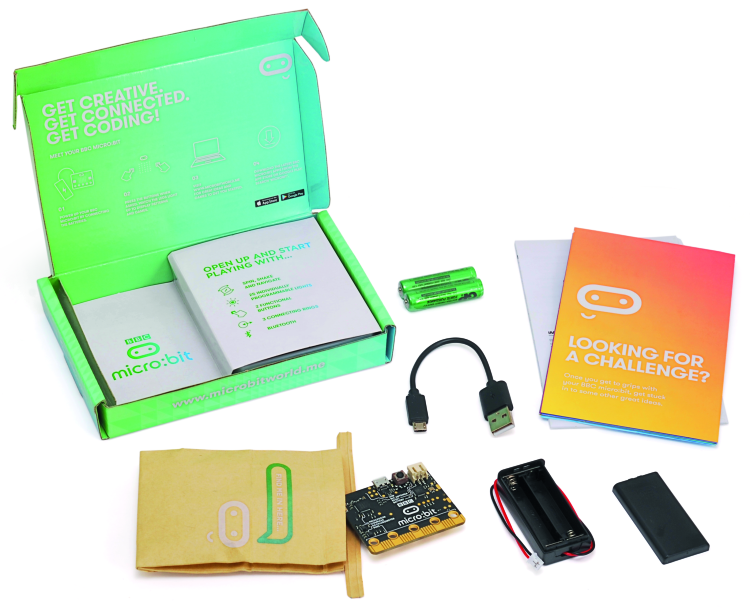
The “new” BBC micro:bit includes a 32-bit microcomputer in a 4 x 5 cm base, along with movement sensors, electronic compass, a Bluetooth module, a good number of I/O inputs, some buttons and many LEDs arranged in a matrix for developing graphical interfaces. In figure you can see what’s inside the micro:bit’s package we put our hands on, which includes the micro:bit, a USB cable, a battery holder and two AAA batteries. Besides, they offer a range of programming tools freely accessible over the web, allowing to program the micro:bit in a simple and intuitive way, respecting the most recent teaching paradigms for young students. Still along the lines of making things easier for those who take the first steps in the field of programming, they made available a web simulator that allows to write and try out your programs before downloading them on the micro:bit. It goes without saying that you can also save the programs created on your PC, and edit them at any time. Clearly, since the micro:bit is essentially a Arduino-like microcontroller, you can also load and execute just one program at a time.
The range of example programs are also available along with several tutorials, which are currently only available in English. So far, over 1 million units of BBC micro:bit have been distributed. The micro:bit is supported, besides BBC, the promoter and coordinator, by several other companies from different fields, with a common need to employ more and more technologies and therefore are looking for professionals who are able to carry out their projects. Among the companies involved in the project’s development we can name some of the major ones such as ARM, Barclays, element14, Freescale, Lancaster University, Microsoft, Nordic Semiconductor, Samsung, ScienceScope, Technology Will Save Us and The Wellcome Trust, besides much more supporting the union’s initiatives in various ways. In particular, in the widespread involvement activity of school institutions, of teachers and educators, providing them with the supporting learning resources such as interactive sessions, tutorials and projects. As it is becoming more and more common, the technical specifications of the device will be released following the open source formula.
Features
The micro:bit has the following functionalities and interfaces, highlighted in figure:
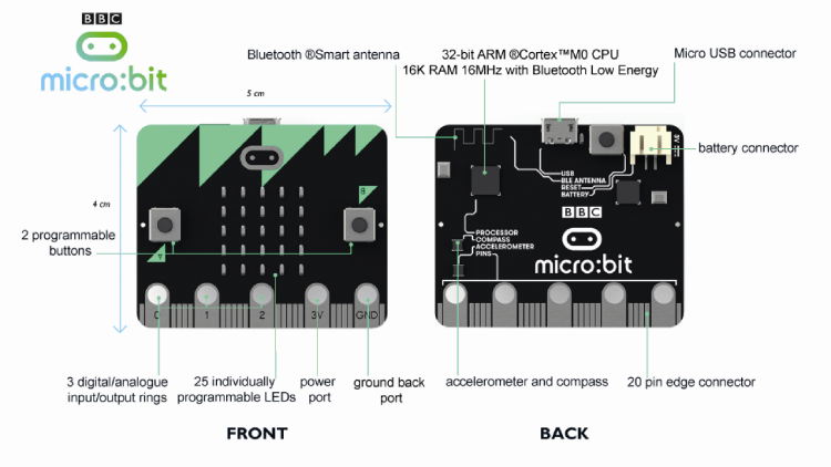
- 25 red LEDs that can be turned on with different intensities in order to create patterns, animations and games;
- Two keys that can be managed by software to customize its behavior;
- A reset and restart button;
- An accelerometer capable of detecting and recognizing several types of movement such as shaking, rotation and free fall;
- An electronic compass capable of detecting orientation and rotation in degrees in respect to the magnetic north. Another use might be as a (magnetic) metal detector;
- A USB connector to connect micro:bit to a PC and load software programs;
- a connector for external power;
- A Bluetooth Smart Technology module allowing to connect the micro:bit with other devices equipped with the same technology such as other micro:bits, PC, smartphone, Bluetooth keypads, tablets and cameras;
- A temperature sensor capable of detecting room temperature;
- A 24-pin connector, with five pins equipped with pads compatible with crocodile clips for connection. On the connector, there are both analog and digital I/Os available, a communication bus and other features that we are going to describe in detail below.
There are a series of shields which are specially designed to allow two enrich the range of applications that can be created using micro:bit.
Hardware description
The BBC micro:bit has been designed based on SoC nRF51, a microcontroller created for embedded applications, especially for smartphone accessories, wearable devices, security devices and wireless sensors. There is a consistent series of peripherals integrated into the chip. Moreover, there are several additional peripherals on the micro:bit. For transferring programs from the PC to the micro:bit, there is a USB interface created using a Freescale KL26Z chip.
NRF51 Application Processor
The programs transferred by the PC to micro:bit are executed on the RF51 chip on which the bootloader operating the transfer of the programs from the PC and their execution is installed by default. The transferred program encloses, in just one file, the code written by the user, the runtime code and the Bluetooth stack.
The GPIO pins available to the user refer to the same SoC. In particular, the SoC includes a 32-bit ARM Cortex M0 CPU with 16 MHz clock, 256KB ROM Flash and 16KB RAM.
Bluetooth communication
The micro:bit’s Bluetooth communication is taken care of, from a hardware perspective, by the 2.4 GHz transceiver (described below) and the software device Nordic S100 SoftDevice, providing a complete stack for low-energy Bluetooth communication, in order to allow the micro:bit to communicate with the widest array of devices, including smartphones and tablets. Bluetooth communication uses 2.4GHz ISM bands (Industrial, Scientific and Medical) 2.4GHz..2.41GHz on 40 (0 – 39) of the 50 2 MHz channels available. Data congestion is minimized thanks to Frequency Hopping.
Radiofrequency module
All the radiofrequency communication is managed by the 2.4 GHz hardware transceiver. The Bluetooth protocol is implemented by software. The transceiver includes by default the proprietary protocol Nordic Gazell, which allows exchanging information with other devices supporting the same protocol through small, very simple data packages. Most of the languages that can be used to program micro:bit are equipped with the “radio” interface which is implemented using the same Nordic-Gazell protocol. A “group code” automatically added by micro:bit’s runtime to data packages allows to manage a simple form of addressing and package filtering. Communication bandwidth is divided in 101 channels (0 – 100). Messages are transmitted unencrypted and can be 32 bytes or 255 bytes of length. Transmission power can be configured on eight levels from -30dbm (level 0) to +4dbm (level 7).
Buttons
On the front side of micro:bit there are two buttons. There is a single button in the bottom section. Front buttons are labeled A and B, as confirmed by the serigraphy on the printed circuit and can be used in the programs for any operation. Button debouncing is handled by the software runtime and the recognizable conditions are short pressure, long pressure and simultaneous pressure of both A and B buttons. The buttons operate following inverse logic, i.e. when the button is released, a pull-up resistance keeps the corresponding input to logic level “1”, while when the button is pressed, the contextual ground connection brings the corresponding input to logic level “0”. A and B buttons are connected respectively to P5 pin and P11 of the GPIO, which are also available on the comb connector that can be found on the printed circuit. The button on the back of the printed circuit basically works as a reset button and is connected both to the USB interface processor KL26 and the main nRF51 processor. Pressing the reset button reboots the application, both when micro:bit is powered by USB and when is battery-operated.
Display
The micro:bit’s display is composed of a red LED matrix organized in five rows and five columns. The runtime software of micro:bit refreshes the status of each LED with such a frequency that naked eye cannot perceive the flickering. For each LED included in the matrix there is the possibility to set brightness on a ten level scale. A peculiar feature is the use of the LED matrix in order to measure the intensity of ambient light. This can be done by the runtime software by periodically switching some pins of the LED matrix and measuring the voltage drop time, which is roughly proportional to the level of ambient light. Brightness measured is also returned on a value scale from 1 to 10ten
Sensors
On micro:bit’s printed circuit there are two integrated circuits that work as sensors, an accelerometer and a magnetometer. The accelerometer measures accelerations on three axes while the magnetometer can be used both as a compass and as a magnetic field detector. Both sensors are connected to the main controller via the 12C bus which refers to P19 (SCL) pin and P20 (SDA) pin of the GPIO connector. Two pull-up resistors are connected to said pins. The magnetometer can also generate an interrupt towards the main processor while the accelerometer can generate two different interrupts towards the main processor.
Accelerometer
The accelerometer can measure acceleration on three axes. The sensor can interpret data from the accelerometer to identify some specific behaviors directly through the hardware, such as freefall, or via software calculations such as sensor orientation (up or down) and shaking. The Freescale MMA8653FC IC composing the accelerometer communicates with the main processor over the I2C bus. Three ranges of measurement are available at 2, 4 or 6 G. reading resolution is 10 bits (0… 1023). The maximum sampling frequency is 800 Hz.
Magnetometer
The magnetometer is made using the Freescale MAG3110 integrated, capable of detecting the intensity of a magnetic field. Transformation in orientation data of the board, starting from the values detected, is carried out by dedicated algorithms included in the runtime software. The kinetic compass must be calibrated before the use. The calibration process is managed by the runtime software. The magnetometer communicates with the main processor using the I2C bus. Max sampling frequency is 80 Hz. Max magnetic field intensity measurable is 1000 µT (micro Tesla) with a sensitivity of 0.10 µT.
Temperature sensor
The main processor nRF51 includes a temperature sensor that can be accessed through the runtime software and provides an approximate in value of room temperature. The range of measurable temperatures goes from -25°C to 75°C, with a resolution of 0.25°C and an accuracy ± 4°C.
Comb connector
The comb connector is the main interface of micro:bit with the external world and provides a variety of digital, analytics, touch and PWM I/Os, besides the serial communication bus I2C and SPI. The comb connector terminals have a 1.27 mm pitch except for some pads which are larger than the others and have a central hole of 4 mm that can be used to connect a crocodile clip as you can see in figure. In particular, terminals P0, P1 and P2 have 10 MΩ pull-up resistors connected to them, which allow enabling the terminals as touch sensors. In this configuration, terminals are normally at logic level high. When you touch a terminal and ground at the same time, the interested terminal goes to logic level low (0 V). During normal use, i.e. in non-touch mode, a pulldown resistance is enabled via software on these terminals so that the terminals are capped at logic low when they are on standby and can be brought to logic level high when connected to the positive terminal. On the terminals from one side of the printed circuit are electrically connected to the corresponding terminals on the opposite side. In order to avoid short circuits or generate interferences, terminals on the left and right of the large pads GND and 3 V are also connected to ground (GND) and positive voltage (3 V) respectively. The terminals on the connector can be assigned with different functions and can be set by software according to the user’s needs.

On the comb connector there are many of the communication and I/O features provided by the main processor nRF51. Many of the functions assigned by default can be disabled via software in order to transform respective terminals in general use imports/outputs. One important note regarding the amount of current that can be absorbed by the comb connector. The I/O pins can be configured both in std-drive mode and in high-drive mode. In the std-drive mode, each pin can supply up to 0.5 mA of current while in high-drive mode, Max current supplied is 5 mA provided that the number of terminals in high drive-mode simultaneously is set at three. Finally, the resolution of ADC conversion is 10 bits (0..1023).
Powering the micro:bit
The micro:bit can be powered by three different sources; through the USB connector, using an external battery connected to the dedicated connector and by connecting a power source at the 3 V and GND terminals on the comb connector. In case of USB power, voltage is set to correct values for micro:bit by the processor’s internal regulator with KL26 interface. The circuit switching between power sources uses a low-Vf (max 0.23V) diode in order to prevent voltage reversals between different sources. You must pay attention if you decide to power the micro:bit using the 3 V and GND terminals of the comb connector. The 3 V terminal is directly connected to the integrated on the board and a voltage over 3.6 V may irreparably damage the micro:bit. The 3 V connector can be used to power small external circuits (Max current 90 mA).
USB communication
USB communication with micro:bit (version 1.1 @ 12Mbit) is handled by software with a dedicated coded stack in the firmware of the integrated with KL26 interface, which includes a 32-bit ARM Cortex M0 CPU with 16 MHz clock, 32KB Flash ROM A 4KBRAM. The software stack allows to see the micro:chip from a normal PC as an external memory drive, just like a USB stick. This feature allows to transfer the software from the PC to the micro:bit by simply dragging the file from the original folder to the root folder on the micro:bit. It is also possible to use USB connection as serial connection for transmitting and receiving data from external devices such as other micro:bit’s, microcontrollers and PCs.
BBC micro:bit runtime
Programming flexibility and simplicity of micro:bit is guaranteed by the presence of runtime software, a software architecture that can “interpret” and correctly execute programs written in various languages supported. The runtime is composed by different software layers that allow, overall, to simplify micro:bit programming using two different programming languages and development environments available for micro:bit such as Microsoft Block Editor, Code Kingdom’s JavaScript, TouchDevelop and PXT. Other development languages and programming environments exist before the creation of micro:bit and have been adapted to be used with it, such as ARM mbed and MicroPython. The runtime architecture is shown in figure. The lower layer is the hardware abstraction level (HAL) provided by the ARM mbed environment. ARM mbed provides a useful software layer for developers which can be used to write software that can be executed on the whole family of ARM Cortex processors, such as the Nordic nRF51822, used in micro:bit and it standardizes access and use of peripherals and hardware resources like the GPIO and the serial buses, SPI and I2C. Based on this layer, Lancaster University built the actual runtime, which provides a series of high-level interfaces for the users (the students), to interface micro:bit’s features with the various development language provided in an easy and standard way. Most of the “blocks” used in “educational” programming, such as those in Microsoft Blocks or PXT, recall functions provided by the runtime.

The main components of micro:bit’s runtime are:
- A scheduler allowing micro:bit to execute different tasks (almost) simultaneously;
- An event management system called “message bus” that allows to write event-based code. This system allows to communicate what is happening on the interfaces with the external physical words to the code written by the user; from one button being pressed to a message received over the radio;
- A series of device drivers that allow communicating with most of the hardware peripherals on the micro:bit including the LED display, the different sensors, the file system, the radio profiles and the Bluetooth;
- A series of datatypes allowing to make memory management for memorization of application data transparent. This feature, originally implemented to be used with high-level languages, is also very useful for who wants to try their hand at programming micro:bit in C and CC++.
One note for those who want to take a stab at programming micro:bit in C or C++. This can be done in two ways. You can directly use the HAL mbed (Hardware Abstraction Layer) to access low-level peripherals or, as highly recommended, use the runtime exposing a series of APIs that can be used with C and C++ programs. The API interface is modular and therefore only strictly needed modules can be included in C and C++ programs, for instance, only the module needed to manage the LCD display.
You can also find a lot of documentation regarding micro:bit’s runtime here:
https://lancaster-university.github.io/microbit-docs/
Programming
After this technical & philosophical overview, let’s talk about how to actually program micro:bit by presenting the different development environments available. The characteristic of most development environments is that they can be accessed over the web, without the need to install software on your PC.
After loading the applets of the development environments on the browser’s cache, you can write your own programs even without an Internet connection. For mobile devices, such as tablets and smartphones, besides the web environments above that are also free apps which can be freely downloaded from the App Stores.
I order to get started, we have to connect the micro:bit to our PC using the USB cable included in the package. Once connected, micro:bit should be immediately recognized. In case of windows XP you will be asked to install the driver.
Now connect to the reference website for micro:bit at the address:
http://microbit.org/
In the main page click on the “Let’s Code” button you will be shown the page visible and missing the different programming environments. Let’s take an in-depth look at them.

Microsoft PXT (Beta)
Microsoft PXT (Programming Experience Toolkit) is a programming environment created by Microsoft (still in Beta) which supports both a block visual environment akin to Scratch and Javascript. On the left side of the editor there is the collection of blocks divided by category. In order to compose the program, you have to choose the desired block from the collection contained in it, and drag it to the central space. Remarkable is the fact that one block represents the entire display. By clicking on the single “LEDs” you can change the status from on to off and vice versa as you can see in the example.

Note that the simulator in the top right corner can be activated using the button with the arrow or square icon, depending on the status. After composing a program, all you have to do is click on a white space in the editor’s panel in order to see the program running in the simulator. Other noteworthy features are those allowing radiofrequency communication between two or more micro:bits.

For each block you can open a help window by right-clicking on it. To create the files to transfer on the micro:bit click on the “download” button. You’ll be asked to save the files. Choose a folder and save. The method for transferring the program to the micro:bit is the same for all the development environments and we will describe it at the end of the article.
By clicking on the “Projects” button in the top left corner, you will see the pop-up window shown in figure which allows to save the “sources” in development on your PC and import them from the PC to the development environment.

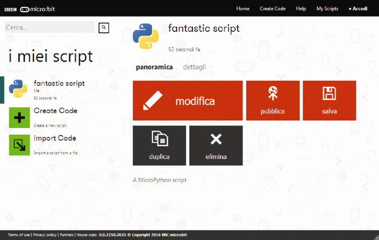
Python
Of course, there is also a development environment based on the Python version known as MicroPython. MicroPython was and currently is in development in order to allow programming of the microcontroller in a language compatible with Python. The method requires to write the program manager and then “inject” in the microcontroller where a dedicated virtual machine interprets it and execute it. In case of micro:bit, these operations are carried out by the runtime. The opportunity to use Python allows providing continuity, from a hypothetical educational perspective, towards the use of more complex systems such as microcomputers able to host GNU/Linux, like the Raspberry Pi series. In order to open Python environment, click on the “Start with this editor” button in the “Python” section. The editor for programming with Python will open up. In order to run a test, try to edit the text shown in figure.

Save the program to a file by clicking on the “Download” icon.
Comprehensive documentation including instructions available in Python for micro:bit can be found here:
https://microbit-micropython.readthedocs.io/en/latest/
By clicking on the “Snippets” button you can access a comprehensive library of samples and code fragments which can be reused in your projects. By clicking on the arrow symbol in the top left corner you will see the window shown in the figure which allows saving the “sources” in development on your PC and import previously saved programs from the PC to the development environment. You can also switch from one development environment to the other. In fact, this interface is shared by the development environments that we are going to describe below.
Microsoft Block Editor
Microsoft Block Editor is a visual editor very similar to Scratch and represents the starting point for those who want to start programming. Just like Scratch, it is very simple to use but it’s not a toy. It allows diving deep in structured programming and event management. Composition method of the program consists in choosing the blocks representing the instructions, drag them to the editor’s panel, configure their customizable parts and “fit them together” in the right way. You are helped in doing this by the blocks shape. The blocks connect only if they are compatible and shapes match. Clearly, this doesn’t guarantee that logics created is the one you wanted. For that, we must analyze what we want to create and translated in coherent algorithms. In this development environment we can also find very “expressive” blocks, such as the one available to configure the LED display, just like it happens with Microsoft PXT environment. This similarity between the visual and textual interfaces of the programming environments available allows for a gradual and incremental passage from visual interface languages to traditional languages with textual interface. In this development environment you can too execute the code you have just written in a simulator in order to run the tests, before transferring the code itself on the physical micro:bit. In order to activate the simulation environment you must click on the “Play” icon, the second in the top left corner. Once accessed the simulation environment, we can try out the different functionalities. In the example shown in the figure we tried to create a small event system that detects when buttons A and B are pressed, whether independently or simultaneously, besides shaking. Each condition is highlighted with a different configuration of the LED matrix.
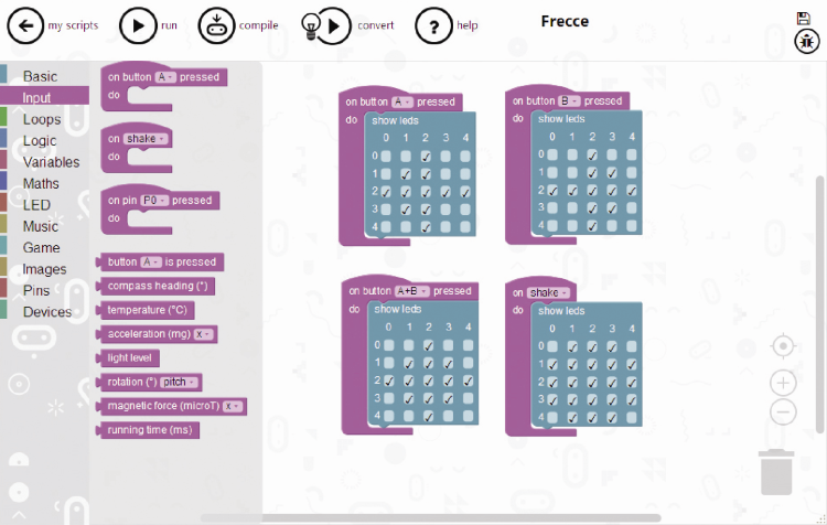
In the emulation environment shown in the figure the micro:bit image is shown with “functioning” buttons, a separate button for the simultaneous pressure of A and B and another button for simulating shaking. By moving the micro:bit with the mouse, acceleration values on three axes are highlighted. In the Block Editor development environment there are different “blocks” that allows detecting the status and values of the sensors. The icon with the micro:bit symbol allows to download the code on your PC and then transfer it to the micro:bit. The “Question mark” button opens the help section containing the description of each block and respective uses.

Microsoft Touch Develop
Microsoft Touch Develop environment was developed in order to create programs for micro:bit using tablets or other devices with touchscreens. Of course, it can also be used by normal PCs with mouse and keyboard. The language of Touch Develop is a scripting language with a highly structured syntax where the editor guides the layout of the structure blocks and the single lines of code. By clicking in the instruction area you can open a contextual box showing the different options available in the code section you are editing. By touching or clicking in sequence on the different blocks you can compose each code line and the instruction blocks. The example shown in figure was generated by converging the sample written with Microsoft Block Editor. In order to make the conversion, click on the button with the lightbulb in the little triangle pointing right. In the page that will appear click on the “Convert” button.

You will find yourself in the Touch Develop environment with the converted code on the left. In this case also, you can make use of the simulation environment, which can be activated by clicking on the triangular button pointing right (second button from the top on the left side). In order to download program to run on the micro:bit you have to click on the button with the symbol of the micro:bit. You can find the Undo button beside it. By clicking on the first button and top left corner, the one with the arrow pointing left, you can access the usual page where you can see the program source on the PC and import a previously saved program in the development environment.
Javascript
Finally, let’s mention the JavaScript development environment, which allows those with some programming experience to develop programs using the actual syntax of JavaScript, with a guided editor that supports the drag-and-drop method for composing code lines and code blocks, as we have tried to show.

By clicking on the “RUN” button you can activate the simulation environment seen in figure. In order to save the program on the PC and transfer it to the micro:bit click on the “COMPILE” button. If you want to save the source or import previously saved programs, go to “my scripts” and click on “MY SCRIPTS”.

Running programs on micro:bit
We have seen the technical features of micro:bit in various development environments that allow to program it and verify its functioning through the available simulators. Now, let’s take a look at how to transfer and execute our programs on the physical micro:bit. First, we must get ourselves a micro:bit and connect it to our PC through the USB cable. When it’s connected to for the first time, usually, micro:bit is recognized automatically. If this isn’t the case, and you see the driver configuration dialog, all you have to do is select the “search the Internet for a drive” option. Once connected and recognized, the micro:bit is seen as an external memory drive, basically just like a USB stick. Then, in order to load a program on the micro:bit, all you have to do is move it into a folder on your PC and from there, transfer it to the file system of micro:bit. When describing each development environment we have indicated how to obtain the “executable” file of our program and how to save it in a folder on our PC. Now you have to copy the file from that folder where you have saved it and paste it into micro:bit’s file system, or just drag it from the folder to the micro:bit. During file transfer, the LED on the back side of micro:bit will start blinking.
Once program has been transferred, it will run immediately as it usually happens with microcontrollers.
Now, the program will be permanently saved in the flash memory. If you turn the micro:bit off (cut the power) and then on again, or if you press the reset button, the last loaded program will be executed. This happens also when micro:bit is powered by a battery or through the 3 V and GND terminals of the comb connector. The micro:bit can be programmed with just one program at the time. It might happen to try and load a .hex program in the file system of micro:bit when another one is already present. In this case, transfer will not be successful. In order to solve the problem, all you have to do is power the micro:bit off and then on again. The previous file will disappear from the file system and you will have the chance to load the new one. In conclusion, we have to a great tool to learn how to code with different development environments and increasing difficulty levels that will allow us to learn and get an in-depth knowledge of the most diverse techniques for programming and use peripherals, sensors, wired or radiofrequency communication buses. A complete instrument in order to experiment with what is called coding, physical programming and IOT. What are you waiting for?
From openstore
