
In the previous episode, we have described the library and the functions made available by it. Now we will introduce a series of sketches through which you will see in practice how the library works and it’s potential. The sketches will implement functions such as receiving or sending SMS, voice calls, managing certain generic commands, as well as writing PIN codes, PUKs etc. in EEPROM.
The library is designed to do most of the work and leave the easier tasks to the developer, who will simply have to adapt the library to their own needs and applications. We remind you that the programming of PIN and PUK codes in EEPROM cannot be done directly by the Arduino IDE, but it can be done exclusively with a special sketch for writing data in EEPROM.
That said, we begin the description of the sketches by programming the codes in EEPROM.
EEPROM programming
The first operation to be carried out to use the GSM Shield is to program the Arduino EEPROM with the codes necessary for the correct functioning of the other sketches.
We test our hardware with some sketches in preparation for the field use of the supported GSM/GPRS modules. Third and final part.
The file “GenericCmd_GSM.h“, just at the beginning of the file, contains the list of data to be stored in EEPROM memory.
At present, these are a series of numeric codes identifying the following items:
- Generic password 1 → 8 numeric characters, occupied space 11 bytes (includes quotation marks and the closing character of the string);
- Password PH PUK → numeric characters, occupied space: 11 bytes;
- Password PUK2 → 8 numeric characters, occupied space: 11 bytes;
- Password SIM PUK → 8 numeric characters, occupied space: 11 bytes;
- Generic password 2 → 4 numeric characters, occupied space: 7 bytes;
- Password PH PIN → 4 numeric characters, occupied space: 7 bytes;
- Password PIN2 → 4 numeric characters, occupied space: 7 bytes;
- Password SIM PIN → 4 numeric characters, occupied space: 7 bytes.
To tell the compiler that you want to enter data in EEPROM you use the following syntax:
const uint8_t EEMEM LONG_GEN_PSWD[11] = “\”12345678″”;
In practice, we have defined a whole variable without a sign (uint8_t) of constant type (const) that through the directive “EEMEM” tells the compiler that the data are part of the EEPROM. Note that in the example shown you we are not storing a single variable, but an array of bytes of length 11 containing a numeric password.
The memory location from which to start writing the bytes defined above is decided by the compiler unless it is set differently from code and the starting address of each array is then retrieved via code so as to allow access to data in both reads and write.
The compiler then generates a file with the extension .epp that is stored in the directory:
C:\Documents and Settings\YourUserName\LocalSettings\Temp\arduino_build_xxxxxx
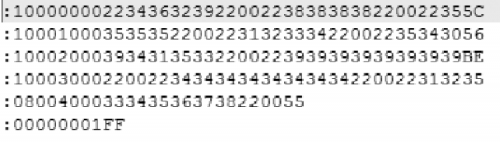
Fig. 1 shows the contents of the .epp file generated during compilation.
Now, to retrieve the starting addresses of the different arrays defined in EEPROM you must use the usual syntax in C:
&LONG_GEN_PSWD[0]
This value is then saved in a variable. In our case we have defined a data structure to retrieve the starting addresses of all the arrays used for passwords, which is:
struct
{
uint8_t StartAddPin1Code;
uint8_t StartAddPin2Code;
uint8_t StartAddPhPinCode;
uint8_t StartAddPuk1Code;
uint8_t StartAddPuk2Code;
uint8_t StartAddPhPukCode;
uint8_t StartAddShortPswdCode;
uint8_t StartAddLongPswdCode;
EepronAdd;
Consequently, the syntax to be used to exploit this data structure will be:
EepronAdd.StartAddLongPswdCode =&LONG_GEN_PSWD[0];
EepronAdd.StartAddPhPukCode =&PH_PUK_CODE[0];
EepronAdd.StartAddPuk2Code =&PUK2_CODE[0];
EepronAdd.StartAddPuk1Code =&PUK1_CODE[0];
EepronAdd.StartAddShortPswdCode=&SHORT_GEN_PSWD[0];
EepronAdd.StartAddPhPinCode =&PH_PIN_CODE[0];
EepronAdd.StartAddPin2Code =&PIN2_CODE[0];
EepronAdd.StartAddPin1Code =&PIN1_CODE[0];
Finally, to facilitate this operation the lines of code above exposed have been grouped in a library function to call up during the “Setup” section of the sketch, in particular, we have:
EepromStartAddSetup();
If this function call is omitted the compiler will not generate the .epp file, ignoring the data assignment code in EEPROM.
Now, as we all know, the Arduino IDE programs only the Flash of the microcontroller on the board used and totally ignores the programming of the EEPROM, even if the compiler has generated the file. epp. That said, there are two ways to program the EEPROM: the first is to use the command line tool “avrdude“; the second is to write a dedicated sketch and that’s what we decided to do to solve the problem.
Let’s take a look at the very simple sketch “GSM_SetEeprom” which has the only purpose of programming the EEPROM of the microcontroller. Once programmed we can download in the Flash of the Arduino boards our application sketches for the management of SMS, voice calls and more.
This sketch is valid for the Arduino Uno, Arduino Mega 2560 and the corresponding Fishino boards. Remember to select in the library the Arduino tab you want to use.
Let’s start with the setup section or “void Setup()“; the first thing to do is to call up the function to retrieve the starting addresses in EEPROM where the passwords are stored, then you have to call up the function:
EepromStartAddSetup();
The programming function of the EEPROM is then called up:
Initialize_PIN_PUK_Eeprom();
Finally, wait for a time of 500ms and then initialize the UART to which the serial monitor is connected in order to verify that the EEPROM has actually been programmed with the desired data. To initialize the debugging UART, the library function must be called up:
Gsm.EnableDisableDebugSerial(true, BAUD_115200);
This activates the UART and initializes it at a speed of 115200 Baud. Finally, we activate the library interrupts, i.e. the TIMER1 for the time base and the external interrupt INT0 or INT4, depending on whether the Arduino Uno or Arduino Mega is used (in this sketch the external interrupt is not used).
Isr.EnableLibInterrupt();
You wait for another 500ms and then you load a time variable with a time of 15 seconds. Every time this timeout expires, the system reads the stored data in EEPROM and sends it to the serial monitor so that the user can check that it is correct.
Isr.TimeOutWait = T_15SEC;
The setup section ends and the code goes to the main (void loop()) where there is only one function that has the purpose of reading the data in EEPROM:
Verify_Eeprom();
Now let’s quickly analyze the function “Initialize_PIN_PUK_Eeprom()” which has the sole purpose of writing data in EEPROM. Then let’s see the code section to write the code Pin1 (SIM PIN):
Add = Gsm.EepronAdd.StartAddPin1Code;
eeprom_write_byte((uint8_t *)Add++, 0x22);
eeprom_write_byte((uint8_t *)Add++, ‘4’);
eeprom_write_byte((uint8_t *)Add++, ‘6’);
eeprom_write_byte((uint8_t *)Add++, ‘2’);
eeprom_write_byte((uint8_t *)Add++, ‘9’);
eeprom_write_byte((uint8_t *)Add++, 0x22);
eeprom_write_byte((uint8_t *)Add, 0x00);
First of all, we need to load in the pointer variable “Add” the starting address in EEPROM from where to start writing the data. In this case, the starting address is the PIN1 code. Seven writes follow and each time you write, the pointer is increased by one point to the next memory location. The first and penultimate stored values are quotation marks. In fact, PIN codes, PUK codes etc. are usually always enclosed in quotation marks. The closing character 0x00 ends the string. This syntax is replicated for all codes to be saved in EEPROM.
Now let’s analyze the code verification function (Verify_Eeprom()) which, as mentioned before, prints on the serial monitor the data stored in EEPROM every 15 seconds. As before, we only analyze a portion of the code:
Add = Gsm.EepronAdd.StartAddPin1Code;
AddressBuffer, “0x%04X”, Add;
Serial.print(“Address: “);
Serial.print(AddressBuffer);
Serial.print(” -> PIN1 = “);
Serial.print(char(eeprom_read_byte((uint8_t *)Add++))));
Serial.print(char(eeprom_read_byte((uint8_t *)Add++))));
Serial.print(char(eeprom_read_byte((uint8_t *)Add++))));
Serial.print(char(eeprom_read_byte((uint8_t *)Add++))));
Serial.print(char(eeprom_read_byte((uint8_t *)Add++))));
Serial.print(char(eeprom_read_byte((uint8_t *)Add++))));
Serial.print (“\n”);
First, we retrieve the address of the PIN code 1, we print on the screen the string that identifies what we have read and his starting address and finally the content of the EEPROM.

Fig. 2 shows what is read from the memory, from PIN1 to the generic 4-digit password. This data is printed on the screen once every 15 seconds.
The last curiosity concerns the management of the time variable “Isr.TimeOutWait” used in this sketch to decide how often to print the data read. At the base of all this, there is the TIMER1 managed and configured by our library which generates a stable interrupt every 2 ms. This time is called the time base and identifies the resolution that our time variables used by the library may have (±2 ms).
Now for our sketch we need a time of 15 seconds so the value to load in the variable will be equal to 7,500, this value is decreased by one unit each time the interrupt is triggered. When the variable reaches zero, it means that 15 seconds have passed. At this point, the sketch prints on the screen and reloads the variable.
Sketch Send Generic Commands
Let’s now comment on the sketch “GSM_GenericCommand” which shows how to use a set of basic commands implemented in the library. This sketch is compatible with the Arduino Uno, Arduino Mega 2560 and Fishino boards of the same name. Remember to select in the library the Arduino tab you want to use.
The sketch is made up of a single file and at the top of it we find a series of declarations about the state machines realized for the management of the various tasks, one for the sending of commands and one for the printing on a serial monitor of the answers received by the GSM module about the AT commands sent to it. A series of strings follow, all stored in the microcontroller’s Flash memory, which are necessary during the printing of the answers on the monitor in order to make it clear what you are talking about.
Let’s start as usual the discussion from the Setup section (void setup()) in which we must initialize the library to perform its functions. As already done in the previous sketch we must first call up the function:
EepromStartAddSetup();
This initializes the data structure with the pointers in memory for the recovery of passwords saved in EEPROM, followed by four functions necessary to initialize and test the I/O of the Arduino board in use. We remind you that the shield hardware includes a series of LEDs connected to the I/Os of the Arduino boards, useful both for debugging the code (Trigger) and for highlighting significant events such as the reception of an SMS or other (the user has full freedom in managing these LEDs depending on the application he is creating). The library provides the appropriate functions for their proper use). So, we have:
I.SetOutputTrigger();
I.SetOutputLed();
I.CheckOutputTrigger();
I.CheckOutputLed();
The first function is used to initialize the trigger I/Os and the second function initializes the I/Os with the diagnostic LEDs (Arduino Mega 2560 only). The last two functions are used to test the newly configured I/O, turning on and off the various LEDs in sequence to check if they work at the start-up.
The next step is to enable the serial debug to print on the monitor the answers received from the GSM module; note that the code to print on the monitor is not part of the library, but in this sketch we wrote a special function to perform this task (remember the strings saved in the Flash explained earlier).
The serial port is configured at a speed of 115200 Baud:
Gsm.EnableDisableDebugSerial(true, BAUD_115200);
The other possible speeds are: BAUD_2400, BAUD_4800, BAUD_9600, BAUD_19200, BAUD_38400, BAUD_57600.
You can also set it if you want: BAUD_230400, BAUD_250000, BAUD_500000, BAUD_1000000.
Those listed are all constants defined in the library, to be passed as an argument to the function. In the next step, we enable interrupts:
Isr.EnableLibInterrupt();
and set communication serial 1 (UART 1) to the GSM module:
Gsm.SetBaudRateUart1(true, BAUD_19200);
The latter can be hardware or software, depending on the configuration made in the file “IO_GSM.h” and the setting given to the jumpers on the shield. If you are using a software serial, we recommend that you do not exceed a speed of 38,400 Baud, preferably 19,200 Baud. If you are using hardware serial, you can safely set speeds of up to 115,200 Baud. Then the buffers used for serial communication are cleaned and then the initialization of the GSM module is started, sending in sequence the command to switch on the module and the initialization of the machine in states for the management of the UART:
InitPowerON_GSM();
Gsm.UartFlag.Bit.EnableUartSM = 0;
Gsm.ExecuteUartState();
Gsm.UartFlag.Bit.EnableUartSM = 1;
With the code lines just described, the setup section of the sketch ends. Once the latter has been executed, the code passes to the main, i.e. the usual “void loop()“, in which we find the management code of the state machines for the initialization of the GSM module and the sending of the AT commands at full speed. The following code can be applied in all applications where you use our library and is the starting point. So, we have:
Gsm.ExecuteUartState();
if (Gsm.GsmFlag.Bit.GsmInitInProgress == 1) {
InitGsmSendCmd();
InitGsmWaitAnswer();
else {
Gsm.UartContinuouslyRead();
ProcessUnsolicitedCode();
Gsm.GsmAnswerStateProcess();
#ifdef ARDUINO_UNO_REV3
I.LedBlink(TRIGGER_2, 25, T_2SEC);
#endif
#ifdef ARDUINO_MEGA2560_REV3
Io.LedBlink(PIN_LED9, 25, T_2SEC);
#endif
}
The first line recalls the function that manages the machine in states of sending and receiving data via the serial port (hardware/software). The serial communication management requires three states:
– IDLE, where the system waits to send an AT command to the GSM module;
– SEND, required to send the AT command to the module;
– WAIT, where you are waiting for a response from the GSM module, this function is used both during the initialization of the module and during the sending of commands AT in full.
Immediately there is the conditional code with which the system checks if the initialization of the GSM module is in progress (Flag Gsm.GsmFlag.Bit.GsmInitInProgress to “1” logical) or the sending of generic AT commands (Flag Gsm.GsmFlag.Bit.GsmInitInProgress to “0” logical).
When the above flag is at level “1”, the two functions for the management of the machine are called to send the AT commands necessary to set the GSM module; the same machine aligns the speed of the UART set by the user with that of the GSM if the two are different.
During initialization, the system also checks whether the PIN code should be sent to the SIM card if it is enabled. The code is stored in the EEPROM memory, as explained in the previous sketch and the pointer to it was recovered with the first line of initialization code.
In the second part of the conditional code, there is the indispensable function for the decoding of the answers received by the module (Gsm.GsmAnswerStateProcess()). This is flanked by two other functions that deal with intercepting any data sent independently by the GSM module which may contain useful information such as “Unsolicited Code” (Gsm.UartContinuouslyRead() and Gsm.ProcessUnsolicitedCode()). The following are currently managed: CRING, Phonic Call and CREG.
Finally, we have also included the management of one of the diagnostic LEDs used to highlight that the system has left the initialization condition and is now fully operational. Depending on the Arduino board you choose, LED 9 (Arduino Mega) or Trigger 2 (Arduino Uno) will be used.
During initialization, the LED connected to trigger 3 flashes to highlight this condition. The conditional block described above is essential for the correct use of our supported GSM modules management library.
Outside the conditional code there are all the functions necessary for the implementation of the application in question and released from our library: for example, the one to send commands AT base in perpetual sequence (Send_AT_Cmd()) and the printing on the monitor of the responses received from the GSM module (PrintDataReceived()).
Each time a command is sent, the system records the response obtained and makes it available to the user. In particular, we have the verification of GSM module registration to the cell by its operator (AT+CREG?), verification of GSM signal strength (AT+CSQ), GSM module status (AT+CPAS), operator verification (AT+COPS?), manufacturer identification (AT+GMI), model identification (AT+GMM), software revision loaded (AT+GMR), product serial number (AT+GSN) and finally reading the date and time from the real time clock on the GSM module (AT+CLCK?). Below is what is printed on the serial monitor following the response received to the AT commands sent, i.e. the responses received and totally decoded.
============ CPIN ============
SIM OK
============ CREG ============
Registered, home network
Location area: “0065”
Cell ID: “16F3”
============ CSQ ============
Rssi: 11
Ber: 0
============ CPAS ============
Ready (MT allows commands from TA/TE)
============ COPS ============
Automatic mode; <oper> field is ignored
Long format alphanumeric <oper>; up to 16 characters
Operator name: “TELECOM ITALIA
============ GMI ============
Manufacturer Identification: SIMCOM_Ltd
============ GMM ============
TA Model Identification: SIMCOM_SIM800C
============ GMR ============
TA Revision Identification of Software Release: Revision:1418B04SIM800C32_BT
============ GSN ============
TA Serial Number Identification (IMEI): 866104027073389
============ CCLK ============
Date: 01/01/04
Time: 00:10:40
GMT: 0
==============================
This makes the answers more readable. All strings printed on the serial monitor are stored in the microcontroller’s Flash and do not take up space in the SRAM.
The above AT commands are sent at a distance of 1 second from each other and to manage the sending sequence we have a machine which has been built with the usual construct “switch” (function “void Send_AT_Cmd(void)”). The function that prints the extrapolated information on the monitor also works using a state machine with the same construct (“void PrintDataReceived(void)” function).
Sketch management SMS and voice call
In Listing 1 you will find the sketch “GSM_SmsOnly” able to manage SMS. It is a very simple sketch and dedicated to this specific function. The sketch “GSM_Sms_PhonicCall” (which you will find among the many examples of the library) allows us to try some basic functions regarding the sending / receiving of SMS and the ability to make a voice call to a fixed mobile phone number, stored in the Flash, or to call any phone number through a special command string sent by serial monitor.
This sketch is compatible with Arduino Mega 2560 and Fishino Mega boards. Remember to select the Arduino tab you want to use in the library.
This sketch consists of four rows:
- “GSM_Sms_PhonicCall“, a file containing all the declarations of variables and constants used in the sketch as well as the basic functions used to manage the application;
- “DigitalInput“, a file containing the functions for managing the P3 and P4 buttons of the shield (debouncing of buttons and code for activation of SMS sending functions or activation of a voice call to a fixed network number stored in Flash);
- “DigitalOutput“, a file containing the I/O management functions configured as outputs (Trigger and LED);
- “TimerInt“, a file containing the Timer5 configuration and management code used as a time base for this sketch.
Listing 1
#INCLUDE <AVR/EEPROM.H>
#INCLUDE “UART_GSM.H”
#INCLUDE “IO_GSM.H”
#INCLUDE “ISR_GSM.H”
#INCLUDE “GENERICCMD_GSM.H”
#INCLUDE “SECURITYCMD_GSM.H”
#INCLUDE “PHONEBOOKCMD_GSM.H”
#INCLUDE “SMSCMD_GSM.H”
#INCLUDE “PHONICCALLCMD_GSM.H”
#INCLUDE “GPRSCMD_GSM.H”
SECURITYCMD_GSM SECURITY;
PHONEBOOKCMD_GSM PHONEBOOK;
SMSCMD_GSM SMS;
PHONICCALLCMD_GSM PHONICCALL;
ISR_GSM ISR;
IO_GSM IO;
GPRSCMD_GSM GPRS;
CONST CHAR SMS_PHONE_NUMBER[] PROGMEM = “\”+3934900\””;
CONST CHAR SMS_TEXT[] PROGMEM = “HELLO WORLD”;
#DEFINE TRUE 0
#DEFINE FALSE 1
TYPEDEF VOID STATE;
TYPEDEF STATE (*PSTATE)();
// STATES MACHINE USED TO MANAGE THE INPUTS (P3 AND P4)
PSTATE INPUT_MANAGEMENT;
BOOLEAN SENDSMS;
UINT8_T DEBOUNCINGTIMEOUT; //DEBOUNCING TIMEOUT
UINT16_T TIMEOUTP3; //TIMEOUT TO MANAGE P3
UINT8_T P3_BUTTON = 9; //INPUT BUTTON P3
UINT8_T P4_BUTTON = 10; //INPUT BUTTON P4
UNION DIGINPUTSTATUS {
UINT8_T INPUT;
STRUCT {
UINT8_T P3_BUTTON : 1; // BIT 0
UINT8_T P4_BUTTON : 1; // BIT 1
UINT8_T FREE : 6;
} IN;
} DIGINPUTSTATUS;
UNION DIGINPUTREADED {
UINT8_T INPUT;
STRUCT {
UINT8_T P3_BUTTON : 1; // BIT 0
UINT8_T P4_BUTTON : 1; // BIT 1
UINT8_T FREE : 6;
} IN;
} DIGINPUTREADED;
UINT8_T DIGINPUTVAR;
VOID SETUP() {
//MANAGE THE DIGITAL INPUTS (P3 AND P4)
INPUT_MANAGEMENT = INPUT_IDLE;
GSM.PSWDEEPROMSTARTADDSETUP();
SETUPTIMER5(); //INITIALIZE TIMER 5
SETINPUTPIN();
IO.SETOUTPUTLED(); //SETS I/O LEDS
IO.SETOUTPUTTRIGGER(); //SETS I/O TRIGGERS
IO.CHECKOUTPUTLED(); //CHECKS I/O OUTPUT (LEDS)
IO.CHECKOUTPUTTRIGGER(); //CHECKS I/O OUTPUT
GSM.ENABLEDISABLEDEBUGSERIAL(TRUE, BAUD_115200);
ISR.ENABLELIBINTERRUPT(); //ENABLES INTERRUPT
GSM.SETBAUDRATEUART1(TRUE, BAUD_19200);
GSM.CLEARBUFFER(); //CLEAR LIBRARY UART BUFFER
GSM.INITPOWERON_GSM(); //START GSM INITIALIZATION
GSM.UARTFLAG.BIT.ENABLEUARTSM = 0;
GSM.EXECUTEUARTSTATE();
GSM.UARTFLAG.BIT.ENABLEUARTSM = 1;
DELAY(500);
ISR.TIMEOUTWAIT = T_15SEC;
SENDSMS = TRUE;
}
VOID LOOP() {
GSM.EXECUTEUARTSTATE();
IF (GSM.GSMFLAG.BIT.GSMINITINPROGRESS == 1) {
GSM.INITGSMSENDCMD();
GSM.INITGSMWAITANSWER();
} ELSE {
GSM.UARTCONTINUOUSLYREAD();
GSM.PROCESSUNSOLICITEDCODE();
GSM.GSMANSWERSTATEPROCESS();
IF (SENDSMS == TRUE) {
SENDSMS = FALSE;
GSM.READSTRINGFLASH((UINT8_T *)SMS_PHONE_NUMBER,
(UINT8_T *)PHONEBOOK.PHONENUMBER,
STRLEN(SMS_PHONE_NUMBER));
GSM.READSTRINGFLASH((UINT8_T *)SMS_TEXT,
(UINT8_T *)SMS.SMSTEXT, STRLEN(SMS_TEXT));
SMS.SETCMD_AT_CMGS();
}
IO.LEDBLINK(PIN_LED9, 25, T_1SEC);
}
DEBOUNCINGINPUT(); //DEBOUNCING (P3 AND P4)
INPUT_MANAGEMENT(); //MANAGE DIGITAL INPUT
}
Let’s start with the “GSM_Sms_PhonicCall” file, where the configuration of the variables and constants used in the sketch is at the top of the file. All strings used are stored in Flash.
In the Setup section (void setup()) we find the initialization functions already discussed in the previous sketch with the addition of the initialization of Timer 5 used as a time base:
SetupTimer5();
followed by the two input initialization functions for the P3 and P4 buttons and the I/O initialization configured as outputs, i.e. the trigger and diagnostic LEDs:
SetInputPin();
SetOutputPin();
The remaining initialization lines are identical to the previous sketch, also the serial debug, as well as the communication to the GSM module one are configured in the same way: 115,200 Baud for the former and 19,200 Baud for the latter.
We proceed by analyzing the main function (void loop()) in which we find a series of functions that are called in sequence infinitely.
The first two functions manage the buttons P3 and P4:
DebouncingInput();
Input_Management();
The first one intercepts the pressure of keys P3 and P4, to which it applies a debouncing of 50 ms. In this sketch, the debouncing time is set to 50 ms but you can increase or decrease it as needed. It’s all about loading the desired time constant into the time variable “DebouncingTimeOut“.

The second serves to manage the machine in states concerning the functions related to P3 and P4. If the P3 button is pressed for more than 3 seconds, an SMS is sent to a phone number stored in Flash; if P4 is pressed for the same time, a voice call to a phone number stored in Flash is initiated. These functions are described below:
ProcessStateMachineGsm();
Here you can find the management code of the serial communication to the GSM module with the usual conditional code that discriminates if you are performing initialization of the GSM module or an AT command transmission at full speed.
This code is identical to the one used in the previous sketch except for the management of the LEDs which obviously depends on the application. At this point follow all the functions concerning the application in place, in particular, we have:
ProcessSerialCmd();
ProcessUserAtCmd();
ProcessGenericAtCmd();
The first one is used to interpret the string commands sent from the serial monitor. In fact, through the serial monitor, it is possible to tell the application to whom to send a generic SMS, also specifying its content, and decide to which number to forward a generic voice call.
But let’s see how to do it better: suppose you want to send an SMS containing the text string “How are you? “to the telephone number “+393490000000“; the string command to be used will be the following:
CmdSms: “+393490000000″#How are you?
The string “CmdSms:” identifies that you want to send an SMS, follows the phone number that must always include the quotes and finally the text string you want to send.
The “#” separator must always be present between the phone number and the text string. If the command string is correct the system prints on the screen the following string “# Command received by user → CmdSms: ………..” where instead of the dots there is the phone number and the string of the SMS you are sending. Immediately after receiving the command, the system will start sending the SMS using the command AT+CMGS. If the serial light is active, you will see the AT command passing over the serial port with the relative answer.
If you want to make a voice call to a telephone number of your choice, the command to be sent will be:
CmdCall: +393490000000
In this case, in addition to the different command string, you have that the only parameter to pass is the phone number that, unlike before, should not be enclosed in quotes. Also in this case, the system will answer with a string of text to indicate that the command has been received and immediately after will start the voice call via the ATD command.
In both cases, sending SMS or voice calls, the phone number is saved in a library variable called “PhoneBook.PhoneNumber“. As for the SMS, its text is loaded into the library variable “Sms.SmsText”. Both are arrays of appropriate length.
Finally, there is a command string to delete all received SMS, in this case, the syntax of the command will be:
CmdEraseSms:
Without any additional parameters. Once the command has been received, the system will start a loop to delete the SMS from the SIM memory cells from cell 1 to cell 30. The delete command is AT+CMGD to which the number of the cell to be deleted must be passed. If you send an incorrect command string, the system will return the error string:
# Command syntax error. Retry
This is the last command string that can be sent from the serial monitor. If necessary, it is possible to add new command strings by adding the relevant code.
Now let’s analyze the function “ProcessUserAtCmd()” which contains the code for sending the AT commands used in the application. The code, through a construct “switch“, discriminates if it has to send an SMS or make a voice call and this action is selected by the buttons P3 and P4. Then pressing the P3 button for more than 3 seconds activates the SMS sending action (the SMS will contain the text string: “FuturaGroup GSM Library R.1.0.” which is stored in Flash. The phone number to which the SMS will be sent is also stored in Flash. Looking at the code is the number including the quotes). Pressing the P4 button for more than 3 seconds will activate the voice call to a phone number always stored in Flash (this time without quotes). To end an ongoing voice call, press the P4 button again, with just one touch, without prolonged pressure.
Finally, the function “ProcessGenericAtCmd()” which, like the previous sketch, provides a series of AT commands to be sent in a continuous cycle to the GSM module. In this sketch we have the following commands: GSM module status (AT+CPAS), GSM signal strength check (AT+CSQ), GSM module registration check to the cell by your operator (AT+CREG?), pin code check necessity (AT+CPIN?), operator verification (AT+COPS?), reading of the received SMS (AT+CMGR) only in case of interception of a “Unsolicited Code“, cancellation of the received SMS (AT+CMGD) and if requested by command string cancellation of all received SMS (AT+CMGD).
As the last function remained ProcessSmsReceived();
This, given a received SMS, has the task of processing it and if it contains valid command strings, it executes preset commands. The text of the received SMS can be found in the library variable “Sms.SmsText”. In case of sketch, the commands can act only on LED 7, present on the GSM shield, and perform the following: turn on LED 7, turn off LED 7 or make LED 7 flash for 3 seconds.
Then sending an SMS with the wording “Led7On” the LED 7 will light up, vice versa if you send the command string “Led7Off” the LED 7 will turn off. Instead, the string “Led7Blink” will flash the LED 7 for 3 seconds. The flashing will have a period of 250 milliseconds with a 50% duty-cycle. Command strings must be sent individually in upper and lower case as the code is case sensitive.
To conclude this explanation, below we report the string constants saved in the Flash memory that identify respectively the phone number you want to use to send the SMS, the text to use and finally the phone number you want to use for voice calling (P3 button for sending SMS and P4 button for voice calling as described above).
//====================================================
const char SMS_PHONE_NUMBER[] PROGMEM = “\”+3934900 _””;
const char SMS_TEXT[] PROGMEM = “FuturaGroup GSM Library R.1.0.”;
const char CALL_PHONE_NUMBER[] PROGMEM = “+3934900”;
//====================================================
As you can see, the telephone number for sending the SMS must always be enclosed in quotes, while the telephone number for the voice call must not. The text to be combined with the SMS must have a maximum length of 160 characters.
Security commands and phone book Sketch management
The “GSM_Security_PhoneBook” sketch allows us to test a series of commands related to the security and management of the phone book. In addition, we have maintained the ability to handle an outgoing voice call. Also, in this case, the sketch is composed of several distinct files, as done in the previous one, of which we have already given a brief description.
In this case, the only difference is in the file “GSM_Security_PhoneBook” which must handle different AT commands than the previous sketch. The file “GSM_Security_PhoneBook“, like the previous one, has in its head a series of declarations of variables and constants. The constants can be of string type (saved in FLASH, they identify the text to be displayed on the serial monitor or the string commands to be always sent from the serial monitor), or of numerical constants (they identify the ‘state machines’ states used in the sketch). In addition, the global variables used in this sketch are also defined.
The Setup section (void setup()) finds a series of initialization functions necessary to configure the library, as you can see the same functions already used in the previous one. Also in this case, the serial monitor is set to a speed of 115,200 Baud and the communication serial to the GSM module at 19,200 Baud.
Let’s now analyze the main function (void loop()) in which we find a series of functions that are called in sequence infinitely. As in the previous one, we have two functions to manage the debouncing of the two buttons P3 and P4 where in this case we only use the button P4 to trigger the voice call to a phone number saved in Flash memory:
DebouncingInput();
Input_Management();
The functions described above are followed by this one:
ProcessStateMachineGsm();
where you will find the serial communication management code to the GSM module with the usual conditional code that discriminates if you are performing a GSM module initialization or an AT command transmission when fully operational. This code is identical to the previous sketch except for the LED management, which depends on the application.
The functions follow:
ProcessSerialCmd();
ProcessUserAtCmd();
ProcessGenericAtCmd();
The first one is used to interpret the string commands sent from the serial monitor, that are different from the previous sketch (later we give a detailed description). The “ProcessUserAtCmd()” function, through the usual “switch” construct, is used to discriminate which AT commands should be sent to the GSM module. Among these, we have the voice call to a landline phone number (press P4 button) or to a phone number of your choice via serial command. In addition, there are all the other AT commands managed by the sketch and retrievable only through a command string sent from the serial monitor.
Finally, we have the function “ProcessGenericAtCmd()” which, like the previous sketch, provides a series of AT commands to be sent in a continuous cycle to the GSM module. In this sketch, we have the following: GSM module status (AT+CPAS), GSM signal strength verification (AT+CSQ), verification of GSM module recording to the cell by your operator (AT+CREG?), pin code need verification (AT+CPIN?), operator verification (AT+COPS?).
Let’s see how the command strings that can be sent from the serial monitor; we have already met the first available string in the previous sketch or the ability to forward a voice call to any phone number. The command string is the same, so please read again the description of the previous sketch.
As for the new command strings, we start from the management of the AT+CLCK command to lock/unlock some services provided by the GSM module.
The available command strings are:
CmdFacLock: <fac code>
CmdFacUnLock: <fac code>
CmdFacCheck: <fac code>
The first one is used to lock a service, to work the string command requires a code that identifies the service on which you want to act. Table 1 shows the correspondence between the code and the service. The code sent will then be passed as an argument to the library function for sending the AT+CLCK command. The AT+CLCK command also includes a password to block the service, this password is read from the EEPROM memory, remember what was said with the first sketch analyzed?
Table1

If you want to unblock a service, use the second command string with the corresponding code. Also in this case, the password will be read from the EEPROM memory.
Finally, we have a command string to query the GSM module and see if the service is blocked or not. In this case no password is needed, the GSM module will return “0″ if the service is not blocked and “1” if the service is blocked. This information is easily available from the data structure “Security.SecurityFlag” and more in detail from the flag “Security.SecurityFlag.Bit.ClckStatus”.
Below you see the sending of the AT command to perform the unlocking of the service related to the PIN code of the SIM.
AT+CLCK=”SC”,0,”4629″
OK
Instead of the code that activates the SIM lock via PIN code, we report below.
AT+CLCK=”SC”,1,”4629″
OK
Finally, below you see the code that performs a test on the status of the service related to the SIM.
AT+CLCK=”SC”,2
+CLCK: 1
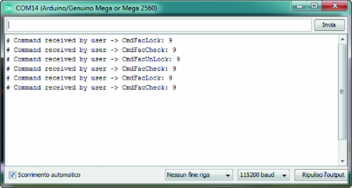
Fig. 3 shows the serial monitor with the command strings sent, pay attention to the syntax of the commands which are all case sensitive. Otherwise, the system will return an error string. Another command string implemented concerns the possibility of changing the password to services via the AT+CPWD command. So, we have the following string sent:
CmdFacSetPwd: <fac code>, <new password>
This command string requires two parameters: the first is the service code (see Table 1) while the second is the new numeric password which must be enclosed in quotes. Below, the command sent to change the password, which in this case corresponds to the SIM PIN.
AT+CPWD=”SC”,”4629″,”1234″
OK
The AT command expects to send both the current PIN code and the new PIN. The current PIN code is read from the EEPROM memory. If the AT command is successful, the old PIN code stored in EEPROM is replaced by the new one; in Fig. 4 you will find the relative command string sent from the serial monitor.
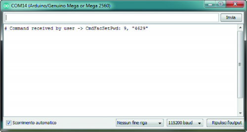
Fig. 4
Finally, we analyze the command strings to manage the address book, in this case we have:
CmdSelPhonebookMem: <MEM code>
CmdQueryPhonebookMem:
CmdReadPhonebookMem: <MEM add>
CmdWritePhonebookMem: <MEM add>, <PhoneNumber>, <PhoneNumberType>, <Text>
CmdErasePhonebookMem: <MEM add>
The first command string is used to select the address book to work on; also, in this case, we have a code that identifies the address book (Table 2).
In our examples, we will work with the code 6 (SM) that identifies the SIM address book, selectable by sending the command AT+CPBS.
Table2
![]()
The second string is used to check how many memory locations of the selected directory are available and how many are already occupied; the following portion of the code shows that the SIM card directory has 250 memory locations and 5 of them are not free.
AT+CPBS?
+CPBS:”SM”,5,250
OK
The third string is used to read the desired memory location and requires, as a parameter, the desired index; the AT+CPBR command returns the phone number stored at the given address, the type of number and a brief description in string format.
The following portion of the code shows the data returned from reading location three of the address book.
AT+CPBR=3
“+CPBR:3,”+393xxxxxxx”,145,”Borisxxxxxxx”
OK
The fourth string is used to save a new phone number in the address book, the command requires four distinct parameters: address in the address book in which to save the new number, the phone number enclosed in quotes, the type of number and finally a descriptive text, also enclosed in quotes.

Fig. 5 shows the above, the AT+CPBW command saves in the memory location you are a new phone number.
AT+CPBW=6,”+3934xxxxxx”,129,”Angxxxxx”
OK
If you select an already occupied location it will be overwritten. The last command string is used to delete a memory location in the phonebook to remove a phone number.
Below you will find the AT+CPBW command with only the index parameter that performs the cancellation of the location.
AT+CPBW=6<CR><LF>
<CR><LF>
OK<CR><LF>
Conclusion
With this last sketch, we have concluded this examples overview. We want to give some more advice on the library use and in particular on the file “Io_GSM.h” in which you will find all the definitions necessary to configure the operation of the library based on the GSM module you want to use and according to the hardware available. So always remember to:
- select one of the supported GSM modules;
- select which Arduino board you want to use from the supported ones;
- select the hardware revision, which must match the hardware revision printed on the PCB;
- select between hardware or software UART1 (the choice depends on the configuration of the jumpers, for which we refer to the table in the file);
- enable the GSM module responses management sections, remembering that there are different sections available depending on the AT commands categories; in this case, you can enable multiple sections simultaneously, so we have:
- enable response management section for generic AT commands (ENABLE_ANSWER_GENERIC_AT_CMD_STATE);
-
enable command response management section AT related to security (ENABLE_ANSWER_SECURITY_AT_CMD_STATE);
-
enable management section responses to AT commands relating to the address book (ENABLE_ANSWER_PHONEBOOK_AT_CMD_STATE);
-
enable management section responses to AT commands related to SMS (ENABLE_ANSWER_SMS_AT_CMD_STATE);
-
enable management section responses to AT commands related to voice calls (ENABLE_ANSWER_PHONIC_CALL_AT_CMD_STATE).
If you fail to enable a section related to the AT commands sent, the system will not be able to handle the responses and will be waiting. If necessary, enable/disable debug sections.
Remember that there is a global definition that disables all debug code in the library and sub-definitions to activate targeted debug code.
From openstore
GSM compact interface with M95
Small Breakout for SIM928 GSM&GPS Module
