
Let’s discover a useful library to manage various low-cost GSM/GPRS modules, in order to provide cellular connectivity to our Arduino projects. Second part.
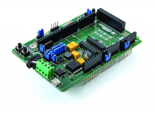
In the previous episode, we introduced the shield hardware and exposed the technical features and possible applications, as well as mentioned the library for Arduino, here we complete the previous speech explaining in detail its operation, which supports the boards Arduino Uno, Arduino Mega 2560, Fishino Uno and Fishino Mega 2560. The library is composed of the main file plus the secondary files containing the code necessary to manage a series of functions that send AT commands to the GSM module installed in the shield. The main file is GenericCmd_GSM.cpp and contains the infrastructure code that keeps the functions in the other library files interconnected. With a series of directives, it is possible to activate/deactivate parts of the code as well as select the desired Arduino board and the corresponding GSM module to be associated.
The modules currently supported by the library are:
– SIM800C (SIMCOM);
– SIM900 (SIMCOM);
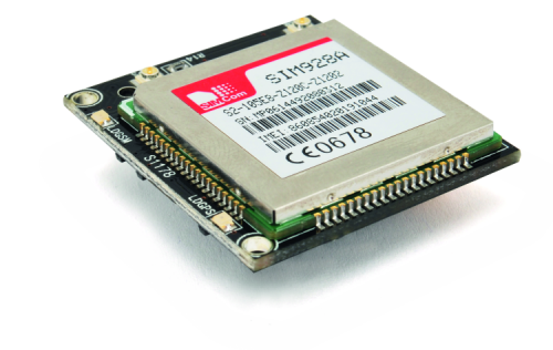
– SIM928A (SIMCOM);
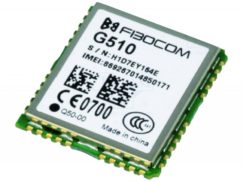
– G510 (FIBOCOM);
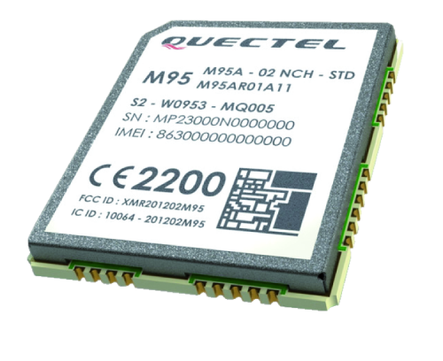
– M95 (QUECTEL).
We want to remind you that the SIM928A provides for the management of two serial numbers. For all the modules only the SMS and voice call management functions are currently supported, while the GPRS management functions for Internet connection and data sending/receiving are under development. In the future, the management part of the GPS system will also be developed.
To better understand some of the terms used below, you should remember that GSM modules can be defined as:
• ME (Mobile Equipment);
• MS (Mobile Station);
• MT (Mobile Termination);
• TA (Terminal Adapter);
• DCE (Data Communication Equipment).
The devices that control the GSM modules, by sending appropriate AT commands, can be:
• TE (Terminal Equipment);
• DTE (Data Terminal Equipment), a term equivalent to the application that runs on an embedded system and is responsible for the GSM module management.
THE GSM LIBRARY IN DETAIL
The library is designed for sending an AT command through a special function and waiting for the response from the GSM module. This is made possible by a series of state machines that take charge of both the sending of the AT command and the management of the response by the module. Currently, some common AT commands have been selected and implemented in the library.
To use it you must copy all the files that can be downloaded from the site github.com/open-electronics/GSM_Library_Arduino in the folder “C:\Program Files (x86)\Arduino\libraries/GSM2”. Once all files have been copied, the library must be initialized by the user depending on the hardware used and the GSM module selected. Special functions have also been developed to activate the process of GSM module initialization (module power on, and sending AT configuration commands) which is fully automated, including the request for the PIN code (if required) and sending it to the GSM module. Note that the PIN codes, PUK etc. are stored in the Arduino EEPROM, therefore, considering how an Arduino system is structured, it will take a special sketch to load the data into the EEPROM. The current Arduino IDE, unfortunately, does not allow EEPROM programming during the project compilation.
Looking at the associated file “GenericCmd_GSM.h” (which can be opened with a text editor like Notepad++) we find in the head a series of constants, all stored in FLASH through the “PROGMEM” directive, which identify a series of AT commands used both for initialization of the GSM module and for common use within a sketch. The AT commands used in the library are always stored in flash so as not to occupy SRAM memory unnecessarily. In fact, if we had used the approach of defining a string for each AT command to send, we would not have had enough SRAM memory to develop the library and its sketches. (Fig. 1)
Under the stored AT commands, there is a series of directives that identify the constants used in the management of the relative AT commands. The ASCII character codes and STEP codes of the state machines used to send AT commands during both initialization and full operation are also defined. Finally, we have defined a series of error codes that may return from the GSM module, namely the CME and CMS error codes.
At the end of all the directives described, we find the declarations of the variables used and their functions, whether they are public or private.
The file just described is combined with an equally important one, “Io_GSM.h”, which contains the declarations for the shield hardware configuration, plus the possibility to enable/disable the various state machines or the additional debug code.
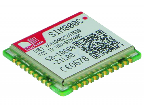
Fig. 1
The first thing you notice when opening the file is the presence of a table (in which are highlighted the possible combinations that can be obtained with the jumpers on the board (corresponds to Table 1 that you find in the first episode). Depending on how they are positioned, you can select, for example, which communication interface to use, i.e. hardware or software UART with or without a serial light. Direct communication with the PC is also possible, bypassing Arduino.
Afterward, the guidelines for selecting the GSM module to be used (among those supported) begin; only one can be set at a time. To select the module, you have to uncomment the corresponding line without changing the others:
#define SIMCOM_SIM800C // Use this for SIMCOM SIM800C GSM module
//#define SIMCOM_SIM900 // Use this for SIMCOM SIM900 GSM module
//#define SIMCOM_SIM928A // Use this for SIMCOM SIM928A GSM module
//#define FIBOCOM_G510 // Use this for FIBOCOM G510 GSM module
//#define QUECTEL_M95 // Use this for QUECTEL M95 GSM module
The bolded line identifies the GSM module you want to use, while the others correspond to the supported but not selected modules. This concept applies to all possible selections of a single object from a list of possible choices.
The following are the guidelines for selecting the Arduino board to be used: Arduino Uno or ArduinoMega 2560 (FishinoUno and FishinoMega 2560).
The following is the selection of the hardware revision; development started with version 1.0, which obviously lost its meaning. Currently, only version R.1.2 should be selected.
Once you have defined the hardware, you have to tell the compiler whether to use the hardware or software UART interface; the second available UART, both hardware and software, is not used but remains available for future developments.
Eventually, we have to assign a unique name to the Arduino pins, whose first part concerns the hardware revision 1.0 (which is obsolete), while immediately after we find the definitions regarding the hardware revision 1.2:
• Pin definition for Arduino Uno using the “ARDUINO_UNO_REV3” directives;
• Arduino Mega 2560 pin definition using the “ARDUINO_MEGA2560_REV3” directive.
Let us remember that only one directive can be selected. In the pin list definitions, we find the UARTs’ TX and RX signals, both software and hardware, the definition of the LEDs connected to the Arduino, as well as the trigger signals.
Once the configuration of the hardware part has been completed, it is necessary to switch to the activation or deactivation of some software sections for the management of the responses received from the GSM module to the AT commands sent. As usual, directives are used. In this case, it is possible to have several sections enabled at the same time. At present we have five possible state machines, which affect:
• responses to generic AT commands, such as the AT+CFUN command;
• responses to AT commands for safety management, such as the AT+CPIN command;
• answers to AT commands to manage the phone book, such as the AT+CPBS command;
• responses to AT commands for SMS management, such as AT+CMGD;
• Answers to AT commands for handling voice calls, such as the ATA command.
So, we have the following defines:
#define ENABLE_ANSWER_GENERIC_AT_CMD_STATE
#define ENABLE_ANSWER_SECURITY_AT_CMD_STATE
#define ENABLE_ANSWER_PHONEBOOK_AT_CMD_STATE
#define ENABLE_ANSWER_SMS_AT_CMD_STATE
#define ENABLE_ANSWER_PHONIC_CALL_AT_CMD_STATE
//#define ENABLE_ANSWER_GPRS_AT_CMD_STATE
//#define ENABLE_ANSWER_HTTP_AT_CMD_STATE
For each state machine there is a unique identification code necessary for the proper management of responses; codes and definitions go hand in hand, so when you create new sections of code to manage responses to AT commands you will have to either add a definition for activating/deactivating the code, or assign a unique code to the new section. Below are the codes already assigned in the library:
#define ANSWER_GENERIC_AT_CMD_STATE 0
#define ANSWER_SECURITY_AT_CMD_STATE 1
#define ANSWER_PHONEBOOK_AT_CMD_STATE 2
#define ANSWER_SMS_AT_CMD_STATE 3
#define ANSWER_PHONIC_CALL_AT_CMD_STATE 4
#define ANSWER_GPRS_AT_CMD_STATE 5
#define ANSWER_HTTP_AT_CMD_STATE 6
The last section contains debugging directives, which enable/disable code sections within the library for debugging sent AT commands and their responses, data flow on the selected serial, ON/OFF/RESET of the connected GSM module and management of AT safety commands.
The debug information is printed on the Arduino IDE serial monitor using the default serial connection so, from your code, you must enable the serial debug at the desired speed and set the serial monitor accordingly.
Having said that, we have the global directive “DEBUG_MODE” which has the function of MASTER and if commented, it disables the entire debug code in the library. A series of SLAVE directives follow to select what you obviously want to debug with the active MASTER directive. Hence, we have the following directives:
• “UART_DEBUG” to check the serial connection status, that is:
– Idle = waiting to do something;
– Send = sending data in progress;
– Wait = waiting for a response from the GSM module;
– Overflow = Overflow detected;
• “GSM_CMD_DEBUG_AT_CMD” for the analysis of data sent to the GSM module and related responses (the debug mode also intercepts strings received autonomously from the module);
• “GSM_CMD_DEBUG_ON_OFF” for the analysis of the actions of power ON, power OFF and RESET of the GSM module;
• “GSM_SECURITY_DEBUG” for the analysis of the PIN and PUK management functions of the SIM card.
For each of the listed directives, there are code sections scattered throughout the library; each one is associated with the additional text to identify/understand what is being displayed on the serial monitor.
All debugging text is stored in the microcontroller’s FLASH memory to save valuable SRAM memory. Remember also that entering the debug code occupies a certain memory space in the FLASH which must be taken into account, especially if you use Arduino Uno.
At the file end, we find variable and function declarations; in this case, there are only:
• a function for the configuration of the Arduino I/O for the management of the LEDs (hardware 1.2 and Arduino Mega 2560 (void SetOutputLed(void) required); it can be recalled from any sketch and is not required to pass parameters to it;
• a function for the configuration of Arduino I/O for the management of triggers (void SetOutputTrigger(void)); it can be recalled from any sketch and it is not required to pass parameters to it;
• a function to check the LEDs connected to the Arduino, to be used as a test during initialization; hardware 1.2 and Arduino Mega 2560 (void CheckOutputLed(void)) are required; the function can be recalled from any sketch and is not required to pass parameters to it;
• a function to check triggers connected to Arduino, to be used as a test during initialization (void CheckOutputTrigger(void)); the function can be called from any sketch and is not required to pass parameters to it;
• a function to turn on the LED connected to the Arduino; hardware 1.2 and Arduino Mega 2560 are required (void LedOn(uint8_t LedSelected)); it can be recalled from any sketch but requires as parameter the number of I/Os to which the LED is connected (e.g. PIN_LED4 );
• a function to switch off the LED connected to the Arduino; hardware 1.2 and Arduino Mega 2560 are required (void LedOff(uint8_t LedSelected)); the function can be recalled from any sketch and requires as parameter the number of I/Os to which the LED is connected (for example PIN_LED4);
These are followed by two functions for the triggers management (void TriggerOn(uint8_t TriggerSelected) and void TriggerOff(uint8_t TriggerSelected)); both can be recalled from any sketch and require as parameter the number of I/Os to which the trigger is connected: for example TRIGGER_1 .
Finally, a function has been defined for flashing an LED among those connected to the I/O of the Arduino board (void LedBlink(uint8_t LedSelected, uint8_t DutyCycle, uint8_t TimeOutConstant)); the function can be recalled from any sketch and requires three parameters:
– I/O to which the LED is connected (e.g. PIN_LED4);
– duty-cycle flashing (e.g. 50%);
– the time constant, corresponding to the period of the square wave that drives the LED (for example 250ms corresponds to T_250MSEC.
The functions described above can then be called up in the sketches in order to have feedback of situations, such as the reception / sending of an SMS, the reception of a voice call, etc. E.g., let’s suppose that during the initialization phase we decided to use the flashing function to indicate that the GSM module is being initialized, the LED will stop flashing only after initialization is complete. The flashing function applies to both LEDs and triggers.
After this preamble, we go back to the file “GenericCmd_GSM.cpp” and analyze how it works to send a generic AT command, so we will not deal with the initialization for now, or any decoding of the GSM module response.
We analyze the sending of the command AT+CFUN, which requires a parameter that sets the level of functionality of the GSM module that is:
• 0 = minimum functionality;
• 1 = full functionality;
• 4 = RF transmission and reception stages disability.
The function is declared as uint8_t GenericCmd_GSM::SetCmd_AT_CFUN(uint8_t FUN_Code) and has as parameter the code to pass to the considered AT command; it returns 0 if it did not send the required AT command and 1 if the command was sent successfully.
Before sending the AT command the function:
• resets the data transmission/receipt buffer to zero;
• saves the received parameters in case it tries to send the AT command again in case of problems (it tries to send the command for a maximum of three times);
• sets a flag that identifies that the AT command sending process is starting;
• resets all other management flags.
Once this is done, the function is ready to compose the AT command to be sent and then reads from FLASH the AT command to be sent, in this case, AT+CFUN. Remember that all AT commands used are stored in the FLASH, for those who need parameters, these will be added at the end of the command. Reading the AT command from FLASH, the system adds the necessary parameter in the queue and updates a variable containing the length of the AT command to be sent (remember that the AT command is a string). This variable is used by the serial management function to understand when it has finished sending all the bytes (chars) that make up the command.
Finally, it calls up a function for initialization of the machine in states for sending the command itself:
Gsm.StartSendData(CMD_IDLE, WAIT_ANSWER_CMD_AT_CFUN, ANSWER_GENERIC_AT_CMD_STATE);
This function sets the IDLE status for this commands’ category, the wait status for the GSM module to wait for the response and, finally, the category to which the command belongs, which in this case is part of the generic ones. A typical AT command sending function is done as in Listing 1.
How does the system start sending the AT command? To do this, a special function void Uart_GSM::ExecuteUartState (void) has been set up, which is continuously called in the void loop cycle of the sketch (Gsm.ExecuteUartState()). In this function, we have a state machine, made with a switch construct, which is always in IDLE mode until it notices that the flag UartFlag.Bit.SendData has not gone to 1 and the variable containing the length of the AT command to be sent is greater than 0. When these two conditions are verified the system goes into the state of sending command or UART_SENDDATA_STATE. As soon as this new state is executed, the data in the transmission buffer is sent to the active serial at the set speed, the system then sets a new state of waiting for the response from the GSM module or UART_WAITDATA_STATE. In this new state, the system waits for a response from the GSM module; the status is finished if there is no more data available for reception or if a reception time-out expires. Once reception is complete, the IDLE status is set again. Fig. 2 shows the operation of the state-controlled machines for sending/receiving serial data. Within the functions that make up the UART communication management status machine, we find the presence of conditional code that is activated and compiled only if the directives mentioned above are active, such as those to activate the serial debug code. Currently, only UART1 is used and also for this there are guidelines for activating and compiling the necessary code when using UART1 hardware or software.
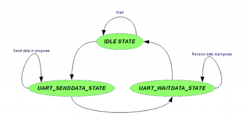
Fig. 2
Another fundamental function for the management of responses by the GSM module to AT commands sent is the following:
Gsm.GsmAnswerStateProcess();
This function is continuously recalled in the void loop() cycle of the sketch. It aims to call up the right function to decode the replies received from the GSM module. There are, for the time being, seven possible cases related to the different categories of AT commands into which we have divided the library. For each of them, a directive has been defined to activate the corresponding code and then make it available to the compiler.
The function that deals with decoding the response received from the GSM module to the command sent before (AT+CFUN) are:
Gsm.GsmGenericWaitAnswer();
The function performs a series of tests in order to be sure that it is possible to start decoding the data received about the command sent and that therefore there are still no slopes to be completed. Then you make sure that there is data in the buffer by running a test on the variable ReadPointer which indicates how many bytes have been received from the serial port.
The value must be greater than zero for the function to begin decoding the response.
The second test checks that within the received string there is the word “OK” which indicates that the AT command has been received, understood and executed. Depending on the command sent, there may be only the wording “OK” or even a series of parameters in response to the request made. For example, if the AT command sent had been AT+CREG? the response received would have contained not only the wording “OK” but also the following possible string: +CREG: 2,1,”0065″,”16F3″.
Having said this, the code, once verified that in the string there is the word “OK”, proceeds with the subsequent decoding of what has been received using the construct switch to which you must pass the code of the AT command sent.
Each AT command is coded with a unique code as mentioned above. In the case of the AT+CFUN command, the system does not perform any other operation as there are no parameters to be decoded in the response.
If the command sent had been AT+CREG? the system would have decoded the data present in the response and saved in a special data structure called CREG_Info. One of the information that is extrapolated from the response is the connection status, which is saved in the variable CREG_Info.Stat.
The connection status can be:
• “0” = not registered;
• “1” = recorded;
• “2” = looking for an operator to register for;
• “3” = registration denied;
• “4” = unknown;
• “5” = registered as roaming.
Other two extrapolated information are the “location area code” or more simply “lac” and the “Cell ID” or more simply “ci”; this information is saved in the two variables CREG_Info.LAC_Info and CREG_Info.CI_Info.
There are two other basic functions: the first “listens” on the serial port and if independent data packets arrive from the AT commands sent, it intercepts and sends them to the reception buffer (Gsm.UartContinuouslyRead(); ). This data is called “Unsolicited Result Code” and is information that the GSM module automatically sends as a result of events occurring on the GSM network, such as a cell change, a disconnection, etc.
The second function (Gsm.ProcessUnsolicitedCode(); ), on the other hand, decodes the data received from the previous function; it is currently able to decode the “Unsolicited Result Code” concerning SMS, voice calls and the connection state to the cell.
So we can summarize that the code needed in the void loop() loop of the sketch is as follows:
Gsm.ExecuteUartState();
if (Gsm.GsmFlag.Bit.GsmInitInProgress == 1) {
InitGsmSendCmd();
InitGsmWaitAnswer();
else {
Gsm.UartContinuouslyRead();
ProcessUnsolicitedCode();
Gsm.GsmAnswerStateProcess();
}
As you can see, we find the functions we have described before; the construct “if else” is used to understand if the system is initializing the GSM module; in this case only the following functions will be called:
InitGsmSendCmd();
InitGsmWaitAnswer();
The first sends the AT initialization command, the second waits for and decodes the response from the GSM module.
MODULE INITIALIZATION
We just have to describe the GSM module initialization process: the initialization cycle starts from the void setup() of the sketch, calling the function Gsm.InitPowerON_GSM() which configures the machine to states of sending commands initialization and the machine to states of sending steady commands, the latter is put in IDLE mode until the end of the initialization.
The first step is the power on of the GSM module by means of a special impulse, which is followed by the waiting for a response; this is because when the GSM module is switched on it always responds, unless otherwise programmed, with a string indicating that the power on was successful. They usually respond with a string like “RDY”, SIMCOM and QUECTEL modules, or with “AT command ready” for FIBOCOM. If the module responds like this, it means that the ignition has been successful and that you can move on to the next step, otherwise the following may have happened:
• the GSM module was already on and therefore was turned off; this is clear why the module sent the string “NORMAL POWER DOWN”; (this applies to SIMCOM and QUECTEL) and in this case the system re-proposes the power on command;
• If you do not receive any response, it may be because the GSM module is either off (FIBOCOM) or needs to synchronize the speed of the serial via autobaud and then you must send the command AT until the synchronization takes place;
In both cases, the system is able to react. Once the GSM module has been switched on, the system sends a series of AT initialization commands, followed by the sequence of commands sent:
• AT&F0 = Returns parameters to factory values;
• ATE0 = disables “Echo mode”;
• ATQ0 = sets the system to receive the “result code” from the GSM module; for example the code “OK” after sending a successful command or “ERROR” for a wrong or not understood command (we recommend to have this function active);
• ATV1 = sets the format of the reply sent by the GSM module; in our case we set the “verbose code” (used in our library) in order to receive text strings and not simple numeric codes (for example “OK”, “CONNECT”, “ERROR”, “BUSY”);
• AT+CMEE = sets the format that must have the error codes reported by the GSM module, in which case our library is set to receive error codes in numerical format only, which will be decoded by the library (you can disable this function, but is not recommended, or set it to receive errors in “verbose < err> “);
• AT+IPR = the serial speed is no longer fixed at 57600 but the autobaud is set;
• AT+ICF = sets serial communication with 8 data bits, 0 parity bits and 1 stop bit;
• AT+IFC = disables data flow control;
• AT+CPIN? = check if you need to enter the PIN code to unlock the SIM card;
• AT+SPIC = if the SIM requires the PIN code, the system checks how many attempts are still left before sending it, since sending the wrong PIN three times disables its operation until you enter the PUK code; if less than two attempts remain, it does not send the PIN;
• AT+CPIN = sends to the SIM the PIN stored in the microcontroller EEPROM; if the PIN sent to the SIM is wrong, the GSM module returns the error code 16 and the initialization algorithm intercepts this anomaly, interrupting the initialization itself;
• AT+CLVL = sets the volume of the spk output;
• AT+CMIC = sets the microphone input gain;
• AT+CRC = enables the CRC (Cellular Result Code) parameter in the extended format, so when you receive a voice call the GSM module will send the code “+CRING: VOICE” instead of the string “RING”;
• AT+CLIP = enables the Calling Line Identity (CLI) parameter so that during an incoming voice call the caller’s phone number is displayed, which is useful in applications with phone number discrimination;
• AT+CMGF = sets the SMS format; the library uses the Text Mode format and does not support the PDU mode;
• AT+CSCS = sets the character set “IRA” or International Reference Alphabet;
• AT+CNMI = sets how, by means of an unsolicited result code, the receipt of an SMS by ME must be indicated; in our case:
– <mode> is set to 1, so if the communication link is busy the unsolicited result code will be discarded and not sent, otherwise, it will be immediately sent to the TE;
– <mt> is set to 1, so when you receive an SMS it is stored in the designated memory area, see AT+CPMS command, so the unsolicited result code sent will also contain the memory information used to store the SMS;
– < bm> is set to “0”;
– < ds> is set to “0”;
– < bfr> is set to “0”.
• AT+CPMS = sets the memory areas in which sent and received SMS are to be saved; the library works with “SM” memory (SIM message storage);
• AT+CSMP = sets the validity period of the SMS sent or stored in the memory areas;
• AT+CREG = enables network registration and the ability to retrieve information about the cell you are connected to either through unsolicited result code or through direct reading.
Remember that when the AT+SPIC command is executed, if the number of attempts available to send the PIN code is less than 2, the process is interrupted, because there are no automatisms for sending the PUK code; this must be entered manually, for example using the serial connection to the PC or using a mobile phone.
When initialization is complete, the system resets the flag indicating initialization in progress (Gsm.GsmFlag.Bit.GsmInitInProgress), thus enabling the system to send AT commands to manage its application.
When an AT command is sent to the GSM module, both during initialization and when sending a generic AT command, there is a possibility that this may not be understood by the module. On the basis of the response received or not received by the GSM module, it retries up to a maximum of three times the sending of the AT command; if after the three attempts to send the command is not received then the system will reset the module itself and this involves the GSM module re-initialization.
If the GSM module returns error codes these will be decoded by the function:
ProcessGsmError();
For each of the error codes managed there is a corresponding flag to indicate the detection, it will then be the user’s responsibility to manage the flags in a consistent-with-their-application manner.
There are currently four categories of identifiable error codes:
• General: to be found under Gsm.GsmFlag or under Gsm.SimFlag;
• Security: found under Security.SecurityFlag;
• Calendar: can be found under PhoneBook.PhoneBookFlag;
• Messages: can be found under Sms.SmsFlag.
The file “GenericCmd_GSM.cpp” in addition to the initialization section has a number of functions for sending a series of AT commands selected with the intention of facilitating the development of applications “GSM oriented”. At the moment we do not cover all possible situations but with time we think we can reach a good compromise between implemented functions and necessary management code, especially for decoding the responses received by the GSM module. Among the features currently supported by the file “GenericCmd_GSM.cpp”, we have:
• Generic AT command, the function must be passed the length of the command string as a parameter. It is still under development, especially with regard to response management (Gsm.SetCmd(uint8_t Lenght)).
• AT command to switch off GSM module via software, which differs between SimCom, Quectel or FIBOCOM; in the case of Quectel also needs a parameter that if “0” means that you have to do an urgent power down and then as a response to the command is sent only “OK”, while if “1” means that you have to do a normal power down and then as a response you receive the string “NORMAL POWER DOWN” (Gsm.SetCmd_SwPowerDown(uint8_t Type)).
• Command to switch off GSM module from hardware (by a pulse of appropriate duration) or Gsm.SetCmd_SetCmd_HwPowerDown(void); ).
• AT command for function setting (Gsm.SetCmd_AT_CFUN(uint8_t FUN_Code)).
• AT command for reading or setting the date and time; it has a Boolean parameter to indicate if you are reading the date and time or if you are setting it. If “true” it reads if “false” it writes. The date and time are formatted in a string for both reading and writing. The formatting of the string is “yy/MM/dd,hh:mm:ss±zz” i.e. year, month, day, hours, minutes, seconds and the time zone that can range from -48 to +48. The time zone indicates the difference, expressed in quarters of an hour, between the time and the local date with respect to the GMT. Time zones are defined in relation to GMT, with a positive integer if late or a negative integer if early (Gsm.SetCmd_AT_CCLK(bool Query)). The library has a data structure that, thanks to a 64bit “union”, allows you to set or read the date and time values and is composed as follows:
˚ struct {
union Flag {
uint64_t ClockLong;
struct {uint8_t Year :7; // Year: 00 - 99
uint8_t Month :4; // Month: 01 - 12
uint8_t Day :5; // Day: 01 - 31
uint8_t Hours :5; // Hours: 00 - 23
uint8_t Minutes :6; // Minutes: 00 - 59
uint8_t Seconds :6; // Minutes: 00 - 59
int8_t GMT :7; // GMT: -47 ... +48
uint8_t Free :24;
} Bit;
} Clock;
} Clock_Info;
Then the user in case of date and time setting must first fill in the fields of the data structure and then call the function Gsm.SetCmd_AT_CCLK(bool Query). On the other hand, if you perform a reading, you will find these fields filled in with the data read by the GSM module.
• AT command to read the manufacturer code: it exists in two formats between which the command string varies depending on the version V25 or 3GPP, and therefore needs a parameter to identify which format to use: “0” format V25, “1” format 3GPP. In the corresponding .h file are defined the constants for this type of command (Gsm.SetCmd_ATQ_GMI(uint8_t FormatAt)). The read data is saved using the data structure ME_Info
• AT command to read the model code of the GSM module. The considerations made for the command version you want to use apply (Gsm.SetCmd_ATQ_GMM(uint8_t FormatAt)).
• AT command to read the software revision loaded in the GSM module. The considerations made for the command version to be used (Gsm.SetCmd_ATQ_GMR(uint8_t FormatAt)) apply.
• AT command to read the IMEI code (serial identification number). The considerations made for the command version to be used (Gsm.SetCmd_ATQ_GSN(uint8_t FormatAt)) apply.
• AT command to read the information concerning the registration of the GSM module to the network (Gsm.SetCmd_ATQ_CREG(volid)). The AT command receives up to three parameters as a response:
– <n> = shows the code with which the command has been configured or “0” indicates that you have disabled the registration to the network, “1” that you have enabled the registration to the network and activated the unsolicited result code regarding the connection status < stat> and finally “2” that is enabled the registration to the network and activated the unsolicited result code regarding the connection status < stat> and the location information < lac> and <ci>; during the initialization of the module is sent the command AT+CREG=2 so as to have all the possible information on the status of registration to the GSM network;
– < stat> = indicates the status of the recording to the GSM network. Possible values are: “0” not registered on the network and no other operator search, “1” registered on the GSM network with its own operator, “3” not registered, “4” unknown and finally “5” registered on the network but roaming;
– < lac> = hexadecimal code in string format that identifies the location;
– <ci> = hexadecimal code in string format that identifies the code of the cell to which you are connected.
This information is made available by the CREG_Info data structure which also, thanks to a “union”, allows us to group more information together and make it available in an easy way to the user.
• AT command to read the GSM signal strength (Gsm.SetCmd_ATQ_CSQ(volid)) which answers with the following two parameters:
– < rssi> = if it returns values like “0” and “1” it means that the GSM signal is very weak or absent. Values between “2” and “30” show a weak to the good signal situation. If, on the other hand, it reports a value of “31”, it means that the signal is very good. If it returns “99” it identifies an unknown or unmeasurable condition. Negative values in dBm are associated with the above numbers, where less than -101dBm means very weak signal, values between -100dBm and -91dBm identify the weak signal, while between -91dBm and -81dBm the signal is medium and from -80dBm up the signal is good or very good.
– <ber> = this parameter identifies a percentage value between “0” and “7” and is called “bit error rating”. If it returns the value “99” it identifies an unknown or unmeasurable condition. This information is recorded in the CSQ_Info data structure accessible to the user.
• AT command to read the name of the operator who answers with the following two parameters:
– <mode> = indicates the operating mode. Then “0” automatic mode, “1” manual mode, “2” manual de-recording from the network, “3” sets only the parameter <format> and finally “4” automatic and manual mode active. If the manual mode fails, the automatic mode is activated automatically:
– <format> = this parameter sets the format that the field < oper> should have. Then if “0” alphanumeric format long up to a maximum of 16 characters, if “1” short alphanumeric format and finally if “2” numeric format;
<mode> = this parameter shows the operator you are connected to.
The acquired information is saved in the SimFlag data structure, in particular under the headings OperatorSelMode and OperatorSelFormat, while the name of the operator is saved in the OperatorName array.
• AT command to check the status of the GSM module; in other words, it is used to see if it is busy making a voice call or other. This may be useful before sending certain AT commands (Gsm.SetCmd_ATQ_CPAS(volid)). The answer is a parameter called <pas> that can assume the following numerical values: “0” ready to receive any AT command, “2” unknown state (it is not said that the GSM module (ME) responds to a possible command), “3” active ringing (someone is calling or has received an SMS) and finally “4” voice call in progress. The above values are saved in the SimFlag data structure and in particular under the heading PhoneActivityStatus.
• AT command to set the speaker volume level, the command requires a parameter that indicates the volume level you want to set. The permitted values range from 0 to 100 for SimCom and Quectel models and from 0 to 6 for FIBOCOM. During initialization, the values are set to 90 for SimCom and Quectel models and 6 for FIBOCOM. (Gsm.SetCmd_AT_CLVL(uint8_t FormatAt))
• Finally, we have an AT command to set the gain level of the microphone connected to the GSM module. The command requires two parameters: the channel and the gain level, this for the SimCom and Quectel modules. Instead, FIBOCOM has only the gain level. So, we have that:
– < channel> : This parameter (SIMCOM) can assume the values: “0” main audio channel, “1” auxiliary audio channel, “2” main audio channel in “hand free” mode and “3” auxiliary audio channel in “hand free” mode. For Quectel the possible values are “0” normal microphone, “1” headset microphone and “2” speaker microphone. As far as FIBOCOM is concerned, this parameter loses its meaning
– < gainlevel> : This parameter indicates the microphone gain level and for all three GSM module families the possible values range from 0 to 15.
The function to use is therefore Gsm.SetCmd_AT_CMIC(uint8_t Channel, uint8_t GainLevel)).
SMS MANAGEMENT COMMANDS
We have therefore covered the AT commands available in the file “GenericCmd_GSM.cpp” and we are now ready to move on and analyze the other library files, starting with “SmsCmd_GSM.cpp” for the SMS management.
• AT command to select where to store the SMS: it can be used both to read the current configuration and to set the three memory areas; in the latter case, it requires three parameters. The function that calls this command also needs the fourth parameter to distinguish if you want to read the configuration rather than write parameters (Sms.SetCmd_AT_CPMS(uint8_t TypeOfMem1, uint8_t TypeOfMem2, uint8_t TypeOfMem3, bool Query)). So we have:
– <TypeOfMem1> = memory area 1, which is used for reading or deleting SMS messages (the three areas are <SM>, SIM resident, <ME>, GSM/GPRS resident and <MT> indicating all memory areas associated with a GSM/GPRS device, i.e. if both SM and ME are available, MT refers to both;
– <TypeOfMem2> = memory area 2; is used when sending SMS previously stored through the command AT+CMSS; the storage to be sent is done with the command AT+CMGW and the three possible memory areas are always SM and ME;
– <TypeOfMem3> = memory area 3, used to save the new received SMS; it depends on the AT+CNMI command sent during the initialization phase of the GSM module; the memory areas are those explained above.
• AT command to delete SMS (Sms.SetCmd_AT_CMGD(uint8_t Index, uint8_t DelFlag)); it requires two parameters:
– <Index> = memory location you want to delete;
– < DelFlag> = command to execute, i.e.:
– “0” deletes the SMS to the location specified with the previous parameter;
– “1” deletes all messages read with the AT+CPMS command from the specified memory;
– “2” deletes all messages already read or sent but not those to be read or sent;
– “3” deletes all messages already read, sent and also those still to be sent;
– “4” deletes all messages indiscriminately.
• AT command to read the received SMS (Sms.SetCmd_AT_CMGR(uint8_t Index, uint8_t Mode)); also this requires two parameters:
– <Index> = memory location you want to read;
– <Mode> = is used to change or not the status of the read message, i.e. if the value passed is “0” the status of the read message is changed from “REC UNREAD” to “REC READ”, while if you pass the value “1” the status of the read message is not changed.
The response is processed in order to collect information about the SMS received and especially the text of the message. Other information is the phone number from which it came and the status of the message or “REC UNREAD”. (yet to be read) or ‘REC READ’. (already read).
• AT command to send an SMS to a given phone number (Sms.SetCmd_AT_CMGS(void)); do not pass parameters because both the phone number and the text of the message to be sent are contained in two arrays that must be initialized before calling the send command. The phone number is in the “PhoneBook.PhoneNumber” array while the message text is in the “Sms.SmsText” array. A text message is sent in two distinct phases: in the first phase, the telephone number to which the message is to be sent is sent to the GSM module. Once the form returns the symbol “> ” means that you can proceed with sending the string containing the message to be sent. The two phases are automatically managed by the library; we just have to worry about initializing the two arrays.
• AT command to write a message to be sent to the memory among those chosen with the AT+CPMS command (Sms.SetCmd_AT_CMGW(void)). This command behaves exactly like the previous one except that the SMS is not sent but stored in the memory of ME. Hence, the user has to worry about initializing the array with the phone number and the array with the text to be saved. The arrays are the same as in the previous command.
• AT command to send a message saved in the memory selected with the previous command (Sms.SetCmd_AT_CMSS(uint8_t Index)). In this case, the parameter to be changed is the memory location in which it is stored.
Note that when the read command is executed, the GSM module returns the following parameters:
– <Mem1> = Memory type; SM, ME or MT;
– <Used1> = memory locations occupied;
– <Total1> = total memory locations available; since these are three, the parameters described above are also repeated for memory 2 and 3. The read values are saved in a special data structure, one for each memory. For example, for memory 1 we have the data structure “Sms_Mem1_Storage” which provides the items “Type”, “Used” and “Total”.
With this overview we have shown the AT commands available for the library file “SmsCmd_GSM.cpp”, remember that there is the equivalent file .h containing the declarations of functions, variables and data structures as well as AT commands saved in FLASH and used by the library. Remember to activate the section for the management of responses by the GSM module (ME) through the directive “ANSWER_SMS_AT_CMD_STATE_AT” in the file “Io_GSM.h”.
VOICE CALL MANAGEMENT COMMANDS
Let’s move on to a library file that handles both incoming and outgoing calls. The file is “PhonicCallCmd_GSM.cpp” and provides the following commands.
• AT command to answer (PhonicCall.SetCmd_ATA(void)). It does not require the passage of parameters and the system realizes that a call is coming because two distinct factors intervene. The first is the interrupt generated by the RI signal connected to the INT0 on the Arduino Uno board or INT4 on the Arduino Mega 2560 board. The RI signal is active at 0 logic and therefore the interrupt has been set to be activated when the signal goes from the high logic level (IDLE) to the low logic level or in other words using the downward edge of the signal.
During interrupt management, serial reception is activated to capture the sent string as unsolicited result code, which is processed by the Gsm.ProcessUnsolicitedCode() function; as previously discussed. A flag of the Gsm.GsmFlag data structure and in particular the flag Gsm.GsmFlag.Bit.IncomingCall is then set. It is your responsibility to check this bit and decide whether or not to answer the incoming voice call.
• AT command to close the current call (PhonicCall.SetCmd_ATH(uint8_t Index)). This AT command requires a parameter if the module is a SIM900, SIM928A or M95. The parameter under consideration is defined as <n> and usually, the value “0” is passed. However, there are other cases in which it may be necessary to pass values other than “0” but that we currently do not use with our library. If you want to know more, consult the datasheet of the GSM module that implements and supports these additional codes.
• AT command to initiate an outgoing voice call (PhonicCall.SetCmd_ATD(void)), this command does not need parameters as the phone number to be passed to the command is loaded into the appropriate array “PhoneBook.PhoneNumber”. Before calling up this command it is advisable to check that the GSM module (ME) is not already occupied in another voice call using the AT+CPAS command already discussed above.
• AT command to initiate an outgoing voice call using a phone number in the phonebook (PhonicCall.SetCmd_ATD_PhoneNumberMemory(uint8_t n)). This command requires a parameter to indicate which memory location contains the phone number to use.
• AT command to initiate an outgoing voice call using the phone number of the previous voice call (PhonicCall.SetCmd_ATDL(void)), no parameter required for this command.
About the library file “PhonicCallCmd_GSM.cpp” we remind you that there is the equivalent .h file containing the declarations of functions, variables and data structures as well as AT commands saved in FLASH and used by the library. Remember to activate the GSM module response management section using the “ANSWER_PHONIC_CALL_AT_CMD_STATE” directive in the “Io_GSM.h” file.
PHONE BOOK MANAGEMENT COMMANDS
Now let’s look at the library that manages the phone book. The associated file is “PhoneBookCmd_GSM.cpp” which provides the commands described below.
• AT command to select the memory to be used for the phone book, is similar to the command used to select the memories to be used for storing SMS. The command includes a parameter to indicate on which type of memory you want to work (PhoneBookCmd_GSM.SetCmd_AT_CPBS(uint8_t TypeOfPhoneBook. bool Query)):
< storage> = data string indicating the type of memory to be used, which can be:
– <DC> = (ME), containing the list of calls made; the AT+CPBW command is not applicable;
– <EN> = (SIM), memory containing emergency numbers; the AT+CPBW command is not applicable to this type of memory;
– <FD> = (SIM) memory that contains the phone numbers that the user can call; it is used to prevent you from making calls to unwanted numbers, so all phone numbers that are not in this list can not be called (excluding emergency numbers and incoming calls);
– <MC> = (MT) contains the list of telephone numbers of missed calls; the AT+CPBW command is not applicable to this type of memory;
– <ON> = (SIM) contains the list of your phone numbers;
– <RC> = (MT) contains the list of telephone numbers of received calls; the AT+CPBW command is not applicable to this type of memory;
– <SM> = (SIM) is the phone book of the SIM and you can save the desired phone numbers in your application;
– <LA> = last number of any list;
– <ME> = (ME) is the phone book of the GSM module and you can save the desired phone numbers for your application;
– <BN> = (SIM) phonebook numbers excluded;
– <SD> = (SIM) phonebook service numbers;
– <VM> = (SIM) phonebook voice mail numbers;
– <LD> = (SIM) last phonebook.
In our application, we use SM memory to store your favorite phone numbers. Currently, the ability to manage FD memory is not supported as it requires an additional parameter, i.e. an access password also called PIN2.
The parameter to pass to the AT command is of string type, while to our function we have to pass an integer number without a sign that identifies which memory we want to use as decoded in the associated file .h. There will then be a function that will extrapolate the right string given the assigned code. If you want to use the command in read the query parameter must be true, so the command will return a series of information about the memory currently in use: type of memory, number of locations used and the total number of locations.
The read data is saved in the PhoneBook.PhoneBookFlag data structure.
• AT command to read the phone book at the desired location; it has a parameter to indicate on which type of memory to work (PhoneBookCmd_GSM.SetCmd_AT_CPBR(uint8_t Index. bool Query)):
– < index> = index of the address book to be read; this command returns parameters including:
– < index> = index of the address book;
– < number> = phone number in the phone book at the given index;
– < type> = type of number stored; if 161 national number, if 145 international number (Use the “+” symbol at the top of the number followed by the international code);
– <text> = short description assigned to the saved number.
The read data is saved in three variables, the first two of which are arrays, PhoneText – PhoneNumber – PhoneNumberType.
• Finally we have the AT command to write a phone number to the selected address book (PhoneBookCmd_GSM.SetCmd_AT_CPBW(uint8_t Index. uint8_t CmdType. uint8_t PhoneNumberType)). The parameters to be passed to the AT command are:
– < index> : Index of the address book you want to write to
– < number> : Phone number to be saved in the phone book
– < type> : Number type, see previous AT command
– <text> : Text to assign to the saved number. For example, name and surname
The telephone number and the associated text must be stored in the appropriate arrays discussed before so that they can be inserted in the appropriate spaces during the composition of the AT command.
The function must then pass the index on which you want to save the phone number, the type of the national/international phone number and then a parameter that identifies the type of command you want to execute: write the new phone number in the selected address book or delete the phone number from the selected address book. In the .h file, we have encoded unique codes that identify the write or delete command. This code must be passed to the function described. When deleting a phone number from the phonebook, the AT command has only the index as a parameter.
We have also completed the description of the AT commands available for the library file “PhoneBookCmd_GSM.cpp”; here too there is the equivalent .h file containing the declarations of functions, variables and data structures as well as the AT commands saved in FLASH and used by the library. Remember to activate the GSM module response management section using the “ANSWER_PHONEBOOK_AT_CMD_STATE” directive in the “Io_GSM.h” file.
SAFETY MANAGEMENT COMMANDS
We are going to end this guide introducing you to the library that deals with the management of commands related to security, i.e. the management of passwords, PINs, etc. The associated file is “SecurityCmd_GSM.cpp” and provides the following commands.
• AT command to check how many times the PIN/PUK code has been entered without success compared to the number of attempts allowed. This command differs in syntax between the three different manufacturers SIMCOM, FIBOCOM and QUECTEL. We then have (SecurityCall.SetCmd_ATQ_SPIC(void)) for SIMCOM, (SecurityCall.SetCmd_ATQ_TPIN(void)) for FIBOCOM and (SecurityCall.SetCmd_ATQ_QRTPIN(void)) for QUECTEL. In all cases, no parameters must be passed to the AT command, only the correct AT command must be used depending on the GSM module selected. As a response from the GSM module (ME) you get the attempts already made for <pin1>, <pin2>, <puk1> and <puk2>.
These values are then stored in the SecurityFlag data structure, precisely in SecurityFlag.Bit.PinRetry, SecurityFlag.Bit.Pin2Retry, SecurityFlag.Bit.PukRetry and SecurityFlag.Bit.Puk2Retry. It is then up to the user to use the read values to decide whether or not to attempt to send the PIN or PUK code. We want to remember you that this mechanism is used during the initialization as already widely explained before
• AT command to check if the PIN code is required to unlock the SIM (SecurityCall.SetCmd_ATQ_CPIN(void)). The command does not require any parameters. As a response from the module we have the following:
– <READY> : ME does not require a PIN code. No action to be taken
– <SIM PIN> : ME is waiting for the PIN code. Therefore, before sending the PIN code, it is advisable to use the AT command described above to check how many attempts are available and then, if necessary, send the PIN code. Please note that the PIN and PUK codes are saved in EEPROM
– <SIM PUK> : ME is waiting for the PUK code
– <PH SIM PIN> : ME is waiting for the anti-theft PIN code
– <PH SIM PUK> : ME is waiting for the PUK code burglar alarm
– <SIM PIN2> : ME is waiting for the PIN2 code. Must be explicitly requested via the error code CME 17
– <SIM PUK2> : ME is waiting for the PUK2 code. Must be explicitly requested via the error code CME 18
• AT command for sending the PIN or PUK code (SecurityCall.SetCmd_CPIN_PUK(uint8_t TypeOfCmd)). This AT command expects the PIN code or the PUK code followed by the new PIN code, then the function must be passed the action code you want to perform or only PIN code or PUK code plus PIN code. In the .h file, we have encoded the various operating situations. Depending on the action chosen, the function will read from the EEPROM memory the PIN code to be added to the AT command or the PUK code followed by the PIN code. You must be sure that you have saved the PIN and PUK codes in EEPROM using the appropriate sketch. Next time, we’ll show you how to do it.
• AT command to lock or unlock the available network functions with a password. The AT command requires the following parameters:
– < fac> : Network features that you want to block using a password
– <mode> : If “0” unlocks, if “1” locks, if “2” checks the status of functionality
– < passwd> : Password string format
– < class> : Class membership: “1” entry, “2” all services, “4” fax and “7” all classes
The function must be passed two parameters which will be used to compose the desired AT command (SecurityCall.SetCmd_CLCK(uint8_t TypeOfFac, uint8_t Mode)). The first parameter is a code that identifies the network functionality you want to protect with a password. The codes are encoded in the .h file while the second parameter determines whether to execute a lock, unlock or a simple read query. The possible manageable network functions are:
– <AO> : 4-Digits → Blocking all outgoing calls
– <OI> : 4-Digits → Blocking outgoing international calls
– <OX> : 4-Digits → Blocking outgoing international calls except for the country of origin
– <AI> : 4-Digits → Blocking all incoming calls
– <IR> : 4-Digit → Block all incoming calls when roaming in another country
– <AB> : 4-Digit → Blocking of all services
– <AG> : Blocking of all outgoing services
– <AC> : Blocking of all incoming services
– <FD> : SIM card memory lock containing only the phone numbers you can call
– <SC> : 4/8-Digit → Lock SIM as for the PIN
– <PN> : 8-Digit → Network personalization
– <PU> : 8-Digit → Network subset personalization
– <PP> : 8-Digit → Service Provider personalization
– <P2> : 4/8-Digit → SIM PIN 2
Each of the above codes has been coded with a unique number to be passed to the function as described above.
As the last one, we have an AT command to change the set password (SecurityCall.SetCmd_CPWD(uint8_t TypeOfFac)). The only parameter to pass to the function is the type of network functionality you want to manage. The list made in the previous command is valid, but only for: <AO>, <OI>, <OX>, <AI>, <IR>, <AB>, <P2> and, <SC>. The AT command therefore expects the following parameters:
– < fac> : Network functionality on which you want to change the password
– < old-passwd> : Old password
– <new-passwd> : New password
CONCLUSION
Well, we have deeply explained all the AT commands currently available in our GSM shield module management library.
From openstore
GSM compact interface with M95
Small Breakout for SIM928 GSM&GPS Module

[…] UNIVERSAL GSM SHIELD – The GSM library for ArduinoPosted 2 weeks ago […]