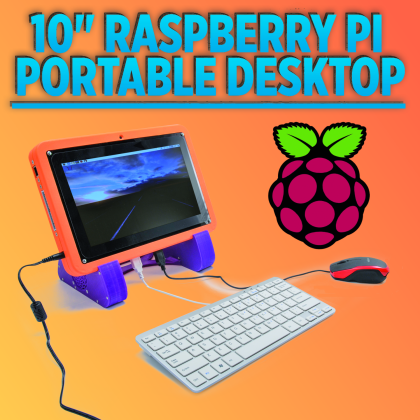
Let’s create a portable touchscreen all-in-one PC, to be used both as a portable computer and as a platform for the field development of applications, thanks to the integration of peripherals and to the access – from the outside – to Raspberry Pi’s expansion connector.
The computing power and the rich equipment of peripherals on board – that’s no mystery – make the Raspberry board a veritable Linux Personal Computer, in a miniaturized version; that’s something that those who experimented with the creation of Raspberry Pi-based laptops and all-in-one computers know well; some of these creations have been evaluated by the public and by possible investors on the main crowdfunding platforms. Raspberry Pi 3, the most recent version, has been enhanced as for the core processor and enriched with peripherals for the wireless communication (such as WiFi and BlueTooth), that make it even more similar to a computer, and in particular, to a notebook. Precisely the fact that it is always more complete, brought us to design and create a veritable portable PC by means of it; we consider it as a middle way between a tablet (strictly speaking, it is not a tablet, since it is a bit too thick and heavy) and an all-in-one PC, since it has the shape and the equipment of the latter, though it is battery-powered and operates independently, and as portable as tablets are. The only thing our device has not been supplied with are the loudspeakers – in order to limit the encumbrance – but we made up for it, by creating a base for it, one that incorporates a small 3+3 watt audio power amplifier (it is based on the PAM8403 integrated circuit, that we know already, since we used it in other projects) and two loudspeakers, one placed at each side.
The base may be left as a fixed one at your workstation, as if it were a docking-station, while when working outside and on the field you may bring the computer alone with you: if you need the sound you may always connect some headphones.
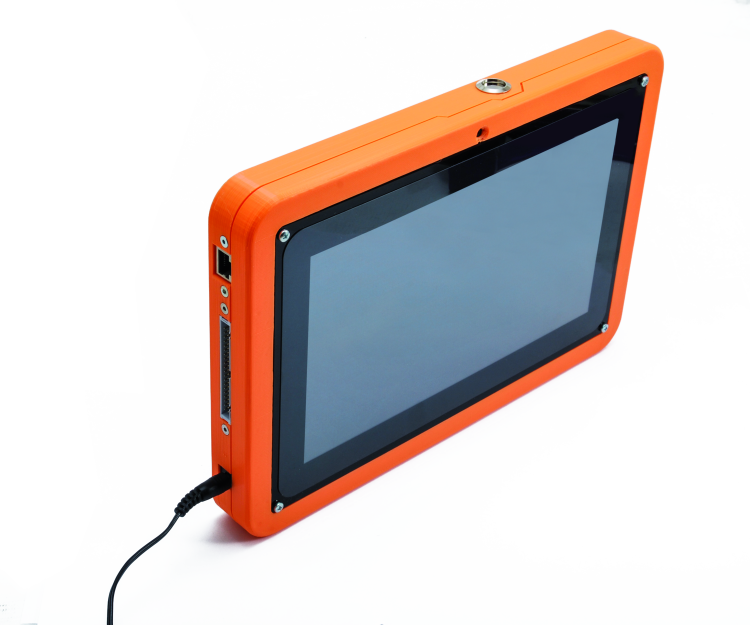
The computer we developed is supplied with touch-screen functions, USB ports and an expansion port for the purpose of organizing the access to Raspberry Pi 3’s large pin-strip, from the outside; in fact, by connecting a flat-cable between the expansion connector (GPIO) and a dedicated adapter, it is possible to return all the board’s pins on the breadboard: this opens the way to the prototyping and to the field development of any device or electronic circuit to be interfaced to Raspberry Pi.
The touch-screen function enables the usage of our mobile computer as a smart-panel for the management of automatic machinery or for the field testing of many systems that may be interfaced via Ethernet, USB, WiFi and Bluetooth.
Clearly, nothing forbids the usage of our device as a portable computer, as you would do with a tablet… Although it is a bit bulkier and heavier than a commercial tablet…
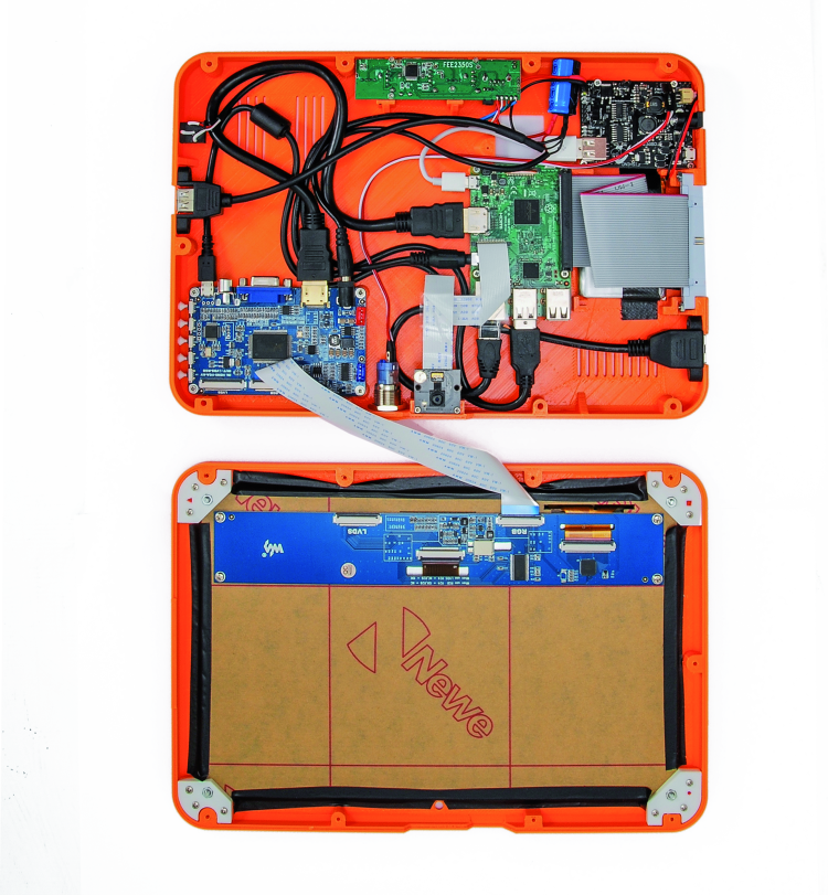
Everything is contained in a container that we 3D printed by means of our 3Drag Big printer, and that is composed of a lower cover, and of an upper one that acts as a frame for the display; of the said case we made available – in addition to the project files – the STL ones for the printing of all the parts and the elements, both for the computer and for the base.
Behind the case, there is a compartment lid for accessing Raspberry Pi’s SD-Card, so to substitute it when it is needed to boot different operating systems.

Our system
Let’s see what this is about, by analyzing the composition of this device, that incorporates (in addition to the Raspberry Pi 3):
- a USB hub, so to organize – starting from the board’s USB port – further USB 2.0 ports; four of them are found in the lower part of the computer, and three are below (they may be accessed from the bottom);
- a 10” touch-sensitive monitor kit for Raspberry Pi, including a driver board and a 39 cm long HDMI M/M cable, in addition to a 47cm long USB A male/µUSB male adapter;
- a 5 megapixel video camera for Raspberry Pi;
- a Torpedo 2 DC/DC converter board;
- a 3,7V÷4.200 mAh single cell LiPo battery;
- a 40 pin female/male ribbon cable (with the male from the panel and the female from the PCB), so to bring to the outside the pins of Raspberry Pi’s expansion connector);
- a cable having a USB A male connector at an end, and a µUSB on the other, so to power Raspberry Pi;
- another USB cable, that only draws power and makes it available on the other side of the device.
Raspberry Pi 3 integrates the WiFi and the Bluetooth interfaces, therefore further peripherals are not required.
Now, with reference to the wiring system that is shown in these pages, let’s see how our computer is made; it depends on Raspberry Pi 3, that interfaces – by means of a USB port and of the HDMI – the touchscreen display’s controller board: the USB is needed for the data exchange concerning the panel’s touch interface, while the HDMI port sends the signals to the screen’s driver section. As for the controller board’s power source, 5 volts are drawn from the cable coming from the Torpedo 2 DC/DC output and are brought by means of a cable supplied with a jack plug to the board itself, that has been supplied with a DC jack socket for the purpose.
The display that we used is a color one, having a 1,024×600 pixel resolution; the pertaining hardware supports Raspbian, Ubuntu, Windows 10 IoT. The display’s controller board is supplied with HDMI, VGA and AV (CVBS) inputs, that may be selected by means of multilanguage OSD menus and via a series of control buttons; it manages the panel by means of a flat cable on which the video signals and the ones supplied by the touch panel pass through.

In the container, the panel’s controller board is arranged so that the side with the buttons is on the right edge, so that – by means of holes that have been made for the purpose – the five buttons for the screen management may be accessed. The display’s power source passes through its controller, that is powered by 5 volt from the device’s power supply, that is to say, the Torpedo 2 board that is a DC/DC converter that may be powered by direct current having a voltage between 3.5 and 18 V, and that is capable of supplying 5 V that is perfectly stabilized and output current up to a 3 ampere, and in our case that’s enough to make things work. The power supply’s power is 36 watt.
The same Torpedo 2 board charges a battery composed of a LiPo cell, that is needed in order to power the whole, when it is disconnected from the network power supply (that’s a 12 volt – 3A wall cube switching power supply) that by means of its own cable (ending with a jack plug) is connected to our computer’s coaxial power connector. The operating time depends on the active peripherals and on the ones that have been used (WiFi and Bluetooth use quite some energy, and the display as well when the backlighting is activated); for the purpose, the software running on Raspberry Pi 3 – by relying on the reading of the power voltage that has been implemented on the board – deactivates all the peripherals that are not needed, and lowers the backlighting level after a certain idle time (intended as the period of time in which actions on the touchscreen, on the keyboard and on the USB mouse are lacking). In the case in which OSMC is the operating system, when the power supply is disconnected, since the output voltage is lowered, Raspberry Pi shows the symbol of a lightning up and on the right, on the screen. In order to give you an idea of the system operating time, we will just say that during our tests, with a continuously active Internet connection with the Ethernet cable (and therefore, with the WiFi not working), with an always operational 100% screen backlighting (and the energy saving mode deactivated), and audio units connected to the computer, kept at the maximum volume, we managed to achieve a continuous functioning – and without problems – for more than 1.5 hours.

In the project we took advantage of Torpedo 2’s Enable line, so to turn off the electronics: by connecting a switch to it, when the operating system has carried out the shutdown we disable the DC/DC output and everything is turned off (exception made, of course, for Torpedo 2). In order to restart the system, we will close the switch and Torpedo 2 will return to supplying power; we had to choose such a system, since Raspberry Pi is booted and boots the operating system only when it receives power. Once powered, it may be restarted or turned off only from the dedicated command (reboot and shutdown, respectively); once the shutdown has been carried out, however, if you wish to restart the operating system you will need to turn it off and to restart it.
The computer is provided with a video camera that is directly connected to the dedicated Raspberry Pi 3’s connector (CSI), by means of the supplied flat cable.
Torpedo 2’s + and – output powers, by means of a specific cable, the touch screen’s controller board and the cable via the USB connector that we will use, by placing it on the side of the computer case, so to power external devices, requiring 5 volt. It will be a sturdy 4.7 mF 25V electrolytic capacitor to provide for possible pulse requests of current, in addition to Torpedo 2’s nominal one. The capacitor is placed in parallel to the abovesaid output.
The other Torpedo 2’s output (that is to say, the one with the USB connector) is used in order to power – by means of a USB A to microUSB adapter cable – the Raspberry Pi 3, via the microUSB power connector of the latter.
The USB hub is connected to one of Raspberry Pi 3’s ports. The USB hub is the port expander that enables the possibility to have as much as three USB ports on the back side of the container (lower cover) and four on the bottom (the side below the cover).
Raspberry Pi 3’s audio output has been made accessible from the outside, by means of a specific cable with a 3.5 mm stereo jack plug, from the board’s side, and of a female one, on the computer’s right side, that is used in order to connect the headphones or the PC loudspeakers, or to drive a possible audio group, to be integrated in the base, and that you may create in order to support the tablet. Another USB socket on the panel is connected via a specific cable to another USB on Raspberry Pi, and is placed on the container’s left side. There is nothing else to add on the subject of this portable computer, at least for what is in the case. There is an optional audio system, that consists in a functional base that has been 3D printed in PLA, and that integrates an amplifier and “loudspeakers”, and that perfectly supports the computer.

The audio base
The base is, therefore, an integrated device that acts both as a support, and as a pair of loudspeakers; inside of it an amplifier module (based on the PAM8403 integrated circuit) is placed.
That’s a small stereo class D audio amplifier, capable of supplying a maximum power of 3+3 W at 4 ohm.

It is supplied with a potentiometer for the volume control and with an on/off switch, both are made accessible from the outside, by opportunely juxtaposing the breadboard close to the container. The circuit is powered by a voltage between 2.5 and 5.5Vcc, that enables the functioning, after having connected the power supply’s + and – contacts to a coaxial jack plug that is applied to a container side, and then by bringing the 5 volt via a specific coaxial USB A/jack cable: when you create it, please remember that the jack connector has the positive on the central contact.
The loudspeakers are 3 watt full range ones (code 2846-AP5243W) and have a 4 ohm impedance and a 52.8 mm diameter; the magnet is a big one (44.7 mm, weighing 102 g) and guarantees a high sound output. The connection is carried out as shown in figure In order to improve the stereo listening, the two transducers are to be mounted each one on a base’s side, at the group of holes enabling the soundwaves to exit.

The software
Once we showed you what the hardware consists in, let’s see the platform that has been chosen for our computer. There is a premise: given that the system core is a Raspberry Pi 3 board, we may use any operating system on it, that is to say Raspbian and derived ones, and also OSMC, that has greater multimedia capabilities, and that we already learned to know; it consists in using Raspberry Pi as a media center, in addition to a portable computer. The hardware surrounding our computer’s board is completely supported by the said operating system.
As for our application, we installed OSMC for our tests, and Raspbian PIXEL as well, that is the last version of Raspberry Pi 3’s operating system. In any case, on Raspberry’s website (www.raspberrypi.org/) you will find the complete list of the operating systems that are currently supported, with the pertaining instructions.

As for the testing of electronic devices, and in particular of circuits such as the one on the breadboard, we provided for the usage of a simple application for Raspbian, that enables the reading of logic states or the sending of signals via the expansion connector and its GPIOs. The application is named Node Red and has been specifically created for Raspberry Pi; it enables the drawing of circuits, by visually composing them in a very simple way, thanks to functional blocks that may be connected among them. Moreover, it enables to display the various GPIO connectors that have been provided for in the Raspberry Pi boards, and to connect them to the functional blocks, so to then proceed to the testing or to the circuit’s simulation.

Well, that’s all for now finished: nothing left but to wish you good work and good testing, with your Raspberry Pi-based tablet!
From openstore
Display Touch Screen 10″ HDMI with Case
Camera 5 Megapixel for Raspberry Pi
Torpedo2 – Universal Switching 3A
Case for kit tablet with Raspberry Pi
Stand for kit tablet with Raspberry Pi
Kit for Tablet Raspberry Pi based

[…] RASPBERRY PI turns into a tabletPosted 4 days ago […]
[…] RASPBERRY PI turns into a tabletPosted 1 week ago […]
[…] the uses listed here are of course interesting, but at its heart, the Raspberry Pi is a computer. As such, you can literally hook it up to a monitor, attach interface devices like a keyboard and […]