- makeITcircular 2024 content launched – Part of Maker Faire Rome 2024Posted 2 weeks ago
- Application For Maker Faire Rome 2024: Deadline June 20thPosted 2 months ago
- Building a 3D Digital Clock with ArduinoPosted 7 months ago
- Creating a controller for Minecraft with realistic body movements using ArduinoPosted 7 months ago
- Snowflake with ArduinoPosted 8 months ago
- Holographic Christmas TreePosted 8 months ago
- Segstick: Build Your Own Self-Balancing Vehicle in Just 2 Days with ArduinoPosted 8 months ago
- ZSWatch: An Open-Source Smartwatch Project Based on the Zephyr Operating SystemPosted 9 months ago
- What is IoT and which devices to usePosted 9 months ago
- Maker Faire Rome Unveils Thrilling “Padel Smash Future” Pavilion for Sports EnthusiastsPosted 10 months ago
Open Source Sensorless BLDC Motor Controller Now on Kickstarter

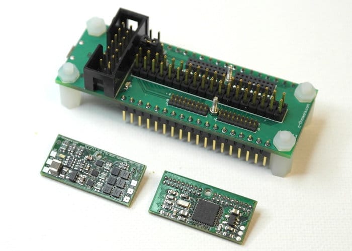
The open source sensorless BLDC motor controller offers a modular system that includes a Texas Instruments microcontroller MSP430FR5949.
The motor controller is now on Kickstarter with pledges starting from $19 for the processor module: shipping is expected to start during April 2018 and comes complete with open source firmware.
The modular design also allows you to independently control each module and use them in different systems. You can also change or update each module without affecting other connected modules, providing an easy way to expand and enhance your project as you go.
The system consists of three modules:
– Processor Module (PM) – MSP430FR5949
- 3…24V input voltage, 3.3V output, 150 mA LDO
- MSP430FR5949 microcontroller
- 768 kHz crystal
- pads for JTAG and UART interfaces
- all 33 (from 40) usable PINs are available
- small size: 1″ x 0.5″
– Application Module (AM), offering the analog part of BLDC motor controller
- 3…8.4V and up to 6A (12A MOSFETs)
- Current Sense Amplifier with gain 50
- Current Sense Resistor – 1/4 watt, 0.01 ohms, 1%
- power pads
- remote speed control pads (for 1…2 ms PPM, 0…100% duty cycle)
- small size: 1″ x 0.5″
– Debug Module (DM)
- 2-pin input power connector (up to 8.4 V)
- 3-pin jumper block for “external/JTAG” power
- 14-pin TI JTAG connector
- 2 x 18 pins 0.100″ pitch debug connector
- two 2 x 18 pins 0.050″ pitch sockets for PM
- two 2 x 18 pins 0.050″ pitch connectors for AM
- two 1.4 mm screws used for PM and AM aligned connection to DM
- green LED
- Micro USB Type B Connector and serial UART to USB IC
- two 18 pins 0.100″ pitch debug connectors for breadboard
- small size: 2.8″ x 1″
To learn more about it, watch the demonstration video below.


