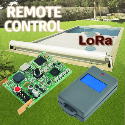
Palmtop transmitter to couple with the LoRa Shield to execute longer-range radio commands.
Among the longer distance radio transmission technologies with low energy consumption, there was one in particular on which we have focused our attention, it is the one LoRa (Long Range) produced by Semtech (www.semtech.com) with a product based on it, some time ago (issues #199, 200 and 201) we have designed and introduced a shield for Arduino capable of equipping the board with the LoRa technology. However, the project at the time was based on the SX1278 integrated circuit by Semtech (or the equivalent RFM98) which can be used in various ways:
- as narrowband transceiver for standard data transmission with amplitude modulation (OOK);
- as a classic data transceiver with frequency modulation (FSK), still narrowband;
- as LoRa transceiver, i.e. with “Spread Spectrum” technology.
The radio module we employed (SX1278) is the version with base frequency that can be set up to 525 MHz (typically aimed to be used at 433÷434 MHz) while the one used, for instance, in the network LoraWAN (e.g. SX1276) works at 868 MHz. in the first article we have verified the circuit’s flexibility, by using it as transmitter in OOK mode to pilot radio-controlled sockets produced by Avidsen or Velleman. In the two next issues, we have described its use as LoRa transceiver. For more information, you can see the documents found on the web at the addresses ww.semtech.com/images/datasheet/sx1276_77_78_79.pdf and www.hoperf.com/upload/rf/RFM95_96_97_98W.pdf.
In this article, besides describing the transmitter for LoRa remote control, we are going to recall some concepts regarding “Spread Spectrum” transition and in particular regarding the LoRa technique, for those of you who might have missed the previous articles or maybe you want to just go over the essential info one more time. In fact, the transmitter we have used, better described by the circuit diagram here beside, is designed to integrate with LoRa shield for Arduino and uses the same transmission characteristics; the shield becomes the receiving unit.
LoRa (Long Range) is a technology aimed to the IoT (Internet of Things), whenever exists in existing radio links such as WiFi and Bluetooth are not adequate. In fact, in order to bring data communication down to the level of mini/micro apparatuses with extremely low power consumption (for instance self-powered devices using batteries or solar panels), we need to use different radio transmission techniques than Wi-Fi (which is power-hungry) or Bluetooth (which has limited range).

Longer-range solutions proposed as of today are two:
- Ultra Narrow Band (UNB), which is transmission on a very narrowband in which you can concentrate the limited power of the (SigFox);
- Wide Band with Spread Spectrum, that is transmission where the information is spread over a wide spectrum of frequencies using dedicated algorithms; this way, data can be reconstructed even if a signal is very low or even below the noise’s threshold. LoRa proposal.
In both cases, the price to pay is the low transmission speed (some hundreds of bps, i.e. some tens of bytes per second). However, this limitation is not very important, since usually, IoT applications such as smart sensors only need the exchange of few periodical data between Peripherals and a data gathering and routing center on the Internet. What’s more important is that we are able to contact numerous mini/micro peripherals spread over the radius of a few kilometers, and these apparatuses must have a very low power consumption.
Spread Spectrum and LoRa
Spreading the data signal over a wide spectrum of the carrier wave can be done in two ways:
- a) by making the carrier wave hop from one channel to the adjacent one using a prefixed algorithm; this is what’s known as Frequency Hopping (FH);
- b) by matching each data bit to a string with many modulating bits based on a prefixed pattern (for instance pseudorandom); the receiver will then proceed to reconstruct the single bits by applying the inverted process.
It is possible to apply both techniques simultaneously, such is the case in LoRa. However, LoRa actually uses the technique described in point B.
this technique can be implemented using a digital super modulation, such as the case for DSSS (Direct Sequence Spread Spectrum), or by using other methods like those used in LoRa. In order to simplify the hardware, especially in terms of reception, LoRa doesn’t use DSSS but a sequencing of “chirps”; that is an oscillation which frequency varies linearly over time.

These allow for a simpler coupling of receiver and transmitter, as opposed to the DSSS, which needs precise timers. The data bytes are divided in nibbles (4 bit) to which 1 or 2 or 3 or 4 bits are added for controlling parity. The parameter defining strength on the transmission is CR, which can have in fact a value from 1 to 4. Therefore, if CR=4, it means that the data length of the payload (data to be transmitted) will be doubled, however, the safety of integrity is very high. In the time unit, as many chips are produced by the modulator (modulation unity) as there are Hertz in the bandwidth (BW) (LoRa project data). Therefore the chip ratio is Rc=BW. However, on each chip you can module 2SF values (symbols), where SF is parameter defining the “spread factor” which value can range from 62 12.
Therefore, the symbols ratio is Rs=Rc/2SF. Since there are 2SF values represented by SF bits, we can see that the bits ratio (bps) is Rb=SF * Rs. but we still haven’t considered the majority of the bits due to redundancy for the parity control defined by the CR parameter. This produces a surplus equal to the ratio (4+CR)/4 of the bits to be transmitted. Therefore, the transmission ratio as bps is ultimately bound to parameters BW, SF, and the CR through the following formula:
![]()
Therefore, the frequency of bits per second is directly proportional to BW and inversely proportional to SF (Rb ∝ 1/2(SF-1)).
Besides the bps, you also have to take into consideration the reception sensitivity which is directly proportional to SF and inversely proportional to BW.
Therefore, maximum sensitivity can be obtained with maximum SF and minimum BW. However, in this case, we also have a too low bps, therefore we have to find a compromise using a bigger BW in order to increase bit rate, especially if there are speed requirements to meet.
Table 1 shows the bps values for different values of BW and SF provided we use maximum redundancy (CR=4). Table 2 shows estimated reception sensitivity.
table1

Basically, the values of the most useful parameters in typical situations are: SF = 11/12 and BW = 4 – 9. Corresponding to values from 46 bps at -144 dBm sensitivity to 1.343 bps at -129 dBm sensitivity. In case of low bit-rates <1.000 bps), we have to refresh a module registry by enabling the flag for optimizing slow reception. It’s bit 3 of registry 0x26 (that replaces 1); you can do that by using the library function “SX.setLoraLowDataRateOptimize (boolean on)”; but this is on automatically by the library at initialization.
table2

Our remote control
The purpose of the articles appeared in the magazine for introducing the shield was to show the complexity and flexibility of the radio module SX1278 also in case of use with other types of modulations.
However, in this article, we will focus on using it under the LoRa protocol. For LoRa, the “LoRa Alliance” also developed a complex network protocol called LoRaWAN.
The Association also takes charge of certifying programs compatible with this protocol.

In the in-depth box on LoraWAN in this pages, you will find the main characteristics of the LoRa network.
Because LoRaWAN’s characteristics are complex and don’t really match with an amateur or semi-professional activity, we thought to provide a library for using the radio module and for implementing a bidirectional, multi-point LoRa communication.
So, we left to the user the task to build their own network according to their necessities, without the restrictions of a certified industrial protocol.
Using the library, you can easily manage two communicating stations, or a data gathering center and a multitude of widespread sensors, or other types of more complicated network structures. The library has been updated (version 1.2) by adding some additional feature (see ReleaseNote file). A library can be downloaded from the webpage https://github.com/open-electronics/LoRa.
The library can be used with basic functions with no routing, by wirelessly sending out a proper payload to check coverage. We can find an example in the sketches “LoRaTxEcho” and “LoRaRxEcho” in the attached examples. In this case, we see the fundamental features:
- library inclusion
#include <LoRa.h>
- class instance
LORA LR;
- initialization LR.begin();
- setting main parameters
LR.setConfig(SF,BW,CR);
//typically 12,7,4;
- sending the message
LR.sendMess(tbuffer);
- setting into reception
LR.receiveMessMode();
- receiving the message (loop n times)
if (LR.dataRead(rbuffer,maxlength) >0 ) break;
However, the library is organized with more sophisticated features in order to define and use the apparatus addresses. In particular, we can define the address of an apparatus within an identified network from a general address. Which means, we can use an addressing like:
network address – local address (of the device)
the dimension of network addressing is tied to the dimension of the local addressing. In fact, the overall address defined by the library is always based on 60 bits (unsigned integer for Arduino). Therefore, if for instance we decide to have an addressable space of 8 =256 devices, we have 2(16-8=16)=256 remaining possible values for the network.
Actually, the dimension of the local address is one unit lower, because address 0 identifies a broadcast transmission (so towards all the locals). In order to define this subdivision, we use the function:
LR.defDevRange(cod);
Where “cod” is equal to the exponent of 2; for instance 3 for range 1-7.
The function returns the max number of network addresses for a possible control.
Here’s some examples:
Code 3 : local address 1-7
network addresses 0 – 8191;
Code 4 : local address 1-15
network addresses 0 – 4095;
Code 5 : local address 1-31
network addresses 0 – 2047;
Code 6 : local address 1-63
network addresses 0 – 1023;
Code 7 : local address 1-127 network addresses 0 – 511;
Code 13 : local address 1-8191
network addresses 0 – 7.
Now, all we have to do is deciding the network address that must be within the limit established by the previous division.

These can be done using the function:
LR.defNetAddress(addr);
Which returns an error if “addr” is not within the limits.
Since the radio ranges are consistent, we have to protect the information; it is not a case that the LoRaWAN protocol provides a AES128 cryptography.
Even the library we propose implements an AES cryptography (although not AES256).
It is therefore necessary to establish an identical key between the apparatuses.
This can be done using the same initialization function, passing an integer as a key:
LR.begin(key);
Since the AES key is formed by 32 bytes, the “key” number actually serves as “seed” to initialize the random number generator; the same function then takes care of generating the 32 byte key. This way, we can exchange a simple number as communication key.
It is true only when you use the Arduino compiler for all the devices. In fact, starting from the “seed” the compiler’s routine will produce the same pseudorandom sequence for all the Arduino devices.
The main features to use in a proprietary LoRa network can therefore listed as such:
- library inclusion:
#include <LoRa.h>
- class instance:
LORA LR;
- initialization:
LR.begin(key);
- setting of main parameters:
LR.setConfig(SF,BW,CR);
//tipicamente 12,7,4
- definition of local address range:
LR.defDevRange(cod);
- definition of network address:
LR.defNetAddress(address);
- sending the message:
LR.sendNetMess(local receiver, local sender, message,lung);
- entering reception mode:
LR.receiveMessMode();
- receiving the message
(loop n times):
if (LR.receiveNetMess(dest. locale,mitt. locale, buffer, maxlung)>0) break;
- text extraction and decode:
LR.getMessage();
- extracts and decodes the sender address:
LR.getSender();
The reception function returns 0 if no messages arrived or no messages sent to the receiver arrived. Besides, it returns -1 if the message hasn’t been sent by the indicated center. If, in the message, the receiver has value 0, the message is always accepted (broadcasting). If the sender parameter of the function has value 0, messages are accepted regardless of the center.
Between the samples included in the library, you will find two sketches “LoraTxAddressing” and “LoraRxAddressing” which create a server communicating with several peripheral modules.
However, keep in mind that direct management of registers of the SX1278 can always be carried out from the base functions SX of the library.

Remote control and library
As we will see later in detail, the remote control uses the same LoRa module of the shields. Therefore, the same functions apply to the sketch acting on the remote control.
The remote contains an Arduino compatible as processor and clock speed with version “LilyPad with USB”. However, the remote sends out always the same message when the key is pressed. As a result, the transmission is always identical (although encrypted).
Anyone, if equipped with the right equipment, could record and repeat the transmission without the need for decoding. It is a problem of all remote actuators.
A problem we try to solve, for instance, by making the transmission always different using the “rolling code” technique. In order to solve this problem, in the library, we have provided a “marker”, which is a byte with a random value. The marker of the received message can be read and compared with the last marker arrived. In case that is present in this list, the message would be refused as suspect.
Dimensione of the list can be decided at will. Not too long in order to not have too high of a probability to find an already used marker.
Nor too short in order to control a sufficient number of already made transmissions. As we will see later, the remote turns on anytime the command key are pressed.
In this situation, we cannot use the random generator of Arduino which would be initialized every time with the same value.
In order to have a random value with each start, we must make use of electronic noise. In fact, we can read the value of one or more analog ports of Arduino, unused ports and left at high impedance. This value can be used as “seed” to initialize the random generator (or better yet, pseudorandom). To read to marker, we use the function:
LR.getMarker();
Keep in mind that the message is overall encrypted, except for the receiver. Therefore, even due to the operational mode of AES cryptography, the content, marker included, is distributed as noise over all the length of the message, making the safety really efficient.
Radio range tests
On the web, there are many radio range data, some more exaggerated and some other more realistic. A lot depends on the field, which can be more or less open, more or less difficult, and also depends on the position and the antenna.
Anyway, we can’t really talk about a few kilometers in an urban environment and 10 or more in open field. Data refers to LoRaWAN conditions where transmissions take place at 868 MHz. Therefore, we wanted to make some effective measurement in order to report some real data using our module at 433 MHz with a ¼ wavelength antenna.
Measurements have been done using the LoRa Shield for Arduino which has the antenna on the SMA connector. For the remote, which has a wire internal antenna, ranges are of course lower. Anyway, it has no problems reaching over four floors and an underground parking lot.
Back to shield with antenna, we have carried out two series of tests, one by placing the transmitter inside the house and one with the transmitter outside, on a balcony.
Transmission data are the following: SF=12, BW=5, power 10 dBm and 20 dBm. The other receiving shields were inside a car.
As you can see from the figure, with shields inside the house, the range is asymmetrical because the longest range is towards the window directly in front of the transmitter. Anyway, we can reach ranges of around 1 km.

In the figure, the range is not only symmetrical but also much bigger, at around a few kilometers. This test has been carried out, as nation, using a ¼ wavelength small antenna; by using a more efficient antenna, for instance, a 70 cm full-length one, and place in its unit elevated and unencumbered position, we suppose you could reach a few kilometers in urban environments and a few tens of kilometers in the countryside. Report measurements must be construed as approximate although based on a real environment.

LoRa remote
The LoRa remote includes both the Arduino microprocessor and radio module. Everything has been miniaturized in order to be inserted in the case of a classic pocket-sized remote for a keyholder. Due to the dimension and to unify voltages (in fact, the SX1278 works at 3.3 V), we have selected the Atmega32u4 processor with 8 MHz quartz, the same of the LilyPad with USB. The 8 MHz quartz instead of the 60 MHz the one as Arduino standard is a necessity due to the lower 3.3 V voltage. Anyway, since it is the same configuration of LilyPad with USB, we can (and must) select this platform from the programming IDE list. Of course, as the aficionados of Arduino programming might already know, programming keeps the same characteristics of “Arduino Uno”, since the IDE is tasked with monitoring the different clock speed during compiling. For the programming, we have provided a micro USB port on the remote.
In the figure, you can see the block diagram. As you can notice, the transmitter is powered when the command key is pressed; this means that a processor must be quick to intervene on the electronic switch, in order to maintain power when the key is released. In fact, this is the first thing it does, with no problems considering the human intervention times which are a few tens of milliseconds. The processor uses D6 pin to ground the gate of the Q1 (p-channel) POWERMOS through the T1 transistor. T1 transistor works in parallel to the key, therefore, keeps the Q1 POWERMOS in conduction even when the key is released. Once it stabilizes the power, the processor initializes the radio module with the LoRa characteristics defined by the sketch and using the network and local addresses. Besides, it initializes the pseudorandom number generator of Arduino’s C compiler, with a couple of values read from the unused analog pins (A0 and A1) and multiplied between them. This way, it uses variable electronic noise with each start. This is necessary in order to produce a casual marker for the message. Now, it sends out a message using the established pattern and waits for an answer. When it receives a positive response, it signals the execution using an agreed bip code, through the buzzer. Otherwise, after a certain waiting period (a few seconds) or after receiving a negative response it signals a different bip cold. Then it turns off, i.e. it brings D6 pin to logical low. List 1 shows the sketch prepared as an example for the LoRa remote.

This way, both the processor and the radio module are powered only for a few seconds (with an average consumption of around 20 mA during activity). A simple A23 battery is therefore enough to make it work for a long time. The server receiving in handling the command can be implemented as reported in the sample sketch included in the library. Essentially, all it has to do is listen and wait for the transmission from the remote control, verify the agreed pattern and verify that the marker is not present in the list of those already arrived. In case of a duplicate, it discards the message and responds negatively. On the other hand, in case the marker is original, it is inserted in a random position on the list and it sends out the confirmation after carrying out the action. Marker insertion in the list in a random position, by overriding the one possibly already present, is done in order to avoid any kind of periodicity.
List1
LORA LR; //instance of the class (for other global parameters used, see the complete code)
void setup()
{
pinMode(pinon,OUTPUT); // activate the MOS to keep the power supply
digitalWrite(pinon,1);
digitalWrite(pinf,1); // set up the buzzer
digitalWrite(psound,1);
if (!LR.begin(KEY)) {sketchend(1);return;} // initialize the radio module and the cryptographic key
LR.defDevRange(RANGECODE); // initialize the network and transmission parameters
LR.defNetAddress(NETADD);
LR.setFrequency(FREQ);
LR.setPower(PWR);
LR.setConfig(SF,BW,CR);
int seed=analogRead(0)*analogRead(1); // initialize the random generator with electr. noise.
randomSeed(seed);
sendCommand(); // spedisce il comando
if (!getCommandReply()) {sketchend(2);return;} // if the answer is OK warns with a beep signal
//otherwise warn with a different beep signal
sketchend(0); // it turns off automatically
}
void loop() // not used
{}
Naturally, there is always the possibility to receive a message with a marker already present in the list although original. However, since transmission is bidirectional, the server signals the no activation and you can simply repeat the command.
Practical creation
Alright, now let’s talk a bit about how to build the TX; we already took care of the shield in the corresponding article.
All the components of the transmitting unit are in SMD, except for the double pin-strip and the key and they are placed on a double-sided printed circuit, which tracks can be downloaded from our website along with the other files for the project. For the assembly, you must have a soldering iron no more powerful than 20 W, with a very fine tip, besides soldering wire with a 0.5 mm diameter, a small pair of pliers to place components and flux gel to help adhesion of soldering alloy. A magnifier will help centering the smallest components inside the respective pads and to identify, once all the soldering is done, possible shortcircuits caused by an excess of soldering alloy on adjacent terminals.
Components must be placed following the mountain scheme you can find in these pages, where you can see the right orientation of the polarized components. All the elements, including pin-strip and key, must be mounted on the top side.
The remote has been designed to be inserted in the remote box 5100-SPL10120 with diamond actions 61 x 37 x 15 mm with a battery box for a 23A battery and a button cover that perfectly overlaps P1 key (P2 key, the RESET, must not be taught when activating to remote from the outside). The transmitting unit, after assembly, is ready to be used, since it does not require any calibration.
Alternative use for the remote’s hardware
If we connect a dry contact in parallel to the key, e.g. a reed contact like those used for windows and doors (those used for antitheft systems, E.N.), we will create an efficient wireless sensor for an antitheft system. For instance, by connecting it to a door we will be able to receive on the server, even a distant one, a notification when the door is opened that would be used as an alarm or to register an event. In fact, we remind you that the LoRa Shield can be mounted on RandA (our shield for Raspberry Pi which integrates the core of Arduino UNO) where the Raspberry Pi processor can act as a sophisticated server, possibly connected to the Internet.
The miniaturization of the remote control and its autonomous power make it fit to be placed anywhere we need to have a mechanically activated sensor. If we add a small circuit for making a low consumption timer (a few nanoamps), we could electronically activate the key, for instance using a MOS transistor acting like a switch. In this case, we could periodically send the server an analog value coming from A2 pin or a digital value from D8 pin.
For this alternative use, we could use a container comparable in terms of size to a G1013 (with some adaptations), in case you don’t want the small key window.
These alternative uses of the remote control take advantage of the momentary activation of the circuit which power is provided by a small, non-rechargeable battery. We are already working on designing a further enhancement of the remote circuit. In this new board, which size is not that different from the remote, we will add a battery charger for 3.7 V LiPo batteries. The result will be a board with processor and radio module with the possibility to be self powered and stay always on. This way, the system can listen for incoming messages or create its own based on various alarms. In fact, the analog and digital pins available on the micro board will be increased.
Basically, we have a group of three types of devices:
- shield for Arduino (and therefore also for RandA) already introduced and aimed for servers or more elaborated stations;
- micro-board with possibility of self-powering through the rechargeable battery, including an Arduino processor (type LilyPad) and radio module; aimed to peripheral stations, also powered by solar panels.
- Remote/mechanical alarm, introduced in this article.

Conclusions
Thanks to the miniaturized LoRa transmitter and with the next self-powered ones, we complete the offer of programmable systems that can create a proprietary network for countless different uses. The use of the library proposed in this article makes these networks very flexible and far from the complex rigidity of LoRaWAN. LoRaWAN was born to standardize IoT from an industrial perspective. It is designed to bring to the Internet these information exchanges involving numerous sensor satellites and actuators within a very encoded Logix (see in-depth the box). Since we don’t want to get into this more complex reality, where it would be more fitting to use an 868 MHz module, it would, however, be a shame not to make use of the great potential of this wonderful regional module.
Using these apparatuses and this library, we can create different customized solutions. For instance:
- a sophisticated car antitheft system with alarm on the same control;
- a sophisticated alarm system extended to houses or businesses;
- a management solution for sensors and electro-valves for the farming industry;
- automation of apartments and villas on a vast scale;
- surveillance for critical environmental values.
There are also other applications of the system, which would be to time-consuming to list so we refer to leave them to your imagination.
From openstore
LoRa radio control – mounted
Lora shield for Arduino – Mounted

[…] are opened. To put it together, we have used the LoRa radio control hardware already shown in the previous post, composed of a transmitter board (Fig. 1) that is triggered when a key is pressed or when the […]