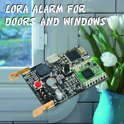
Let’s create an alarm to be notified when doors and windows are open, even from a notable distance, using a modified LoRa TX palmtop.
Long-range radiofrequency data communication technology, also known as LoRa, is employed in several fields, from IoT (elective use) to automation, to applications that were based on traditional transceivers.
The versatility in terms of fields of applications has been also shown in the many articles dedicated to the LoRa technology, the latest of which, perfectly fitting the summertime, was the one dedicated to Safety Sea, an alarm system for boats which notifies when people in the water swim too far away.
After this interesting project, published in the issue from last June, we want to propose a new “civil” application for 433 MHz LoRa modules: it is an alarm system that is triggered when doors or windows are opened. To put it together, we have used the LoRa radio control hardware already shown in the previous post, composed of a transmitter board (Fig. 1) that is triggered when a key is pressed or when the correspondent line is grounded.

Fig. 1
The possibility to add the transmission key contacts on the PCB allow us to control the transmitter via an external device, which may be a switch or a circuit with clean terminal output or transistor output; we can have one just by “bringing out” the key’s contacts using wires and identifying the ground wire, in order to find the “hot one” which also must be grounded to start transmission. In order to better explain this concept, we are publishing, in Fig. 2, the block diagram of the radio control’s transmitter, where you can easily see how the keys are connected and therefore how to insert an external trigger and switch.
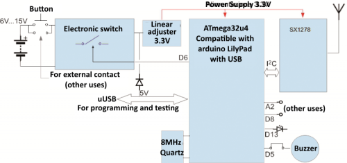
Fig. 2
Normally, the transmitter doesn’t absorb power because it is off (it is turned on and activated by bringing to ground the control inputs or pressing the corresponding keys): so it can be easily powered by a battery, therefore granting long replacement intervals. To this regard, we must mention that there is a 12 V, A23 battery inside the FT1250 transmitter, however we have chosen this one only due to the very restricted space imposed by the TX dimensions; the A23 can’t support more than 300÷400 activations, so we decided to use something more capable for our transmitter. Of course, this means we had to choose a bigger container capable of hosting a much bigger battery than the series of button cells composing the A23.
Applying a different battery is not a problem, because the power required by the transmitter board can range from around 4 to 15 Vcc since there is a linear voltage regulator inside the circuit extracting the stabilized 3,3V needed to make the electronics work.
In order to use the LoRa palmtop transmitter as door opening sensor, we can consider applying a magnetic switch; the latter is actually composed of a deviator and a magnet. The deviator has a normally open contact (NO) and a normally closed contact (NC). The NO is closed by the proximity of the magnet and vice versa for the NC (Fig. 3).

Fig. 3
In order to apply this magnetic contact to the radio control board, we must keep in mind that it is impulsively activated by a key, while the magnetic contact is a persistent type of triggering. This is why we have to turn the magnetic contact activation into an impulse and we can do this by using a small adapter circuit as shown in Fig. 4. The alarm is triggered when the magnet, placed on the door, moves away from the magnetic contact, therefore, in normal position, the contact charges up a capacitor that is discharged on the base of a transistor when the door is opened, therefore the key is to short-circuit for some tens of milliseconds, enough time for the ATmega32U4 to intervene and pilot the transistor that keeps the power up.

Fig. 4
For the application described, apart from the circuit integration, the firmware uploaded to the ATmega32U4 of the transmitter is identical to the LoRa radio control’s original one, which means that, upon activation, it instantly activates the transistor that keeps the power-up, sends out the alarm message and deactivates the transistor by turning the board off; in fact, our additional hardware supports the TX’s native functioning.
You then have the possibility to implement the functions you want on the unit you are going to use: in the simplest case, you can couple the transmitter equipped with a magnetic contact to a LoRa receiver, but if you want something more, you can create a server that will receive the alarm message from a transmitting unit or the alarm signals of more TXs. The server will be able to record the event, activate an alarm or send out an email or an SMS message is based on a RandA hardware (i.e. Raspberry Pi).
Compared to a classic wireless alarm for home and internal use, keep in mind that LoRa transmission allows to reach noticeable distances, therefore you will have to write a specific firmware based on Arduino that takes advantage of the specific LoRa library which will be able to handle numerous nodes and therefore a consistent number of points to be monitored.
Practical creation
With that said, let’s see how to put together the transmitter and use it to create a wireless LoRa sensor for doors and windows: first thing to do is get your hands on a FT1250 LoRa transmitter to mount (you can find it on Open Electronics, also on the online store ) and get rid of the container, keeping only the printed board. In doing that, you have to identify the pads corresponding to the keys contacts and connect them following the circuit shown in Fig. 4.
In order to identify the keys pads, you can use Fig. 5 as reference, where the PCB is shown from the solders side PCB indicated by the arrows (the bottom contacts correspond to the top ones); in the aforementioned picture, GND is the ground context of the key while P is the hot terminal, the one piloting the circuit and corresponding to the collector of Q1 transistor from the diagram shown in Fig. 4.
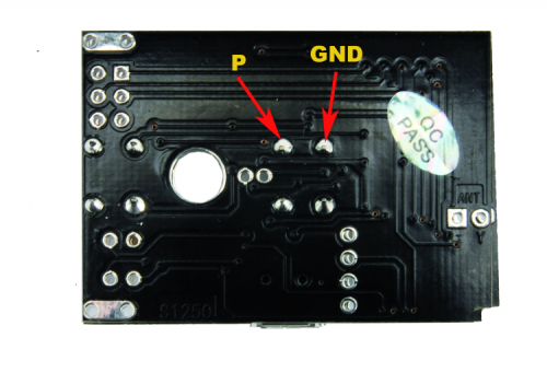
Fig. 5
After connecting two wires to the keys contacts to bring them to the transistor, the printed circuit of the FT1250 LoRa transmitter must be equipped with two power wires (we suggest red for the positive and black for the negative or GND…) to connect to the positive and negative pad reserved for the spring contacts for the original battery (which is not to be installed) provided and used to power the transmitter with the battery of choice. The whole thing must be placed in a new adequately-sized container, on which you’re going to place the reed contact on one side, which is the magnetic control deviator of the contact for doors and windows, as shown in Fig. 6.

Fig. 6
Installation
The container used in our prototype is made of plastic and its dimensions are 130 x 70 x 28 mm, therefore, although bigger than the TX’s original one, is still small enough to be easily placed on the doorframe. For fixing it in place, you will notice that the magnet already has two eyelets for two screws, while the electronic unit can be applied using strong double-sided tape or with a pair of plastic brackets or mounts, also using small screws (smaller screws in order to avoid damaging door or window frame where you are going to place the LoRa system). As for the power, we are using 4 rechargeable AAA Ni-MH batteries (for a total of 4.8 V) or 4 AAA non-rechargeable lithium batteries (for a total of 6 V), which will guarantee some thousands of events, meaning that, based on average use, we have at least a one-year duration.
In fact, each transmission after the magnet moves away from the reed deviator absorbs around 85 mA (at 5÷6V) for around 300 ms, therefore it is reasonable to suppose around the year of duration, considering that opening and closing are not continuous. The power consumption reported has been calculated considering that the LoRa RTX transmitting unit operates at a fixed power of 10 dBm (1 0mW), although it can range from 70 mA to 150 mA by decreasing or increasing the power itself.

Fig.6b
Programming
The sketch to upload to the transmitter (called allarmeporta.ino) is shown in List 1. It is understood that the program and will require to connect the board to your Personal Computer using a micro USB cable, fitting the existing connection on the TX board (in fact, the FT1250 has a micro USB connector on its PCB site). We remind you that the radio control hardware is based on an Atmega32u4 MCU (just like Leonardo, the only difference being that this microcontroller’s clock is 8 MHz), therefore, for its programming, we must select the USB Lilypad board from Arduino’s IDE, since it uses the same CPU and clock configuration.
Listing1
#Includes "LoraNode.h" //Includes the Lora library
LoraNode Node(2); //Knot room with address 2
#define pinon 6 // pin that keeps the board on
#define psound 5 // pin for buzzer
#define pinf 13 // pin for the signaling led (not used)
#define eventHandler 1 //Address of the server node to send the alarm to
void setup() {
pinMode(pinon,OUTPUT);
digitalWrite(pinon,1); // keep the card on
pinMode(pinf,OUTPUT);
pinMode(psound,OUTPUT);
digitalWrite(psound,1); // buzzer off (reverse logic)
// Serial.begin(9600); while(!Serial){ delay(10);}; // debugging only
// Serial.println ("Pin ON!"); // "
sendEvent(); //Hears the alarm
sketchend(); //Off all
}
void loop() { // not used
}
void sendEvent()
{
// Serial.println("Sending alarm"); // Only for debugging
Node.writeMessage(eventHandler, "DoorOpen",500); //sends message
// Serial.println("Alarm sent"); // only for debugging
bsound(); // comment if you want to be silent
}
void sketchend()
{
digitalWrite(pinon,0); // switch off the power supply
}
void bsound() //sound echo (buzzer)
{
digitalWrite(psound,0);
delay(100);
digitalWrite(psound,1);
}
Given the generous coverage offered by the LoRa protocol, the alarm can be placed even at great distance from the controller and can be replicated on different openings (doors, windows, shutters etc.); considering that, in this case, we might have an overlapping of messages generated by more units, the library will have to wait for a certain time (500 ms in the example sketch) to check for absence of radio traffic and will be there for capable of overcoming, within certain limits, the bandwidth crowding caused by multiple alarms.
From openstore
RandA – Raspberry Pi and Arduino board
