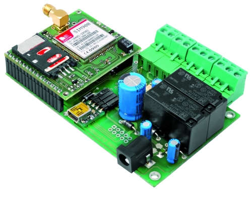
Now that we have seen the electric scheme, we can work on the practical aspect of the project; let us state in advance that its making presupposes a double-faced printed board with metallic holes, using many SMD components, all this in order to reduce the overall size of the device.

Top Layer

Bottom Layer
PARTS LIST:
R1: 0,1 ohm 1W (1206)
R2, R21: 2,2 kohm (0805)
R3: 1,2 kohm (0805)
R5, R6, R9, R11: 4,7 kohm (0805)
R7, R8, R13, R14, R17: 330 ohm (0805)
R10, R12: 10 kohm (0805)
R12: 10 kohm (0805)
R15, R16: 1,5 kohm (0805)
R20: 1 kohm (0805)
R4, R18, R19, R22, R23, R24, R25, R26, R27: unused
C1, C4, C7, C13: 100 nF multilayer (0805)
C2: 1000 µF 35 VL electrolytic
C3: 100 pF ceramic (0805)
C5: 100 µF 16 VL electrolytic
C11, C12: 100 µF 16 VL electrolytic
C8, C14, C15, C16: 470 µF 6,3 VL tantalum (CASE-D)
C6, C9, C10, C17, C18, C19, C20: unused
Q1, Q2: unused
U1: MC34063AD
U3: 24FC256-SN
U4, U5: TLP181
U6: PIC18F46K20-I/PT (MF857)
U2, U7: unused
D1, D3, D4: 1N4007
D2: 1N5819
T1, T2: BC817
LD1, LD2: LED 3 mm red
LD3, LD4: LED 3 mm yellow
LD5: LED 3 mm green
L1: Coil 20 µH
RL1, RL2: Relay 5V single pole
P1: unused
F1: Slow fuse 2 A (1206)
Miscellaneous:
– 2 pole terminal block (2 pcs.)
– 3 pole terminal block (2 pcs.)
– power plug
– 6 pin male strip
– 3 pin female strip
– 16 pin female strip
– 4 pin 90° female strip
– PCB
Download PCB details (Layout and Gerber): PCB
