
A new useful and intuitive Android app to easy manage our TDG133 GSM remote control.
In this blog we often use the SIM900 GSM module for remote control applications, like the TDG133 (2 IN / 2 OUT) , TDG134 (Gate opener), TDG139 (Temperature control) and TDG140 (2 IN / 2 OUT with DTMF) remote controls. They are home automation devices that allow both to detect and notify alarms via SMS and to control remote devices as electric locks, irrigation systems, motorized gates via a simple text message or a GSM call. For these devices we have developed an Android app that will allow you controlling them and receiving their alerts through a graphical interface that will make everything so easy.
This app is called TDGRemote for TDG133, it is a free download from the Google store, and is written basing on the TDG133 remote control that manages 2 inputs and 2 outputs. The code is written in a modular way, so in case we want to manage other remote controls with more I/O lines we just have to make simple customizations, even because the additional commands are very similar and the application code is available online, then you can easily implement new functions at will.
The idea of developing an app was born because our remote controls are operated by sending text messages, which, having to be short, forces us to use a syntax that may appear cryptic and difficult to remember. Using the app you do not have to worry about storing and executing the right commands, but everything will be more intuitive through the graphical interface. To activate a remote control output, for example, just press the button not worrying about typing the correct command, because the application code will do the right matching.
At the same time this app will also perform a check on the strings to be sent so that they are syntactically correct: this avoids wasting a SMS for a wrong syntax string or for a typo. Even wrong settings values, i.e. outside the allowed thresholds, are warned by an error windows to avoid wrong device status.
PREPARING THE REMOTE
Before trying the app, let’s make sure that the SIM card is present in our remote and is not locked by the PIN number, or it will not respond to our messages.
Once powered the board, the green LED will flash every second during the connection to a GSM network, then it will change the flashing frequency (once every 3 seconds) to indicate normal operation. Now we can use our app, but it’s better to properly configure it before doing that.
Let’s look at the various App sections to explain how to manage our TDG133 remote; it is also useful as a various available commands quick review to make the best use of these remote devices.
SETUP SCREEN
Before looking at the main screen, you need a brief description of the configuration pages, where, after the first installation, we’ll need to set some fields. To access this screen just press Android Menu key and select the Settings icon; you will see a screen like the one shown in figure. Obviously we can access this screen any time to change some of these settings.

In the first box, Remote Device Name, we write our remote device name so it can be distinguished from any other in use.
Remote Number Sim will be the destination number, the SIM number housed in TDG133. To update immediately this field just press the button below (Set).
The box password should be changed if you want to change the remote control password and send it to the TDG pressing the Set button on the right: this will send the command to the device via SMS and then you will receive a message confirming the change. The default password is 12345.
Also in the password box, the Request always password checkbox forces or not the user to type the password each time before sending a command message, increasing the application safety and avoiding erroneous activations of some output.
Startup Message Box is used to set the initial message that the remote will send to our smartphone every time it is turned on: this feature can be disabled by unchecking the Use Startup Message; pressing the Set button below will send the command message.
The Forward no-std sms box sets which phone number to route not standard syntax messages that are received from the remote: these are not SMS command but, for example, alerts the mobile operator sends on remaining credit. This phone number will be chosen (through a combo box) among a numbers list (stored in the remote control memory) that is also managed by our app through a screen (WhiteList) that we will see later. The two buttons below are used to request the list update (Request Update) and send the information to the remote control (Set) as SMS messages.
The Option Misc. box has two checkboxes that do not require SMS commands sending, but are internal use options; in particular, Disable Multi Answer prevents the remote to answer to broadcasting SMS, while ticking the option Confirm before send message will show you a confirmation dialogue box before any command sending; This will prevent sending wrong or unnecessary commands, saving your money.
Get Signal Quality box has a button to request the remote control antenna signal quality (always requires sending an SMS message); after receiving the message, the information is reported as a progress bar with a timestamp of the last request made.
The Factory Reset button will send a command to bring our remote control back to the original settings.
Finally the Version box allows you to view, after receiving the response message, the remote control firmware name and version. In figure it is TDG133 V 2.8.
The button to save all settings and return to the main screen closes this screen and opens the main screen.
MAIN SCREEN
From the main screen in follow figure we can monitor the IN1 and IN2 inputs status (top area) by the round LEDs color and that of OUT1 and OUT2 outputs (at the bottom) using the corresponding buttons. In particular, the LED will be green when the respective input is active and will be gray in case of inactivity. About outputs, the on or off labels over the buttons will indicate the current remote control relays status.

Since after the first installation we can’t know what is the remote control current state, you will need to send an update request command by pressing the string below the Update I/O State section: this will send a message our remote control will respond to with a string formatted in a particular way. The app will fetch it, updating so the controls status and the whole running configuration.
To verify the displayed information validity, you can see at the bottom the date and time of the last update.
CONFIGURATION INPUTS
Each input can be configured from the main page by pressing the button below the corresponding LED, you will see a screen. In it, the Alarm in level box will allow you to choose whether to activate the selected alarm on the level (high or low) or on the input signal change.

The box below, reset inhibition time, allows us to set a period of time following the event that caused the alarm, during which a further alarm will not be considered. This function can also be ignored (continuous reception of each alarm) by deactivating the corresponding checkbox.
The box Observation time pre-alarm lets you define a time interval in which the condition that triggers the alarm must remain valid. This would prevent the sending of false alarms due to electrical noise affecting the corresponding input.
Finally, the Enable alarm message lets you choose the message text we receive on the smartphone when the corresponding input will be high or low. In the same box you can define the maximum number of messages that will be sent, with the setting Max number of SMS-Alarms. The interval between sending an SMS and the next one will depend on the inhibition time defined previously.
With the Set button always present in any screen section, we will send a command message to set our choice. Also in this section we can request a status update by pressing the icon in the bottom left; We receive a special answer message showing the date and time of last update too.
OUTPUT CONFIGURATION
From the main screen, by pressing the icon or the output settings label we will enter the output configuration screen. This time we can configure OUT1 and OUT2 from the same screen shown in figure.

We can see that both outputs have two configuration possibilities, Normal and Toggle: with the first, each press of the corresponding button will activate or not the connected output. With the second mode, you can reverse the present status for a defined time (configurable in the box): it is, therefore, equivalent to generate a pulse (high or low) to set duration.
Furthermore, this type of setting does not need sending a command message.
As you can see from figure , on OUT1 output you can configure the gate opener mode. In this mode, you can associate to OUT1 button a phone call that activates the relay for a time interval set through the dedicated box. If you want a “bistable” working mode (without any activation interval, only open / close command) simply select the Toggle Mode. As for the gate opener mode, it will be necessary to send the command message via the Set button.
Please note that a maximum of 200 people can open/close a motorized gate by simply making a phone call to the remote control SIM number, without needing the app. The app is needed instead to configure the allowed people phone number list, that is stored on remote control internal memory.
Depending on the output configuration, the main screen will display proper writings to clarify the operating mode.
CONFIGURATION REPORT
By default this feature is not enabled, but the TDG remote can constantly monitor inputs and outputs status via a custom report, configurable in the Reports screen that is accessible from the main screen menu. This screen is displayed in figure, where we can see how to define the interval between messages (hours: minutes: seconds) and the message format (binary or text). Again, for making changes permanent you need to press Set, which will send the command message.

MANAGEMENT LISTS
On remote control internal memory you can store two special lists. The White List is up to 8 telephone numbers to be notified (with text messages or voice calls) when the alarm condition is triggered. Through this list, displayed in figure , you can decide by checking the appropriate SMS or CALL boxes, what to send to each single telephone number (SMS only, calls only, or both).
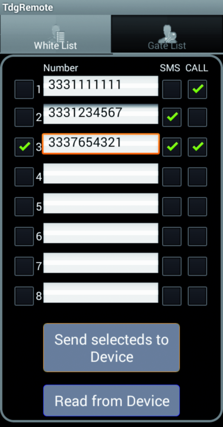
Also, numbers on this list have the ability to send commands to remote control without needing to enter passwords. This applies to phones without the installed app only because when using it, the password will be entered automatically.
Before adding a new number to this list you should run a remote control memory reading by pressing the button Read from Device, placed in the bottom of the screen: this will send a command message to get the current configuration.
At this point, by holding down for two seconds the finger on a blank text box, the smartphone phonebook will be open to select the desired phone number to be added to the list. Once completed, you can update the remote control internal memory by pressing the button Send selected to Device.
The TDG remote manages also the list of maximum 200 numbers able to trigger the gate opener by just calling the SIM number. To access this list, press the Android List menu button, then the Gate List tab (on the right of the White List one); You see an interface like the one shown in figure from which you can add a new number by using the Add button or delete one (or all) by selecting the appropriate checkboxes and by pressing Delete button.
CODE
After these features overview, we just limit to a brief analysis of the app code.
We will focus on some functions that allow you to manage the Android phone calls at run-time. In Listing 1, there are two methods defined in telephony.java class that allow, in a very simple way, to dial a call simToCall (callNumber) and to send a text message (sendMessage).
Listing1
public boolean callNumber(String simToCall)
{
try
{
Intent callIntent = new Intent(Intent.ACTION_CALL);
callIntent.setData(Uri.parse(“tel:” + simToCall));
callIntent.addFlags(Intent.FLAG_ACTIVITY_NEW_TASK);
_context.startActivity(callIntent);
return true;
}
catch (ActivityNotFoundException e)
{
Log.e(“GSM Call Example”, “Call failed”, e);
return false;
}
}
...
public boolean sendMessage(String message)
{
String messageInfo = “sending command to “ + _simToCall + “: “ + message;
Log.v(TAG, messageInfo);
Toast msg = Toast.makeText(_context, messageInfo, Toast.LENGTH_LONG);
msg.show();
if (!dbgMode)
{
SmsManager smsManager = SmsManager.getDefault();
smsManager.sendTextMessage(_simToCall, null, message, null, null);
}
return true;
}
Similarly, we can handle an incoming SMS and analyze it according to our needs, through the class IncomingSMS shown, although not completely, in Listing 2. It is a class that derives from BroadcastReceiver and with OnReceive () method gets, with simple code, the message body and the sender telephone number.
Listing2
public class IncomingSms extends BroadcastReceiver
{
public static final SmsManager sms = SmsManager.getDefault();
public boolean parseMessage(String message, String callingNumber)
{
...
return true;
}
public void onReceive(Context context, Intent intent)
{
final Bundle bundle = intent.getExtras();
try
{
if (bundle != null)
{
final Object[] pdusObj = (Object[]) bundle.get(“pdus”);
for (int i = 0; i < pdusObj.length; i++)
{
SmsMessage currentMessage = SmsMessage.createFromPdu((byte[]) pdusObj[i]);
String phoneNumber = currentMessage.getDisplayOriginatingAddress();
String remoteNumber = TdgRemoteActivity._remoteSimNumber;
String senderNum = phoneNumber;
String message = currentMessage.getDisplayMessageBody();
Log.i(“SmsReceiver”, “senderNum: “+ senderNum + “; message: “ + message);
parseMessage(message, senderNum);
}
}
}
catch (Exception e)
{
Log.e(“SmsReceiver”, “Exception smsReceiver” +e);
}
}
}
Of course we should not forget to add the right permissions in AndroidManifest.xml together with IncomingSms class registration on the receiver, as in Listing 3.
Listing3
<manifest>
<uses-permission android:name=”android.permission.SEND_SMS”></uses-permission>
<uses-permission android:name=”android.permission.CALL_PHONE”></uses-permission>
<uses-permission android:name=”android.permission.READ_CONTACTS”></uses-permission>
<uses-permission android:name=”android.permission.CALL_PHONE”></uses-permission>
<uses-permission android:name=”android.permission.RECEIVE_SMS”></uses-permission>
<uses-permission android:name=”android.permission.READ_SMS” />
<application
android:icon=”@drawable/ic_launcher”
android:label=”@string/app_name” >
<activity
android:label=”@string/app_name”
android:screenOrientation=”portrait”
android:name=”.TdgRemoteActivity” >
<intent-filter >
<action android:name=”android.intent.action.MAIN” />
<category android:name=”android.intent.category.LAUNCHER” />
</intent-filter>
</activity>
<receiver android:name=”.IncomingSms”>
<intent-filter android:priority=”1000”>
<action android:name=”android.provider.Telephony.SMS_RECEIVED” />
</intent-filter>
</receiver>
....
</application>
</manifest>
From openstore
TDG139 -> GSM temperature control
