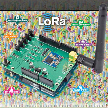
Let’s equip Arduino with a long-range communication module, and one based on Semtech technology.
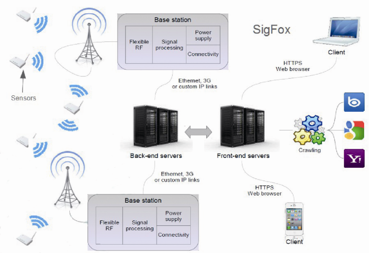
In this post we had the chance to talk about two technologies that compete for the market of the low-energy, long-range (few kilometers) wireless communication: that is, the SigFox and LoRa technologies. It is now the time to transfer the wireless long-range technology to the Arduino platform, and for this reason we propose a shield using a RTX LoRA module, and that is equipped with the corresponding software library, thus allowing an immediate usage.
Ultra Narrow Band
A possible solution is the one to restrict the modulation spectrum very much, so to reach some tens of Hertz: this can be achieved both by reducing the data-rate, and with some tricks concerning the modulation and filters.
In SigFox, the carrier wave’s frequency is 868 MHz in Europe, the modulation is GFSK and the data-rate is 100 bps, with a communication slot’s width of just 100 Hz; thus more terminals may be able to broadcast at the same time, by allocating the available slot. Since the spectrum is a very thin one, all the energy is concentrated, and as a consequence you only need little so that the signal has a width greater than the noise.
Spread Spectrum
An alternative is the one to distribute a signal (once again, one having a low rate) on a band being much greater than the needed one, by using some dispersion function. A reconstruction is carried out by means of an inverse function.
The dispersion function is generally a pseudorandom one, or a function causing some continuous frequency hopping or, finally, a combination of the two techniques. The result is a signal dispersion at a noise level, which makes interceptions and interferences difficult. Even in this case the energy needed is very limited, even though the spectrum is very wide, since it doesn’t matter if the signal is at the same level of the noise, given that the signal may be reconstructed by the processing.
This technique has been borrowed from the military sector, and in fact it creates a sort of “camouflage” through the air. In LoRa, the dispersion band may be fixed from 7.8 kHz and up to 500 kHz.
Moreover, each signal’s byte is modulated on several radio fragments (Spreading Factor). This amount may be defined, from 64 and up to 4,096.
Thus the effective rate may go from about 18 bps (minimal band, maximum spreading factor) and up to 78 kbps (maximum band, minimal spreading factor).
And even the sensitivity and the SNR value (signal/noise) are influenced by it; in particular, an increase in the spreading factor will increase the SNR value and the sensitivity, while an increase in the band will decrease the sensitivity. More specifically, as for the SNR, it goes from -5 dB up to -20 dB, while as for the sensitivity it goes from -124 dBm up to -134 dBm.

The Arduino shield
The shield we have prepared uses LoRa’s technology, and is based on a DRF1278F module by Dorji, which in turn is equipped with Semtech’s SX1278 chip, the heart of the system. The SX1278 is a very sophisticated and versatile component, that makes extensive use of the SDR, thus it can be completely configured.
The first thing to point out is that the SX1278 is not dedicated to the LoRa system only, but that it may transmit and receive even in the classic FSK or OOK modes. In these cases, the communication may be carried out by means of a packet protocol with NRZ encoding, or even with any other encoding, by directly sending (or receiving) the pulses via an I/O pin. In this last case, the chip operates as a simple transceiver.
The SX1278 is part of the SX12xx family and can be distinguished from its other members because of the carrier’s frequency range, that goes from 123 and up to 525 MHz; the other ones may even reach 1.020 MHz.
In this first part we will describe the shield’s structure, and its usage in the OOK or FSK modes, while in the second part we will deal with the communication in the LoRa mode.

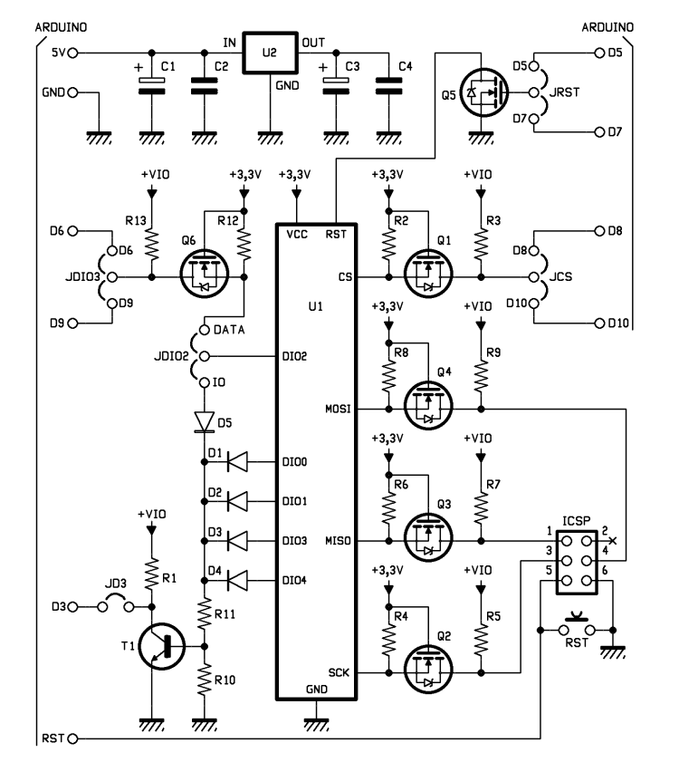
The board’s structure is quite a simple one since, in addition to containing the small DRF1278F board, it has a power supply reducer, from 5 to 3.3V, some level converters (because SX1278 operates at 3,3V) and a combination in OR logic, for a possible interrupt management that the SX1278 may create on its I/O pins. Moreover, some jumpers allow the choice and the enabling of the signals, via Arduino’s pins. As an example, the chip select (denied) may be connected to Arduino pins D8 and D10, while the SX1278’s reset may be connected to the D5 or D7 pins. The interrupts’ logical OR may be connected to the D3 pin, that is one of the two possible external interrupts in Arduino. But SX1278’s DIO2 may also be used as input/output for pulses (as we will see later), and can be connected to the D6 or D9 pins. Finally, the SPI bus, used in order to communicate with the SX1278, is connected to Arduino’s ICSP connector.
It has been needed to include a power supply reducer from 5 to 3.3V, since the absorption in the transmission stage (at the maximum power) may reach 120 mA, and Arduino’s 3.3V converter is not enough to guarantee the absorption.
It is appropriate to keep in mind that, while the SX1278 has two outputs for the antenna, the small DRF1278F board has only an external one: it is the one dedicated to the larger power range (“boost” output). This one turns out to be connected to the antenna connector, in SMA format. Consequently, in order to acquire the antenna signal, it is needed to enable this output (that in the default settings is not enabled) by means of the configuration of a SX1278’s registry (the 0x09 registry).

The SX1278’s configuration implies the update of its internal registries via the SPI bus. The configuration registries are an impressive number of 112, of which the greatest part manages several functions by means of bit groupings. Moreover, some have a different behaviour or, more accurately, they have more copies, depending on the mode: LoRa or FSK/OOK. In the case of data packets, they are sent to a FIFO (First In First Out) queue, via the SPI bus, and then extracted and serialized by the chip, at the moment of the transmission. Vice versa, in the case of reception, they are gathered by the chip in the queue, from where they may be extracted via the SPI bus.
The queue is differently configured and managed, depending on the fact we are in the LoRa mode, or in the non-LoRa mode (FSK/OOK). The communication port remains, however, the special register having address 0.
In addition to the port for the FIFO queue (registry 0), registry 1 is one of the other registries that are common to the two modes (LoRa/NonLoRa), and it defines the following modes:
- bit 7; 0 = FSK/OOK 1=LoRa (default value: 0=non LoRa);
- bit 6,5; 00=FSK 01=OOK (default value: 00);
- bit 4,3 ; reserved, or cannot be applied to the model 78;
- bit 2,1,0; chip’s operating mode:
– 000 (0) Sleep mode;
– 001 (1) Standby mode (default mode);
– 010 (2) FSTX mode (ready to transmit);
– 011 (3) TX (it transmits);
– 100 (4) FSRX (ready to receive);
– 101 (5) RX (receives the packet in FSK/OOK mode or receives in a continuous mode, while in LoRa mode);
– 110 (6) RX SINGLE (LoRa mode only), receives a single packet;
– 111 (7) CAD (LoRa mode only), detects activities in the channel.

Other important registries are 0x06,0x07,0x08, that – as a whole – define the carrier’s frequency, expressed in Hertz. In figure the registries that are common to the two modes are grouped.
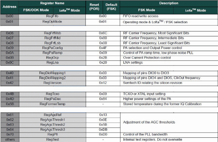
For a detailed examination, we refer you to the SX12xx series’ Datasheet: http://www.semtech.com/images/datasheet/sx1276.pdf
The registries 0x40 and 0x41 are destined to the I/O pins’ (they are 6: DIO0-DIO5) configuration; unfortunately these configurations have a different meaning, depending on the mode. In any case they are output pins, with the exception of DIO2, that can be a bidirectional one when it is configured for the continuous mode.
The other pins are especially useful in order to transmit some interrupt signals – that anyway may be viewed on the 0x3E, 0x3F (for the OOK/FSK mode) or 0x12 (for the LoRa mode) flag registries – outwards. The usage of interrupts allows an event-driven programming, but with the flag registers’ query it is possible, however, to keep the communication under control, also because the SX1278 automatically manages many steps.
Communication in OOK or FSK mode
As already mentioned, the communication in the OOK or FSK modes may be carried out by means of packets or in a free way, with the intervention of Arduino that will have the task to serialize/deserialize the data (via the D6/D9 pin, that may be connected to the SX12780’s DIO2).
It is however much more convenient and efficient to have the SX1278 to completely manage the communication, by using the packet mode and by loading/downloading the data from the queue, via SPI. The packets may have a fixed or variable length.
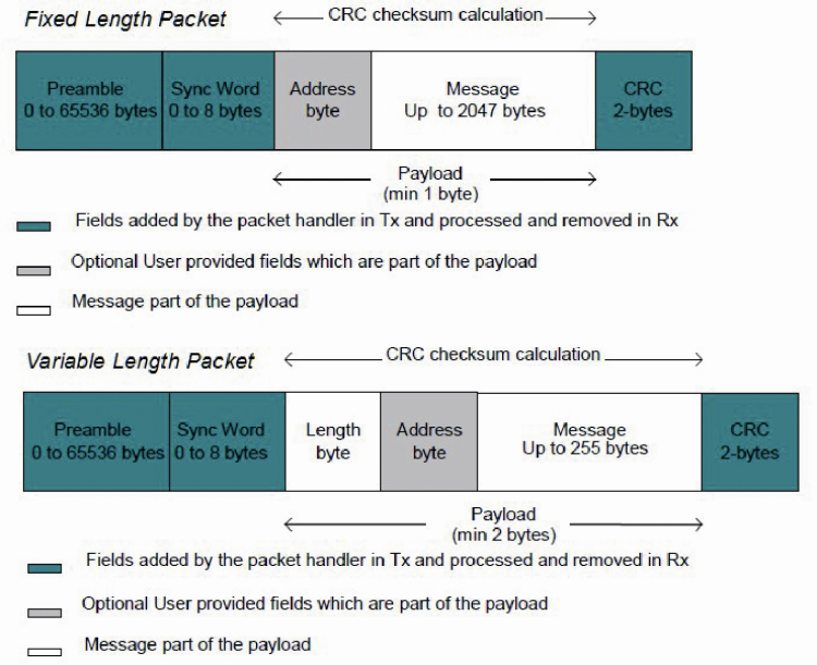
The packet having a fixed length is composed of:
- a preamble (having from 0 and up to 65.535 bytes), composed of a sequence of identical bytes (the length is defined by the registers 0x25,0x26); the kind of byte may be 0xAA (10101010) or 0x55 (01010101) (register 0x27);
- an address field (Sync), whose length (from 0 and up to 8 bytes) is defined in the 0x27 register, and the single bytes are defined in the registers going from 0x28 to 0x2F (but they cannot have 0 as a value); the field may define an address (one for the network or the terminal) since when it is present, it automatically determines the packet to be discarded – when receiving – if it does not correspond;
- a Payload (length defined in 0x32); it is the only one ending in the FIFO queue, and may have a minimal length of 1 byte, and a maximum one of 2048 bytes, and it is composed of:
– an user address (1 optional byte); it is an additional address.
– a message;
– an optional CRC, being of 2 bytes, automatically calculated by the chip.
As regards the user address, it is verified if the 0x30 register is configured for the “AddressFiltering”; in this case the packet will be discarded if the address byte does not correspond to the one configured in the register 0x33. The AddressFiltering may be carried out even with an additional control, by taking into account even the 0x34 register, where the “BroadcastAddress” has been included.
It is differentiated from the packet having a variable length, that has the payload’s first byte to indicate the length and thus it allows a message having a maximum of 255 bytes.
In the case of a communication in FSK/OOK mode, an essential setting is the one of the couple of registers, 0x02,0x03, that define in an accurate way the NRZ encoding’s baud rate. In fact, in the LoRa mode the proprietary protocol has other parameters.
As you can see, the SX1278 can be configured very much, in terms of modulation type, carrier frequency, baud rate and, along with many other parameters, it allows an accurate “tuning” of the communication, even if many parameters are defined with default values that are satisfactory ones, on average. It is almost an universal radio module, in the logic of SDR’s philosophy.
Since the configuration is a considerably variable one, we cannot be comprehensive in this context; those who want to deepen their knowledge, will be able to check the SX1278’s datasheet.
Let’s use the board to command the radio-controlled sockets
Let’s try to implement the communication protocol of the 220V radio-controlled power supply sockets (such as those of the Avidsen or Velleman systems) with this board, that contains such a performing and flexible radio system. At first, we could be tempted to use the board in the “continuous” mode and therefore as a normal radio module, by using the software library so to have Arduino to build the sequence of the pulses that are expected by the communication protocol. But we may do so much better: the protocol used by these system can be imagined as a sequence of 8 bits, whose baud rate corresponds to the frequency of the basic pulse.

Let’s keep in mind, at this stage, that the encoding used in the packets is of the NRZ kind and since it is not a RS232 transmission, it does not have the start/stop bits, nor the parity. Thus we may imagine to transform the protocol’s single frame of the radio control in a byte sequence, that is to say, a packet. It is enough to set the preamble and the Sync field (address) to zero, and to disable the CRC. Actually, the packet will be composed of 4 repetitions of this frame, as required by the radio control’s protocol, for a total of 64 bytes. The baud rate will be defined, depending on the inverse of the length of the basic pulse.
Let’s summarize the steps required in order to create this “remote controller”.
- To enable the boost output that is connected to the antenna, that as a default setting is not enabled (reg. 0x09); with the same register it is possible to regulate the transmission power (the default one is equal to 17 dBm, that is to say, 50 mW) which can be reduced to 2 dBm (1,5 mW) with 1 dBm steps, or it is possible to enable the extra maximum power of 20 dBm (100 mW).
- To set the chip in the “Sleep” operating mode (reg. 0x01) and to activate the non LoRa mode (reg. 0x01); in fact this essential commutation can only be carried out when the chip is in the “Sleep” mode.
- To set the OOK mode (reg. 0x01).
- To define the carrier frequency at 433,92 MHz (reg. 0x06,0x07,0x08).
- To define the baud rate (for example, 3.800 for Advidsen) (reg. 0x02,0x03).
- To define the 64-byte fixed length packet without preamble, address and CRC (reg. 0x25, 0x26, 0x27, 0x30, 0x32).
- To load the data in the FIFO queue.
- To bring the chip to the FSTX state (ready to transmit, reg. 0x01) and to wait some tens of microseconds.
- To bring the chip to the TX state (it transmits, reg. 0x01).
- To possibly bring the chip to the “Sleep” state (not needed, since the SX1278 automatically brings itself to the “Standby” state, as soon as the packet’s transmission is ended).

The quality and the efficiency of the SX1278 is è certainly greater than the one of the low cost radio modules considered in the previous article, even if the board has a quite moderate price; and moreover it completely frees Arduino from the burdensome task of serializing the pulse train. It turns out to be a reliable system with a good radio range.
Please keep in mind that the one proposed here is only one of the possible applications for the SX1278.
The Arduino library
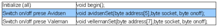
As you could have noticed, the management of the SX1278 component is not at all an easy one, because of the several registers and the many functions; therefore, we have written a library, so to simplify its usage with Arduino. First of all, the basic functions for reading and writing in the registers (by relying on the classic SPI library for Arduino) have been defined. Later, the functions for the SX1278’s main settings have been implemented. Anyway, the library is a work in progress, open to the implementation of the most sophisticated functions. In Table 1 you may see the main functions listed. On the basis of this library (SX1278 class), an additional library (REMOTEC class) has been created, aimed to the remote control of the 220V sockets.
Table1

In Table 2 the functions of this library have been described.
Table2
Consequently, the sketch in Listing 1 is a very simple one. The sketch reads the command from the serial port, and executes it by replying on the serial port with a string: “ON”,”OF” or “OK”. The sketch has been conceived (and verified) even for a usage with RandA. You may imagine the number of usages that can be easily implemented: from turning on and off alarms at a planned time, to the smart loads management.
Code
/********************************************************************************************************

* Commands (serial 9600):

*? : Responds with the name of the sketch (useful for Randa)

* ONX: on switch; where x = 1,2,3,4,5 (1,2,3 for Velleman) (reply "ON")

* Ofx: off switch; where x = 1,3,3,4,5 (1,2,3 for Velleman) (reply "OF")

* Av: prepare the sketch for the r Avidsen system (default) (reply "OK")

* Ve: prepare the sketch for the Velleman System (reply "OK")

* Adxxxxxxx: defines the address (es .: ad0200220 three-state) (only 5 char for Avidsen)

* PWX: adjusts the transmission power;

* Where x = 1 (5mW), 2 (10mW), 3 (20mW), 4 (50mW) (default), 5 (100mW)

**********************************************************************************************************/

#include “SX1278.h”

#include “REMOTEC.h”

#include <SPI.h>

#define ln 10

REMOTEC RC;

/ * Default values (initially on Avidsen with address 2020222) * /

byte addAv[5]={2,0,2,0,0};int alenAv=5;

byte addVl[7]={2,0,2,0,2,2,2};int alenVl=7;

byte* add=addAv;

int alen=alenAv;

int mode=1; //modo Advidsen

char buff[32];

byte sock;

byte onoff;

void setup()

{

Serial.begin(9600);

RC.begin();

setmodeavidsen();

}

void loop()

{

int c=Serial.available();

if(c>0)

{

Serial.readBytesUntil(ln,buff,32);

if (buff[0]==’?’) itsMe();

if (strncasecmp(buff,”on”,2)==0) commandSend(1);

if (strncasecmp(buff,”of”,2)==0) commandSend(0);

if (strncasecmp(buff,”av”,2)==0) setmodeavidsen();

if (strncasecmp(buff,”vl”,2)==0) setmodevelleman();

if (strncasecmp(buff,”ad”,2)==0) setaddress();

if (strncasecmp(buff,”pw”,2)==0) setpower();

}

}

/ * Recognition function; It lets you know that sketch is uploaded to the Arduino * /

void itsMe()

{

char name[]=__FILE__;

char* c=strchr(name,’.’);

if (c != NULL) *c=’\0’;

Serial.println(name);

}

void setmodeavidsen()

{

mode=1;

add=addAv;

alen=alenAv;

Serial.println(“OK”);

}

void setmodevelleman()

{

mode=2;

add=addVl;

alen=alenVl;

Serial.println(“OK”);

}

void commandSend(byte onoff)

{

byte sock=atoi(&buff[2]);

if (mode==1) RC.avidsenSet(add,sock,onoff);

if (mode==2) RC.vellemanSet(add,sock,onoff);

if (onoff==1)Serial.println(“ ON”); else Serial.println(“ OF”);

}

void setaddress()

{

int i;

if (mode==1){for(i=2;i<7;i++) addAv[i-2]=buff[i]-’0’;}

if (mode==2){for(i=2;i<9;i++) addVl[i-2]=buff[i]-’0’;}

Serial.println(“OK”);

}

void setpower()

{

byte power=atoi(&buff[2]);

if ((power<1)|(power>5)){Serial.println(“NK”);return;}

SX.setPower(power);

Serial.println(“OK”);

}
From Openstore
Semtech LoRa SX1278 Transceiver Module

[…] The LoRa shield: an Open Source Arduino’s long-range communication module. […]
[…] The LoRa shield: an Open Source Arduino’s long-range communication module […]
I want to transmit and recieve data over a long range And need a solution within a week. Can your product do it ?
This is a Long Range (LoRa) solution. Probably yes
[…] a previous post, you had the opportunity to discover a new Shield for Arduino, based on Semtech’s SX1278 chip […]
titlettxt
txt