

We emulate the TDG series remote controls using the GSM Shield.
It’s not been long since we presented our GSM shield for GSM/GPRS modules SIMCom, QUECTEL, FIBOCOM etc. that was born to be incorporated in Arduino-based projects involving cellular connectivity; now it’s time to move on to the first practical application, which in this case consists of replicating the operation of the bidirectional GSM remote control TDG133, which can manage two relay outputs and two voltage level inputs. For the occasion we have developed a series of commands useful to set the basic functions both by sending SMS and by sending commands through the serial monitor of the Arduino IDE. Both the electronics and the firmware development are based on the Arduino Mega 2560 board. This is for reasons of Flash memory and SRAM available for the application but especially for the availability of free I/O pins for the development of the project.
The platform on which we are going to develop our application is Arduino Mega 2560, widely supported by the GSM shield, as it is the only one that can provide a set of I/O necessary to manage input and output signals; specifically, the application proposed here needs:
-
two I/O to manage the digital outputs, at least in the basic application, but the project supports up to eight digital outputs and therefore considers the use of eight I/O lines;
-
two I/O to manage the digital inputs, that can be configured to work as high or low level active or on variation; actually up to eight input lines are available;
-
as far as the signalling LEDs are concerned, the ones already present on the GSM demoboard are used.
For the functioning logic we refer to the TDG133 remote control, of which we will replicate the functions compatibly with the available hardware. We remind you that TDG133 is a bidirectional remote control module that allows you to remotely control the status of two relay outputs, in bistable or monostable mode, by sending specific SMS completed by a password. Moreover it allows the acquisition of the status of two optoisolated inputs.
The commands can come from telephone numbers stored in a list of up to eight numbers to which the device sends SMS and voice calls when it considers activated, according to the settings made during configuration, the digital inputs. The TDG133 remote control can also function as a gate opener, a mode to which up to 200 telephone numbers can be matched.
HARDWARE BLOCK diagram
Having established what TDG133 did we also know what our project needs to do, which that system needs to emulate using Arduino or compatible hardware.
The block diagram gives an idea of the electronics of our GSM Shield based remote control.
Like the TDG133, this telecontrol provides two digital inputs and two relay outputs. In our application we provide up to eight digital inputs, that can be active at high or low level, and eight digital outputs that can drive up to eight relays; actually, this availability is hardware, because the current firmware of Arduino Mega 2560 allows to manage only two digital inputs and two digital outputs and who wants to use all 8 lines will have to put hands on the code.
The block diagram shows the logic with which the application has been developed.
-
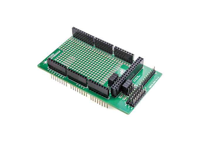
Shield Telecontrol board, highlighted with a green square, is mounted on the GSM Shield, which in turn is plugged into Arduino Mega 2560.
-
The Telecontrol Shield provides up to eight digital inputs and through a board-to-board jumper it is possible to select if the input is active at logic high level, so the pull-down must be inserted, or if it is active at logic low level, so the pull-up must be inserted.
-
You can generate the event by bringing the desired input to GND or +5Vdc. To do this you can use the usual laboratory jumper cables such as Open Electronics code “7300-JUMPER50”.
-
Shield Telecontrol provides up to eight digital outputs with which it is possible to control cards with two, four or eight relays; all these cards mount relays with +5V coil voltage. In this case we refer to the products “2846-RELAY2CH”, “2846-RELAY4CH” and “2846-RELAY8CH” of Open Electronics. Also, jumper cables must be used to connect relay boards.
-
Power supply to Remote Control Shield can come either from Arduino Mega 2560 through USB type B cable, or from GSM Shield micro-USB socket, through micro-USB cable.
-
The connection via USB type B cable also allows the programming of the Arduino Mega 2560 board, as well as to send configuration commands via the serial monitor of the Arduino IDE.
-
Through the monitor you can also receive information about the status of events intercepted during operation, send and receive SMS, etc..
-
If you want to monitor AT commands sent from Arduino Mega 2560 to GSM module you can use the usual USB/TTL converter (cod. FT782) connected to proper connector on GSM Shield. The FT782 electronics also allows to bring 5Vdc power supply to the GSM Shield.
ELECTRICAL DIAGRAM
The electrical diagram of GSM Shield has already been published in the issue n. 231, so here we will describe only the circuit of Telecontrol Shield, whose wiring diagram is shown in these pages; it is something very simple that takes the connections of port PA0÷7 of Arduino Mega 2560 and through an on-board jumper distributes them to manage the output digital lines used to drive the relays. It also takes the signals of port PL0÷7 of Mega 2560 to manage the input digital lines. These lines are all on the 36 poles connector (18 poles x 2 lines) of Arduino Mega 2560 to which are also connected the six LEDs mounted on the Remote Control Shield and used for generic purposes (Port PC0÷7).

Regarding digital inputs it is possible to set if they must be active with high or low logic level. Jumper (J1÷8) selects the operating mode; in particular if this jumper is inserted in position 1-2 the 10 kohm pull-up resistor is inserted and then the input is active at low level, while if the jumper is in position 2-3 the 10K pull-down resistor is inserted and then the input is active at high level.
For each input we have arranged a contact point on connector CN5 to be used, through jumper cables, to activate the corresponding input that is +5V if active high or GND if active low. We have then prepared two other connectors with 8 poles each, signed CN1 and CN2, to which we have respectively brought the lines +5Vdc and GND. In this way, for each of the eight inputs there is a corresponding point +5Vcc or GND to be used for the simulation of the state variation on the input.
As for the outputs these have been simply reported on the CN4 connector together with the +5V and GND line necessary to supply the auxiliary relay boards to be used for this application.
To complete the demo board we have also reported the free lines, present on the other countless connectors of Arduino Mega 2560, so as to give the end user the ability to use the function associated with them. All the lines already occupied for the management of the GSM card are not reported.
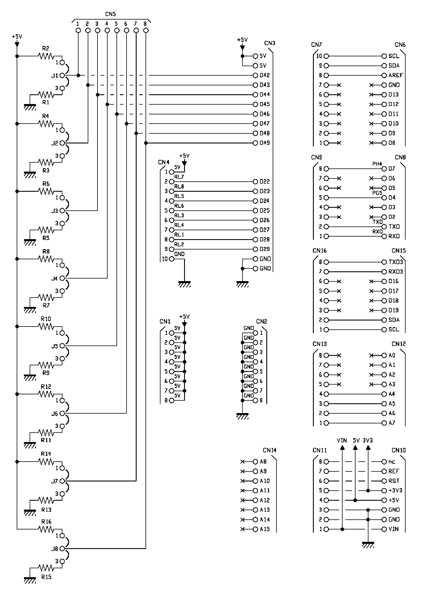
In order to make the demo board more versatile we have also prepared a section on the PCB that acts as a prototype development section where users can mount components at will to develop their own applications. The pitch between pads is the usual 2.54mm. This area provides over 315 individual pads free of potential, plus a reduced set of pads to which the +3V3, +5V and GND lines have been brought.
THE SKETCH
The architecture on which our application is based is based on the EEPROM of the ATmega 2560 for storing a series of parameters, including SMS to be sent in case of alarm and the memory of the SIM, inserted in the GSM module, for storing phone numbers enabled to manage the remote control system.
We have made this differentiation because, although very large, the EEPROM of the ATmega 2560 is not large enough to store all 208 phone numbers managed by the remote control. It was therefore decided to exploit the memory made available by the SIM to store phone numbers in the phonebook, with their description, as is done in common cell phones. This approach also gives us the opportunity to show how to exploit the library functions created for the management of AT commands necessary to read, write or delete the phonebook.
After this short introduction we can start with the description of how the sketch containing the remote control management code has been structured. First of all, the code contains not one but two sketches that, obviously, do not work simultaneously. This is made possible by the fact that there is a directive to the compiler that allows us to select whether to use the factory parameters programming code in the EEPROM of the ATmega 2560 or to activate the remote control management code. The directive that allows us to select which sketch to run is as follows:
#define WRITE_DEFAULT_DATA_EEPROM
This directive is located at the top of the “GSM_TDG133.ino” file. When this directive is written, the remote control code is compiled and executed, vice versa the code concerning the programming of default parameters in the EEPROM memory is compiled and executed. The parameter programming code does not reset the phonebook present on the SIM inserted in the GSM module. The deletion of any phone numbers in the phonebook is done by sending appropriate command strings which are interpreted and managed by the remote control code that consequently will send appropriate AT commands to delete one or all contacts in the SIM.
The code that deals with the programming of the factory parameters on the EEPROM can be found in the file “_SetupEeprom.ino” where at the top of it we find, in tabular form, the mapping of the EEPROM memory with indication of where the data are stored and how much they occupy in memory.
This mapping is designed to manage the texts of the two input alarms (Input 1 and 2) and their management parameters as well as the enabling/disabling of SMS sending to the first eight numbers in the phonebook. We see the mapping in Fig. 2. As you can see, there is space left over to add new text messages in case you decide to expand the input section from two to eight total inputs.
Fig. 3 shows the flowchart of the EEPROM programming sketch, where the steps described below follow one another:
-
Using appropriate library functions, we obtain the starting addresses in EEPROM for the management of PIN codes, PUK etc. used by our library for GSM modules; looking at the table with the EEPROM mapping we can see that the codes under examination are at the top.
-
Following this is another library function to activate the serial used for debugging. That is the serial that allows, through the Arduino IDE serial monitor, the user to receive a series of information from the running sketch and eventually send command strings to the sketch.
-
Before setting the default values, a function is executed that resets the content of the EEPROM memory, that is, it sets to 0x00 all the memory locations that have a different value stored in it.
-
The setting of the factory parameters starts with the writing of the PIN, PUK etc. codes.
-
Then follows the function to store the system password (default value “12345“).
-
Then follows the saving of the flags.
-
Finally, the strings used to send SMS are stored.
-
The system waits two seconds and then it performs a complete re-reading of all the EEPROM in order to verify that its content corresponds to the newly programmed factory parameters; first of all, the default parameters are printed on the serial monitor in string format with a short description of the content, followed by a re-reading of the EEPROM and relative printing on the serial monitor in hexadecimal + ASCII format.

As you can see in Fig. 2, at the top of the EEPROM content there are the PIN, PUK etc. codes needed by our GSM library, followed by the system password (Starting address in EEPROM: 0x0050). Finally, the strings to be used for sending SMS are displayed. Below the displayed data is then reported the entire contents of EEPROM memory starting from address 0x0000 up to address 0x0FFF. Now if the directive:
#define WRITE_DEFAULT_DATA_EEPROM
is written, the main sketch containing the remote control code that we are going to analyse is compiled and executed.
Let’s go back to the flowchart of Fig. 3 and study it starting from the function “void setup()” which is used to initialize the GSM library and to preload in memory a series of parameters stored in EEPROM.
So during initialization:
-
by means of appropriate library functions we obtain the starting addresses in EEPROM for the management of PIN, PUK codes used by our library;
-
configuration of timer 5 used by the sketch for the management of time variables such as timers used for debouncing digital inputs, timeout for the management of waiting times etc. (the time base used for the timer is 2ms). (the time base used for the timer is 2ms);
-
the configuration of the digital inputs used for the creation of the sketch takes place;
-
the configuration of the digital outputs used for the creation of the sketch is performed, as well as the digital outputs used by the GSM library for the management of the LEDs connected to it;
-
test routine on LEDs on GSM Shield;
-
set the interrupts used by the GSM library for its correct operation;
-
enable and configure the UART interface used for debugging via Arduino IDE Serial Monitor;
-
enable and configure the UART interface used to send AT commands to the GSM module;
-
turn on the GSM module and start the state machine needed for its correct management.
This is followed by the reading in EEPROM of the parameters used in the sketch, such as:
-
system password; default value “12345“;
-
system flags including the enabling of SMS alarm notification and relative voice calls;
-
inhibition times of the digital inputs
-
digital inputs observation times;
-
maximum number of SMS to be sent in case of input alarm;
-
telephone number to send ECHO SMS;
-
door opener function timeout.
Also during initialization, the initial setting of the state of the digital alarm inputs is performed, as well as the setting of all the state machines used to manage the sketch and related functions. Once initialization is complete, the system enters the main and the contents of the “void loop()” function are executed indefinitely.

The following are then executed:
-
reading of alarm digital input status and relative debouncing;
-
management of the functions associated with the alarm digital inputs.
-
management of digital outputs used for relay management.
-
management of the machines with states inherent to the GSM library both during the GSM module initialization phase and during the steady state management for the sending of AT commands necessary for the sketch operation.
The following are all the functions and machines with states for the management of all the functions made available by the remote control:
-
commands for telecontrol configuration sent through the serial monitor;
-
commands for remote control configuration sent through SMS;
-
SMS sending according to the recorded event;
-
voice call execution according to the recorded event;
-
management of ECHO function, if enabled;
-
management of gate opening functions;
-
LED management according to the recorded event.
In detail, let’s examine the operation of the function “void ProcessStateMachineGsm(void)“.
At the top of the function we have the code, already used in the past, for the management of the GSM library and its features that, through a conditional construct “if – else“, determines if it is performing the initialization of the GSM module or if it is running and therefore ready to process AT commands sent from the sketch to the GSM module. So, looking at the block diagram, if initialization is running, all code downstream of the conditional block will not be executed.
Once the initialization is completed, the process will be able to advance and process the library functions to manage the AT commands needed by the sketch plus all the other functions needed to realize the application. Here is the code that distinguishes the initialization process from the steady state process:
Gsm.ExecuteUartState();
if (Gsm.GsmFlag.Bit.GsmInitInProgress == 1) {
Gsm.InitGsmSendCmd();
Gsm.InitGsmWaitAnswer();
} else {
Gsm.UartContinuouslyRead();
Gsm.ProcessUnsolicitedCode();
Gsm.GsmAnswerStateProcess();
**** User code used to develop the sketch ****
}
As you can see the “if – else” construct contains a series of library function calls, one of which is always called because it is outside the “if – else” construct, that is “Gsm.ExecuteUartState();” that manages the state machine of the serial communication between Arduino Mega 2560 and the GSM module mounted on the board. The other functions are dependent on the value assumed by the “Gsm.GsmFlag.Bit.GsmInitInProgress” flag. Part of the user code, depending on what you have to do, can be placed inside the “else” section. Usually are put all those functions that need to send an AT command to the GSM module and therefore must be executed when the system is up and not before.
Let’s continue with the analysis of the flow-chart; after the initialization we have to manage a series of possible situations including the first incoming voice call to record the first phone number in the list. The sketch, at startup, analyses the SIM phonebook looking for a valid phone number in the first memory location. If it doesn’t find anything, for five minutes it waits for an incoming phonic call, from any number, which will be recorded in the phonebook as “ADMIN“.
It is not mandatory but it is always a good idea to record a phone number in the phonebook combined with a descriptive text because when you receive incoming SMS or voice calls automatically the GSM module will return a text string with the header “+CLIP” to indicate whether the phone number is present or not in the phonebook. If the string, in addition to the phone number, also contains the description we will have the confirmation that this number is registered. With this information then it becomes easy to establish in which memory location the number is located to understand if it is part of the first eight or if it is one of the phone numbers with only gate-opening function. The fact of receiving an “Unsolicited Result Code” from the GSM module depends on the type of configuration that our library adopts during the initialization of the module, otherwise you would not receive such information (Commands AT+CRC and AT+CLIP).
The yellow LEDs LD6 and LD7 flash alternately while waiting for the first incoming phonic call. If the five minutes expire before an incoming phonic call is received, the system becomes fully operational and appropriate string commands are used to configure the phone numbers in the phone book, to be sent either via SMS or via serial monitor.
Once the test on the necessity to wait for the first phone number is passed, the system processes some functions that have the purpose to send AT commands to the GSM module in certain conditions. Let’s see which ones: general purpose AT commands sent in a continuous cycle to the GSM with a pause of one second from one command to the next. These AT commands are intended to acquire a set of information from the GSM module, which are useful to the system for its operation. The flow can be interrupted when events occur such as an alarm or other that require the sending of other AT commands more priority. The generic AT commands used are:
AT+CREG → GSM network registration information;
AT+CSQ → GSM signal quality information;
AT+CPAS → GSM module status information (to know if it is busy or not);
AT+COPS → operator information;
AT+CPMS → SMS input/output storage preferences;
AT+GMI → GSM module manufacturer information;
AT+GMM → GSM module model information;
AT+GMR → FW revision information loaded in the GSM module;
AT+GSN → IMEI code;
Then there are specific AT commands sent as a result of sending command strings. For example:
AT+CPBR → AT command for reading a memory cell from the phone book;
AT+CPBF → AT command for searching a phone number in the phonebook
AT+CPBW → AT command for writing/deleting a phone number in the phonebook
AT+CMGD → AT command to delete an SMS from the SIM memory.
The following is the code portion for the management of the command strings needed to configure the remote control, sent both from the serial monitor and via SMS. The strings that can be sent (which we will show shortly) are the same regardless of whether they are sent through the serial monitor or via SMS. Next we have a series of conditional blocks in order to check if you have to execute particular functions made available by the sketch if properly configured and enabled. In particular we have:
-
sending, if enabled, of the SMS at system power-up (power return); this functionality must be enabled by a proper command string and the SMS content can be the default one stored in EEPROM or a different string programmed by the user through a proper string command;
-
sending, if enabled, of the start-up SMS; this functionality must be enabled by a specific command string; the content can be the default one stored in EEPROM or a different string programmed by the user through a specific string command;
-
sending of alarm SMS according to the status of the digital inputs; the content of the SMS to be sent can be configured by the user using the appropriate string command; the alarm SMS can be sent only to the first eight numbers in the phone book if the number has been enabled to receive such SMS (in addition to sending an alarm SMS to the first eight numbers in the phone book, the system can also make a voice call to these numbers if enabled);
-
send an SMS report containing the status of the inputs and outputs (this function must be programmed);
-
enable/disable the function with proper string command;
-
set how often the report SMS must be sent;
-
the message is sent only to the first number in the phonebook;
-
ECHO SMS sending. If you enable this function, all received SMS that have no connection with the command strings used by the remote control will be sent to a previously selected phonebook number;
-
sending of SMS in response to string commands sent via SMS;
-
finally follow the functions for the processing of incoming SMS and possible voice calls always in input.
What has just been explained is the framework of the sketch, which, as usual, is divided into several files, which are described below.
• GSM_TDG133 → main file containing all declarations of variables, constants, directives to the compiler, string commands stored in the Flash of the microcontroller and their unique numeric codes, text strings used for printing on the serial monitor etc. as well as the functions “void setup()” and “void loop()”.
• AT_CmdFunction → file containing the management code of the generic AT commands used in the sketch and management of the GSM library functions;
• DigitalInput → file containing the code for managing the digital inputs;
• DigitalOutput → file with the code for managing the digital outputs (relays);
• OutComingSmsVoc → file with the management code for SMS and outgoing voice calls;
• ProcessStringCmd → file containing the code for decoding string commands received from the serial monitor or via SMS;
• SerialStringCmd → file with the code for managing the strings received from the serial monitor or via SMS;
• TimerInt → file containing the code for managing the TIMER 5 used for the time variables necessary for the sketch;
• SetupEeprom → file containing the code for managing the programming of the EEPROM factory configuration.
Moreover, the subdivision on more files allows to keep the code tidier and to divide it in well-defined sections.
Components List:
R1, R2, R3, R4, R5, R6, R7, R8, R9, R10, R11, R12, R13, R14, R15, R16: 10 kohm (0603)
CN8, CN10, CN12, CN14, CN15: Strip Arduino 8 vie (5 pc.)
CN6: Strip Arduino 10 ways (1 pc.)
CN3: Strip Arduino 2×18 ways (1 pc.)
CN1, CN2, CN5: 8 ways male strip (3 pcs.)
CN7: 10-way female strip (1 pc.)
CN9, CN11, CN13, CN16: 8-way female strips (4 pcs.)
CN4: 10-way male strip (1 pc.)
J1, J2, J3, J4, J5, J6, J7, J8: Strip male 3 ways (8 pcs.)
Various:
– Jumper (8 pc.)
– Printed circuit board S1468 (56×98 mm)
CONCLUSIONS
Well, for the moment we stop here; in the next and last episode we will deepen the programming aspects, we will explain the use and the syntax of the commands to give and we will conclude describing the signalling provided by GSM Shield LEDs.
FROM OPEN STORE
Universal GSM Shield for Arduino and Raspberry Pi
