It detects humidity through two sensors which are to be used alternatively to let us know when there is water on the ground because it’s raining, or when the water level in a flowerpot is too low and it needs watering.
How can we know the right value of the soil humidity in a flowerpot? Experience surely helps, or we can just wait and see when the plant starts to wilt and dries out: in this case the method isn’t ideal because it would be too late to do something about it, in fact even if we water the plant we might not be able to save it.
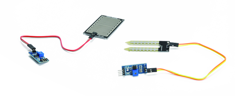
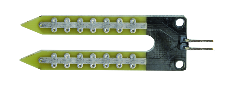
Here in this post we show you how, by making use of a really simple circuit, we can provide the two different functions based on the sensor we connect to it: in one case we are going to stick two metal prongs in the ground and check if there’s enough moisture; in the second we’ll have a rain sensor (a wet sensor, in general terms…) that makes use of an inter-digitized electrode printed circuit for the detection.
In the end, the circuit is the same and works by detecting a sufficient quantity of water, like we are going to see in the circuit diagram, in order to trigger a threshold circuit, taking advantage of the intrinsic electric conductivity of mineral water, i.e. common water and not the distilled kind (which is theoretically an insulator). The difference is that in the first case we need a signal when there is a small amount of water closing the two contacts and in the second one we have a signal when the water level is more than enough.
The rain sensor can be paired with garden sprinklers and water stagnation sensors; irrigating in these cases is pretty useless: when is raining or when it has just finished raining.
Circuit diagram
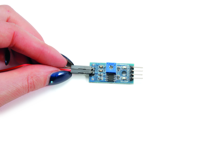
The circuit is basically composed of a voltage comparator (one of the two contained in the U1 integrated circuit; the other, U1a, has been left disconnected) that allows executing two different functions when the same event is detected; the event is the decrease of resistance value between terminals + and – (A0 and GND), which basically corresponds to the (in the digitized-electrode or fork ) sensor getting in touch with water, when there is enough water to short-circuit the two electrodes of the sensor itself.
The computer also works in non-inverter mode, in that it doesn’t get the reference voltage on the inverter input (6-pin) and want to compare on the non-inverter one; furthermore, there is no feedback, so no hysteresis, therefore the commutation of output from voltage level high to low takes place for the same voltage on the non-inverter input that determines the passage from level low to high.
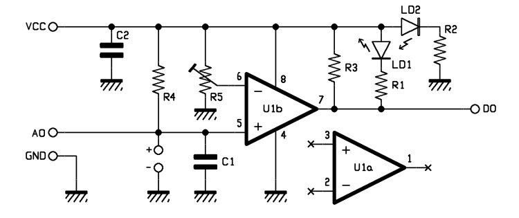
Since reference voltage applied to 6-pin (inverter input of the comparator) is obtained by a trimmer mounted as a potentiometer, we can adjust the reference at will, from 0 V to full power voltage, and therefore play on the circuit sensitivity in the maximum extent allowed. The comparator is contained in a LM393D, which is a double comparator (so it contains two operational stages specifically designed to function as a comparator) and therefore has an output that can give the maximum possible range, although, when it’s on level low, it doesn’t exactly go down to 0 V (which is a specific aspect of rail-to-rail op amps) but it stays on a few hundred of millivolts. Furthermore, U1b output is open-collector, so it requires a pull-up resistance to reach level high, which in this specific case is the R3, and we have to take note of its resistance value when we put a load on the output by connecting a utilizer that ends up on ground; in this case the voltage that can be effectively picked between the output pin (7) and ground will depend on the current requested, that is the divider ratio, considering that the exact value can be obtained with the formula:
Vdo = Vcc – (Iu x R3)
where Iu is the current at the circuit output, that is by the DO contact (Digital Output, since it provides a digital signal).
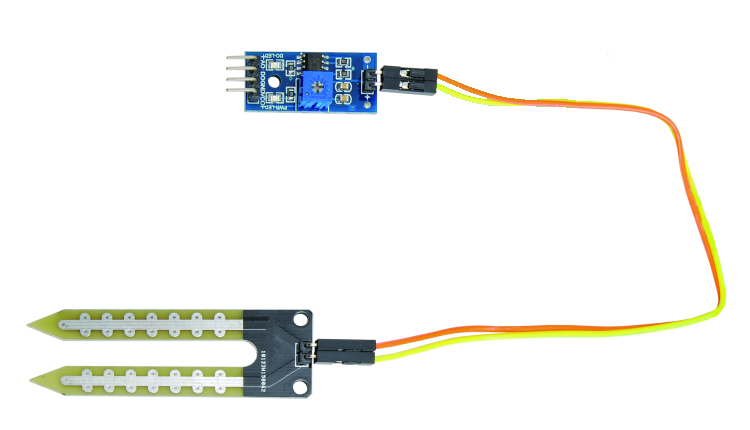
If you need to connect the DO contact to a circuit in which input resistance would determine an excessive lowering of the voltage provided, you can decrease R3 value without going below 1 kΩ, because decreasing R3 too much would increase power consumed by the circuit when the comparator output is low level and current passing through 7-pin is enough to raise the corresponding voltage to level low. With that said, let’s see how our circuit works: if we connect a fork sensor between terminals + and – (A0 and GND), a fork sensor composed of a printed circuit shaped with two engraved electrodes reaching almost to the tips, that we are going to stick into the ground, the soil humidity will determine a certain resistance between the two terminals, this resistance will create a voltage divider with R4, connected between Vcc and 5-pin of the U1b. The divider ratio with determine the voltage applied to the comparators input, so, reference voltage provided by the trimmer being equal, the more humidity there is in the ground, the lower the voltage needed for commutation of the comparators output will be.
The latter is at level low (causing the LD1 LED to light on) when the soil is very humid and the resistance is such to keep voltage on 5-pin of the U1b at a lower value than the one applied to the 6-pin by the trimmer; same things apply for the DO terminal.
On the other hand, when the soil starts to dry out, water percentage sensibly decreases and voltage between A0 and GND goes up, until it exceeds the comparator’s reference voltage, causing the output to switch from low-level to high level; now the LED turns off, which means we have to add water. With the trimmer, we can adjust the signal according to the type of soil and the plant we want to monitor, remembering that the more the sensor is near to the ground limit, the more humid the soil must be in order to turn on the LED and vice versa (the LED will turn off way before soil turns to try).
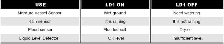
Now, let’s see the circuit functioning as rain sensor: in this case, we are going to connect the dedicated sensor composed of a printed circuit with inter-digitized tracks to the DO and GND terminals (any sensor of this type is good, even if it’s not on a PCB or if it is composed of a circuit printed on fiberglass where tracks are separated by gaps). The functioning, in this case, is the other way around, because we are going to see the LED lighting on when there is water, and water density on the electrodes determines the resistance and the voltage applied at the input of the U1b comparator. So, when water wets the electrodes and short-circuits them and determines a resistance which is the winter of two bring the voltage on A0 to a lower value than the one on 6-pin, the comparator’s output turns off (DO goes high) while when rain stops pouring and water on the terminals dries out, voltage between 5-pin and ground exceeds the voltage between the trimmer’s slider and ground and the output goes back to level high, and the LED turns off. Therefore, in this application the LED is off when there is no rain and it is on when it’s raining; if we use the circuit to signal flooding, the LED turns on when there is water in the ground and it turns off when soil is dry (same thing if we use it as a liquid level detector). A recap of the LED functioning is provided in table 1 for all the application scenarios we can think of.
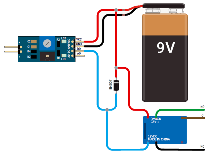
The circuit can be easily powered with a 9 V battery or even three AAA batteries connected in series; power voltage should be decided also in relation to the circuit functioning; the circuit can also make use of the DO terminal to be for instance interfaced with a microcontroller or a Logics unit. This output can be used for instance inside a greenhouse to monitor plants condition and get a notification when one or more plants require watering (you can create a dedicated PC software for this situation) or detect rain or flooding, or to detect the maximum level of a liquid inside a tank.
Power is signaled by the LD2 LED lighting on (on Vcc+), which current is limited by R2 resistance.
Hands-on realization
If you want to use the system to signal the rain status to a weather station, connect the DO terminal and ground to the input of the station, making sure to check the required voltage and adjusting the circuit power, still within the comparator limits (12 V).

Same thing if you want to connect the circuit to a technological alarm or any other kind of electronic system (even Arduino-based) for data gathering.
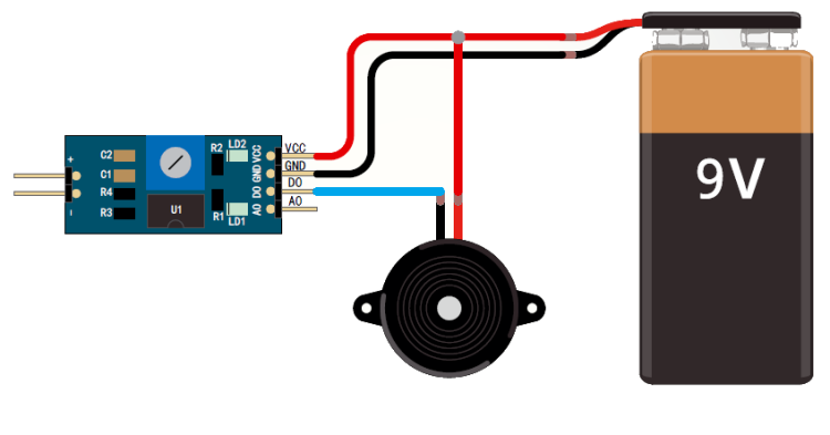
The wiring scheme on the following page proposes various application examples and related connections. Interdigitated-contact sensors are placed to the ground and, when it rains, the water will join them together, determining a strong lowering of resistance between the electrodes compared to the dry condition (in this case the resistance is theoretically infinite); by reading the sensor status with a logical input equipped with a pull-up resistor we find a logic 1 on standby, while if the sensor is wet, waters resistance acts as a voltage divider with the pull-up resistor and determines a logical 0. Remember that if you want to detect rain, flooding etc. you have to connect the inter-digitated rain sensor to terminals + and -, while you need the fork sensor to monitor soil humidity in flowerpots. The fork sensor is also useful if you want to create a liquid level detector inside a cistern or another kind of container. Also remember that you can freely adjust the circuit’s sensitivity (i.e. decide the amount of water humidity needed to provide the signal through D0 or LD1 LED) by adjusting the trimmer on the board; to be exact, if you bring the slider near the upper power limit you will need more water, while if you rotate it toward ground you will need only a small quantity of water or humidity.
From openstore

[…] Boris Landoni writes about a new open source rain and humidity sensor project: […]