The latest robot from Waveshare, it adds interesting features to the qualities of its predecessor.
You were able to appreciate the instructional robotics platform on wheels called Alphabot, in an article dedicated to it, and you were able to see it in its version with Arduino controller. Alphabot, we remind you, is a robot on three wheels with a base support in both Arduino Uno and Raspberry Pi, therefore allowing to develop robotics applications with either prototyping platform and take advantage of the computing power of Raspberry Pi or the simplicity and widespread ample library’s choice in sketches peculiar of the Arduino world.
Based on the Alphabot experience, Alphabot2 was born, which is oriented to the international STEM standard (Science, Technology, Engineering and Mathematics), ideal to have fun experimenting with a complete, easy-to-use robot, suitable for both kids at their first experience with programming, and for enthusiasts dabbling in electronics.

Fig. 1
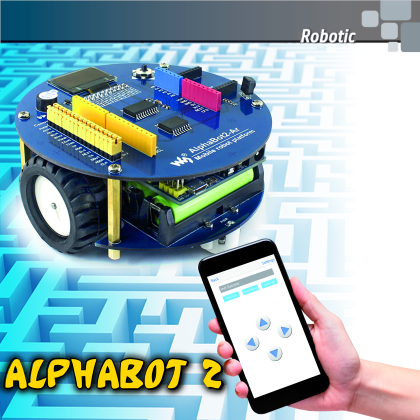
Alphabot2 is a robot based on wheels with reduced dimensions (around 11 cm of width and 5,6 cm of height) devoid of onboard logics but compatible with Arduino boards. Fig. 1 proposes the assembled and complete robot. Alphabot2 was designed in order to implement all the major functionalities of self-propelled wheeled robots such as line following, obstacle avoiding, remote controlling, but it is also complete with different peripherals such as the display and joystick with which you can experiment on different applications; major features and functionalities are recapped in Fig. 2.

Fig. 2
Alphabot2 Hardware equipment
AlphaBot2 is composed of two circular frames, doubling as printed circuit and chassis for the robot. The bottom one has two motor reducers with high precision, low noise metal cogs, commanded by a double H-bridge driver with high-efficiency based on the TB6612FNG, the wheels are 42 x 19 mm, made out of high grip rubber. We still have five ITR20001/T infrared reflection linear sensors, two ST188 front infrared obstacle sensors, and an HC-SR04 ultrasound sensor. The hardware is finished off by four Neopixel LEDs, independently and serially controlled.
Anyways, these are SMD latest generation components (except for the ultrasound sensor) of the highest quality. The power is provided by two, 3.7 V 14500 lithium polymer batteries, with 800 mAh capacity, providing long working life with reduced weight and encumbrance. There is no internal recharge in the circuit, therefore, once the batteries are dead, they must be removed and inserted into the dedicated battery charger.
The upper frame has a housing for the Arduino board (not included in the kit), 0,66 inches, 128×64 yellow/blue bicolour OLED display, a TLC1543 AD converter, a joystick, a buzzer and an expansion module for I/O is based on the integrated PCF8574. The latter component is used to optimize the use of the I/O lines of the Arduino board, which are not enough to handle the many onboard peripherals.
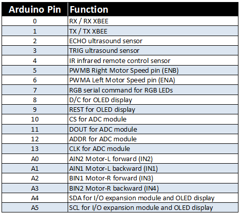
On the upper part, there are also all the classic connectors of an Arduino board and an XBee-compatible connector. A connector called Control JMP is also available, allowing to redefine the features of the Arduino pin in relation to the hardware on the board. For all the details on the functionalities of the Arduino pin, please see Table 1.
Table1
The ADC module is used to measure the batteries voltage and the light values of the five line sensors. The expansion module connected to the I²C port is used to read the status of the joystick keys and the two front distance sensors; these have a digital output, therefore they allow to determine the presence of an object in front of the robot but they do not provide information on the distance.
Alphabot2 kit
Let’s start building Alphabot by checking its composition and its available kits on the market; everything can be found in an assembly kit containing:
- two circular printed circuits with all the components already mounted except for the ultrasound sensor;
- the ultrasound sensor;
- a flat-cable to connect the two printed circuits;
- an infrared remote control;
- spacers and screws for the assembly;
- a screwdriver;
- the programming cable.

Fig. 3
Other tools needed for use in the robot (not included in the kit), an Arduino board, the two batteries in the battery charger. Optionally (not included in the kit) the Xbee-compatible Bluetooth module.
Alphabot2 Test
Waveshare thought of everything and, besides a well-designed hardware part, they provide a series of software applications, some of which are useful in order to test the robot, some other implement in more advanced functionalities. The files are available in an archive named AlphaBot2-Demo. For now, we only want to check if everything works correctly, therefore, by acting on the dedicated switch found on the bottom side, we power up the robot, and the LED label the PWR turns on. We connect the Arduino board to the PC using the USB cable and launch Arduino’s IDE, then we prepare to program the robot.
If we simply connect the Arduino board to the PC and leave the robot off, we can still use all the functionalities but the motors will turn the slow were since they are powered by 5 V instead of the around 7 V voltage provided by the battery. The provided sketches use specific libraries that we have to install, therefore we copy the files found in the subfolders named libraries in the libraries folder of Arduino’s IDE. The first sketch to upload, available in the subfolder called di mall, is called Run_Test.ino and allows to test the functionality of the motor, which will be activated at low speed.
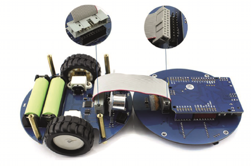
Fig. 4
Using the Alphabot2
Now we can turn our attention to managing the motors and reading the line sensors. We also see some practical examples on the combined use of motors and sensors, in full educational robotics style. The entire robot is moved by two motor reducers with 5 V nominal voltage and a 30:1 reduction ratio capable of moving the robot with very high precision at a not so low speed, since it can reach 60 cm/sec.
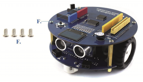
Fig. 5
the robot’s ability is insured by the use of two ball-casters, one of the front side and one on the backside.
The driver command in the motors is a modern TB6612FNG double H-bridge providing three command lines in order to have the complete control over the motors; from the rotation direction to the rotation speed and also the braking function. Unfortunately, there are no encoders which would have allowed to determine the distance covered by the robot or stabilize the rotational speed which is on instead influenced by the battery voltage. Fig. 6 and Fig. 7 detail the components of the Alphabot2 scene from both sides.

Fig. 6
Arduino lines from A0 to A3 and its digital lines 5 and 6 are used to control the motors. From a software standpoint, the motor control is handled as in the most classical shields (motor shields, in shorts…) Based on the L298 integrated, with two lines dedicated to the rotation direction and the third one dedicated to setting the rotational speed, thanks to a PWM signal.

Fig. 7
Before using the commands for the motors, we have to correctly set the control lines of the power driver; this setting is shown in List 1.
List1
#define PWMA 6 //Left Motor Speed pin (ENA)
#define AIN2 A0 //Motor-L forward (IN2).
#define AIN1 A1 //Motor-L backward (IN1)
#define PWMB 5 //Right Motor Speed pin (ENB)
#define BIN1 A2 //Motor-R forward (IN3)
#define BIN2 A3 //Motor-R backward (IN4)
void setup() {
// set output lines
pinMode(PWMA,OUTPUT);
pinMode(AIN2,OUTPUT);
pinMode(AIN1,OUTPUT);
pinMode(PWMB,OUTPUT);
pinMode(AIN1,OUTPUT);
pinMode(AIN2,OUTPUT);
}
In order to set the robot’s movement we need to set signals AIN1, AIN2, BIN1, BIN2 and specify the rotational speed using the analogWrite instruction, using an integer value from 0 to 255 for the speed variable; to this regard, we invite you to take a look at the code below, showing how the robot moves traveling at the speed defined in speed:
analogWrite(PWMA,speed);
digitalWrite(AIN1,LOW);
digitalWrite(AIN2,HIGH);
analogWrite(PWMB,speed);
digitalWrite(BIN1,LOW);
digitalWrite(BIN2,HIGH);
the rotational inversion of the motors takes place by adjusting the levels of the previously mentioned lines, as shown in the code below, where the robot goes for words at speed:
analogWrite(PWMA,Speed);
analogWrite(PWMB,Speed);
digitalWrite(AIN1,HIGH);
digitalWrite(AIN2,LOW);
digitalWrite(BIN1,HIGH);
digitalWrite(BIN2,LOW);
The value of the speed variable doesn’t actually set the rotational speed, but just the voltage percentage to provide the motors, the maximum value of 255 (maximum value that can be expressed with one bite) allows to have all the battery voltage on the motors and therefore the maximum rotational speed. We suggest taking the Run_Test.ino ‘s catch as a reference to use as a base in order to develop your applications involving the motors.

Fig. 8
As described in the previous article, Alphabot2 is also equipped with five ITR20001 infrared line sensors with analog output, perfect to precisely detect the surface on which we are operating. In order to save on analog lines, all the five sensors are connected to a 10-bit A/D converter with a serial output labeled TLC1543. On a software level, we have to use the TRSensor.h library which provides a series of functions in order to make the sensors easier to use. In the files provided by Waveshare, for instance in the one called TRSensorExample.ino you can find how to use the feature trs.calibrate() which purpose is to calibrate the sensors and equalize the value read, by compensating the inevitable differences between one sensor and the other. This library also provides a specific function called ReadLine for reading the value of every single sensor; the same function also returns an integer value from which we can deduct the line’s position in respect to the robot, just very useful to implement the line following function in a very easy way. The last value is calculated by combining the measurements from all the sensors using a dedicated equation which returns value 2000 when the line is exactly in the middle; the value is increased or decreased based on the line being more on the left or on the right:

Get yourself a white cardboard with a blank line drawn on it, and let’s test the sensors using the TRSensorExamples.ino examples. After launching the sketch, moved robot on the black line so that all the sensors meet the white cardboard and the black line; after the 10 seconds of calibration, you will see the reading of every single sensor on Arduino serial monitor. By precisely calibrating the sensors you will find a high-value (around 1000) in correspondence of the black line in a low value (around 100) in correspondence of the white cardboard, the leftmost value representing the LinePos arrival ranging from 0 to 4000, depending on where the line is.
Very well, now we can test the line follower using the sketch named Line-Tracking.ino: ideally, you would prepare a closer track with some black electrical tape around 2÷2.5 cm wide, applied on some white cardboard. Disconnect the programming cable and placed it right on the black line; the OLED display will show a message that prompts you to press the joystick in order to start the sensor calibration and the robot will automatically rotate on itself and calibrate the sensors. Now, the display will show an animation to indicate the line’s position; you can start it by pressing the joystick again.

Fig. 9
Keep in mind that the robots movement speed is quite a high and, at least at the beginning, we recommend reducing the maximum speed, by modifying the program line const int maximum =255, and lowering the preset value.
Another interesting application is the maze: it is not a maze made out of walls, but a path is drawn using some perpendicular lines on cardboard; an interrupted line indicates a dead end, a crossing line indicate alternative routes, while the goal is represented by a black square. The schedule allowing to try this functionality out is called MazeSolver.ino.
Very well, then we have explained this section, let’s move on with the description of Alphabot2 by talking about the frontal sensors, used to identify possible obstacles on the path; in this case also, Waveshare makes everything really easy, by providing a series of software examples useful to test out the various peripherals, to be used also as examples for making our sketches.
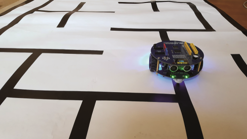
Fig. 10
Ultrasound sensor for Alphabot2
It is a classic ultrasound sensor labeled HC-SR04, ideal to measure the distance of objects placed in front of the robot; besides the indispensable measurements have, it also adds to the look of the robot by making the front look like it has eyes. The sensor is a SONAR (ultrasound rater) and its functioning is synthesized in Fig.11, where you can see the ultrasonic waves starting from the left capsule and those reflected by the object encountered coming back on the right capsule.

Fig. 11
Two distant lines (pins 2 and 3 of Arduino) take care of controlling the sensor, one is used to generate the ultrasound signal (TRIG) and the other one is used to measure the delay of the reflected signal (ECHO), through which the distance from the object is determined (it counts the time on the way out and back and, since the sound speed is known, it calculates the distance travelled).
We can test the ultrasound sensor using the Ultrasonic_Ranging.ino’s catch by reading values provided by the sensor directly on the serial monitor of Arduino, by setting a communication speed of 115 kbps. The program section allowing to detect a distance is reported in List 2 and it shows the function for measuring the distance using the ultrasound sensor. Waveshare provides the example called Ultrasonic-Obstacle-Avoidance.ino in which the ultrasound sensor is used to detect the presence of obstacles when the robot is moving, in which case it carries out an evasive maneuver that makes the robot turn and then moves it forward in a different direction.
List2
int Distance_test() // Measure the distance
{
digitalWrite(TRIG, LOW); // set trig pin low 2μs
delayMicroseconds(2);
digitalWrite(TRIG, HIGH); // set trig pin 10μs , at last 10us
delayMicroseconds(10);
digitalWrite(TRIG, LOW); // set trig pin low
float Fdistance = pulseIn(ECHO, HIGH); // Read echo pin high level time(us)
Fdistance= Fdistance/58; //centimeter
return (int)Fdistance;
}
Infrared obstacle sensors for Alphabot2
On the front side of the robot we have to obstacle sensors with infrared technology since they are positioned slightly facing the sides of the robot, it will be possible to detect any obstacles in their position in relation to the robot, i.e. more on the left or on the right of it.
These sensors do not provide distance from the object but they only detect its presence, in fact, their output is a digital one (ON/OFF) and it is read through the expander I/O module. Sensitivity, which is the distance at which the sensors activate, can be defined by acting on the two small light blue trimmers placed on the bottom of the robot. Still on the front side, next to the two sensors, there are two small LEDs which light on when the sensors detect an object, by making them easier to calibrate.
On a software level, we can find the Infrared-Obstacle-Avoidance.ino example which function is similar to the previous example; if needed, you can adjust the value in line int Speed = 120 in order to add it the robots moving speed, which might be too fast. On a software level, the status of the two sensors is read by sending a query to the PCF8574 integrated to which the sensors are connected; we use functions PCF8574Write() and PCF8574Read() to interact with the integrated circuit. In the Infrared-Obstacle-Avoidance.ino sketch, the lines allowing to read the value of the sensors are the following:
PCF8574Write(0xC0 | PCF8574Read());
value = PCF8574Read() | 0x3F;
Value is equal to 255 if no sensor encounters an obstacle while its value is lower if even just one of the sensors detects an obstacle.
We can use both types of sensors at the same time, in this case, you can take the example named Ultrasionc-Infrared-Obstacle-Avoidance.ino as a programming reference since it takes advantage of both sensors to make the robot move forward avoiding the obstacles. If you want to test these sketches, you can simply let the robot roam in your house, it will autonomously avoid crashing into furnishers, doors and more.
Onboard LEDs
Alphabot is equipped with four programmable serial RGB LEDs with just the data line connected to pin 7 of Arduino. The necessary library to manage the communication is called Adafruit_NeoPixel and the example’s catch is called WS2812.ino. The library provides some simple commands allowing to very easily write a program. The first necessary line is the one related to the library initialization using the instruction Adafruit_NeoPixel:
RGB=Adafruit_NeoPixel(4, PIN, NEO_GRB + NEO_KHZ800)
To specify the pin used for communication, the number of LEDs available and the handling mode. In the Setup section of this sketch, you must initialize the LEDs using the instruction RGB.begin(). To set a color value on one of the LEDs, you can use the instruction:
RGB.setPixelColor(LEDs, RGB.Color(valueR, valueG, valueB))
Specifying which LED in which color using RGB values. In order to specify the brightness level, you can use the instruction RGB.setBrightness(0), while you can use the instruction RGB.show() to activate the LEDs.
Below you can find a segment of code used to light the four LEDs using different colors, remember that once programmed, the LEDs will keep lighting on based on the last command received; therefore, if we want to turn them off completely, we will need to turn all the RGB values to zero or set brightness to zero:
RGB.begin();
RGB.setPixelColor(0, RGB.Color(255, 0, 0));
RGB.setPixelColor(1, RGB.Color(0, 255, 0));
RGB.setPixelColor(2, RGB.Color(0, 0, 255));
RGB.setPixelColor(3, RGB.Color(255, 255, 0));
RGB.show();
Since they are all facing down, these LEDs allow having a colored halo around the robot for a striking visual impact.
OLED display
Equipping the robot with a low consumption OLED display was the “a cherry on top”; it is very easy for displaying any kind of information and, combined with the joystick, it allows to implement a menu-based interface to manage the functioning parameters of the program.
For its functioning, we have to install libraries Adafruit_GFX and Adafruit_SSD1306, besides the Wire system library. Libraries take care of managing the command signals at the low level, leaving only the graphical management to the programmer; for space reasons, we are not reporting all the available comments, which are already well described in the sketch named oled.ino. There are comments available to write text in various fonts and geometric elements such as lines, circles, squares (even with rounded corners) and triangles.

Fig. 12
JOYSTICK
Really useful as an input device instead of bulky buttons, it allows, for instance, to set a number of values or launch certain functionalities implemented in the software.
It is a digital joystick, which means it is composed of a series of switches which close according to how we are going to move the central pivot, in a similar way of what was implemented in mobile phones some generations ago, e.g. the Nokia N70. By using sketch joystick.ino we could command the motor rotation via the joystick. This firmware is more complex than the previous ones, just for the fact that it has to implement the control using the I²C protocol of the PCF8574 integrated circuit with, to which the joysticks terminals are connected.
Luckily, the only code lines we have to take care off are basically those make an inquiry to the PCF8574 integrated into verifying in which position the joystick is, as reported in List 3, showing the sketch.
List3
PCF8574Write(0x1F | PCF8574Read());
value = PCF8574Read() | 0xE0;
if(value != 0xFF)
{
switch(value)
{
case 0xFE:
Serial.println(“up”);break;
case 0xFD:
Serial.println(“right”); break;
case 0xFB:
Serial.println(“left”);break;
case 0xF7:
Serial.println(“down”);break;
case 0xEF:
Serial.println(“center”);break;
default :
Serial.println(“unknow\n”);
}
Buzzer
Among the onboard peripherals of Alphabot2 there is a buzzer (to be specific, it is a piezo-buzzer with an integrated oscillator) capable of emitting only one musical note (the classic beep) whenever it is powered on. It is controlled through a digital line connected to the integrated used as I/O expansion; on a firmware level, only two functions are needed:
#define beep_on PCF8574Write(0xDF & PCF8574Read())
#define beep_off
PCF8574Write(0x20 |
PCF8574Read())
in the sketch, all you have to do is we call these functions to play the beep (bepp_on) or to turn it off (boop_off); you can find a practical example in the sketch named Joystick.ino.
Remote control
In the kit you will also find a small IR remote control equipped with 21 membrane keys that you can use to interact with Alphabot, the corresponding IR receiver is placed next to the right wheel. The sketch named IR.ino contains all the instructions to command the movement of the robot using the remote control, keys 2 and 8 are used to control the movement forward and back door, while keys 4 and 6 are used to make the robust turn. Volume + e Volume – allow modifying the robot’s movement speed.
The main functions implemented in the sketch IR.ino are IR_decode(), used to determine the code of the press key, and function translateIR() executing the command associated to the specific code received.
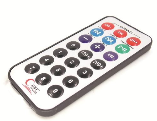
Fig. 13
Bluetooth control for Alphabot2
This is an optional functionality that needs a transmitter unit (such as a smartphone) and a Bluetooth module compatible with Xbee pin layout, both of which you can see in Fig. 14, where the arrow indicates the socket to insert the device in the upper board of Alphabot2.
Anyway, you can’t reprogram the module with AT commands to customize its functioning.
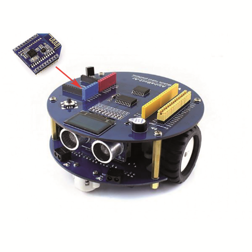
Fig. 14
The module takes advantage of the hardware serial to communicate using lines D0 and D1, already used by the USB/serial converter of Arduino, therefore we have to remove the Bluetooth module before being able to program the robot.
The app suggested by Waveshare to manage communication can be downloaded from the website of the manufacturer at www.waveshare.com/wiki/Dual-mode_Bluetooth, there is a version both for Android and iOS. On the manufacturer’s website, you can also find all the information for the advanced use of the Bluetooth module. Fig. 15 shows how it looks like on the smartphone’s display, in the Android version.
Being a dual-mode Bluetooth module, by activating the device search from the Bluetooth menu of your smartphone, you will find two names: Waveshare_BLE and Waveshare_EDR; this means the module allows to be used both as BLE module (version 4.0) but also as BR/EDR module (version 2.0) therefore ensuring compatibility with third-party apps, generally started to work with the HC-05 module or similar.

Fig. 15
Conclusions
Well, this ends our description of Alphabot 2, a new robotics kit that, in our opinion, is a very rich product from a hardware perspective which surely would not let you down.
The vast documentation and the software demos provided by Waveshare offer all the necessary information to use it, both for base tasks and for whoever wants to (and we certainly hope so) customize their projects with additional features. So, we hope you’ll enjoy your new Alphabot 2 robot on wheels.
From openstore
