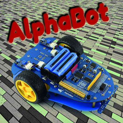
A robotics development platform based on a two-wheel mechanics plus pivoting wheel on which you can prototype applications, controllable with popular Arduino Uno, Raspberry Pi 3 boards or both.
Robotics is one of the most engaging parts of electronics because it can combine different fields of knowledge and skills in the same project; in fact, creating a robot requires notions of electronics, mechanics, programming as well as mathematics and physics. This is why we think it is useful to propose, whenever possible, themed projects, especially autonomous robots capable of moving on the ground using wheels, which already require mechanicals knowledge in order to design the movement system, electronics knowledge both for controlling mortars and for handling the sensors, as well as computer programming to develop algorithms for move-in, avoiding obstacles, receiving comments etc. Alphabot, the robot described here, is a development platform that already sold some aspects, allowing us to focus on programming and control; this is why we have selected it for you. Alphabot is a two-wheeled robot plus one pivoting wheel (a ball-caster, actually) on which you can develop many robotics applications; it’s “brain” can be Arduino Uno, Raspberry Pi 3 or both. It includes dual board support sense, for more demanding applications, it allows to distribute tasks and give the most difficult to Raspberry Pi (managing the camera and the RF wireless links) while Arduino can take care of the interface with everything else.
[bctt tweet=”An #opensource Robot with #ArduinoUno and Raspberry Pi 3 ” username=”OpenElectronics”]
Composition of alphabot
The platform is composed of two main parts:
- Acrylic base;
- PCB base.
The acrylic base (Fig. 1) is composed of a light blue Plexiglas panel, which the main goal is to support the mechanical parts (side wheels and motor reducers, plus the ball-caster shown in the details of Fig. 1) and the spacers are shown in Fig. 2, found on the opposite side and allowing to mount it on the PCB basis; on the left of the frame, in the same Fig. 2, you can notice the screws used to mount the ball-caster on the opposite side. The ball-caster is a fundamental element of this robot category: whether it is an actual wheel or a ball-caster, it provides stability to the robot by keeping it horizontal in relation to the ground and allowing it to turn.
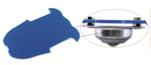
Fig. 1

Fig. 2
The PCB base acts both as mechanical supports for the motor reducers (Fig. 3) on which the wheels are mounted, and for the electronics section of the robot with the drivers for the motors, the voltage reducer for the power supply, the sensor connectors etc. The PCB base includes holes for the fastening the screws to the spacers of the acrylic base.
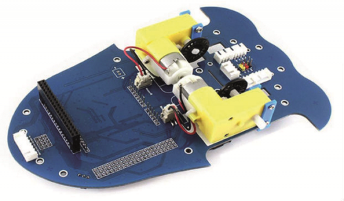
Fig. 3
PCB base
It is a double-sided printed circuit which includes connectors and components on both sides; it hosts and interconnects Arduino and/or Raspberry Pi, as shown in Fig. 4.
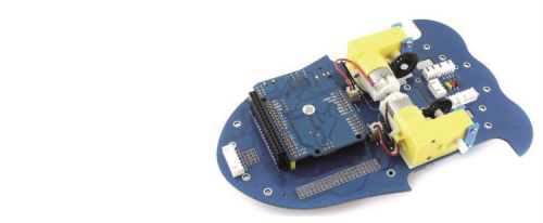
Fig. 4
Let’s analyze in detail Fig. 5, where the various parts have been assigned a number in order to identify them better. Let’s start from the Raspberry Pi interface (1) which is composed of the 40-pin (20+20) connector 40 which we’re used to since the first Raspberry Pi Model B and B+, up to the current version, Raspberry Pi 3. The Arduino interface (2) at the same time is in the standard form factor for Arduino Uno, with this two series of 8+10 pins on the right side of the board, digital pins D0-D13, and pins 6+8 on the left side, the analogue pins A0-A5 and the power pins.
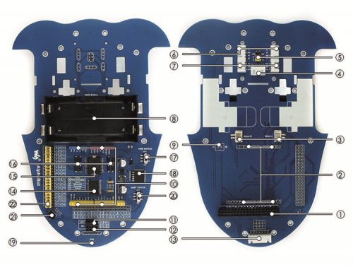
Fig. 5
The motor connectors (3) are used to connect the motor reducers to the AlphaBot base and are both composed of two pins (Fig. 6); both connectors have one-way orientation and are placed in a symmetrical way because the motors will have to rotate in opposite directions; this way, we won’t have to worry about giving inverted commands to the motors, but only to make them move in our desired direction.

Fig. 6
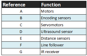
We can equip the robot with additional modules for which we have dedicated interfaces available, each composed of a connector, among which we can find the interface for the ultrasound module (4) shown in Fig. 7 with four pins or the interface for servomotors (5) with six pins, three pins for each servomotor, destined to hobbyist use (0÷180°) to add the pan/tilt to the robot for the ultrasound module or for the camera connected to the Raspberry Pi 3.

Fig. 7
Other preset interfaces are the double interface for the IR obstacle detection sensor (6), just like the two, 4-pin sensors (Fig. 8) that we can use to detect obstacles while the robot is moving. The optical encoders mounted next to the wheels (Fig. 9) are also equipped with their localizable connection in Fig. 5 as 3-pin encoder interface (7); we can use the encoders for two control speed of each wheel and correct the trajectory via software. This is possible if the motor reducers are equipped with a rotational encoder (see below).

Fig. 8

Fig. 9
Let’s move on to the last of the available connections on the PCB base with the UART interface (11) aimed to the direct connection of an HC-05- or HC-06-type Bluetooth module (not included in the base kit) with which we can develop a remote control system for a smartphone or any other devices (Fig. 10) compatible with such technology.

Fig. 10
The SPI interface (12) fits RF wireless module NRF24L01 and we can build the remote control using another Arduino Uno equipped with the same receiver NRF24L01 (Fig. 11) which can use to give movement controls and receive information from the sensors. The 7-pin connector on the side where the motors’ positions are printed, is used to connect the line follower interface (13) to the dedicated connector, included in the Alphabot base kit (Fig. 12); we can draw the path using a black line on a white background and program the robot to closely follow it.

Fig. 11
On the PCB days, besides the interfaces we have just seen, there is the electronics section dedicated to the power supply composed of the battery case (8) where we can place to 3.7 V 18650 Lipo button batteries which provide energy to the whole system. Notice how the battery case was placed so that it is in a central position, corresponding to the motors which represent the other major weight factor. This placement keeps the robot’s centre of gravity near the half of the PCB, granting a higher stability.
Next, to the battery case, we can find the external power pins (not soldered, detail 9), you can power the circuit using this to pins at 7.4 V giving up the batteries in their weight.
We end the description of the robot’s power section with the power switch (17) used to turn the robot on and off, whether powered by the batteries or through an external connector.
The LM2596 (18) had to be here to guarantee the right power to Arduino and Raspberry Pi (5V), considering that the batteries provided 7.4 V. Finally, the power indicator (19), the LTE indicating power voltage and therefore that the robot is on.
The PCB base is equipped with an Arduino expansion header, i.e. the connectors of Arduino UNO, used to expand the functions of the robot with the Arduino shields.
The motor control is entrusted to the LM298P (15) double H-bridge, equipped with the unfailing anti-inversion diodes (16) protecting the LM298P from kickback currents of the motors. Next, to the LM298P, we can find the TLC1543 (14) which is a 10-bit Analog to Digital Converter (ADC): this is used only by Raspberry Pi since it doesn’t have a built-in one like Arduino.
On the PCB base, we can also find the IR receiver (21) that we will use to send out direction commands or to start specific preprogrammed routines: following a line or using the distance sensors to avoid obstacles. The sensor works in combination with the infrared remote control (IR) included in the base kit.
We conclude with the Raspberry Pi/Arduino selector (described later) composed of a series of 21 yellow bridges (22) and the UART switch (20).

Fig. 12
PCB base circuit diagram
Let’s now take a look at the circuit diagram of the Alphabot by analyzing its blocks, and we start from the power supply (Fig. 13); we notice that the power coming from the battery and the one coming from the external connector are connected in parallel. This configuration makes the contemporary power supply from the 18650 Lipo batteries and the external source not available because one would go on the other.

Fig. 13
The microswitch interrupts the power supply. The LM2596 integrated is a switching step-down regulator that gets the 5 V needed for the power of all the robot’s components. LED1 is powered through a 1 kohm R1 resistor.
The circuit diagram of the motor control is taken care of by the L298P (Fig.14) which receives signals IN1, IN2, IN3, IN4, ENA and ENB as inputs by the microcontroller and sends out OUT1, OUT2, OUT3 and OUT4 as outputs towards the motors. Inputs IN1, IN2 and ENA control Motor A while inputs IN3, IN4 and ENB control Motor B. Diodes D1÷D8 protect the driver from kickback currents of the motors during rotation inversions.
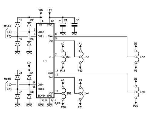
Fig.14
The L298P drivers is powered on pin 12 by the 5 V coming from the LM2596 and it uses the power from Vin pin to power the motors.
TLC1543 is the 10-bit ADC with SP1 serial interface and 11 channels (A0÷A10) shown in Fig. 15 together with the group of distance sensors: the first 5 (A0÷A4) are connected to Header 7 used for the line-follower. The input voltage for the TLC1543 pins ranges between -0,3 and +0,3V compared to the Vcc which is 5 V in this configuration. TA10 input is connected to a voltage divider composed of R4 and R5 (both 10 kohm) which, starting from Vin (7,4V) brings the voltage on pin A10 of T1 at 3.7 V. Pins TA8 and TA9 are used to detect analogue signals coming from the IR distance sensors. The remainder of the diagram shows the interface connections (Fig. 16) with the sensors.

Fig.15
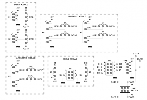
Fig.16
Mounting the robot
The electronics section of Alphabot is already mounted, therefore we will only focus on the mechanical parts and on connecting the sensors to the PCB base. Mount the motors on the PCB base following the printed instructions and place the two motor reducers by screwing them on the provided Plexiglas mounts. Before placing and screwing each motor reducer you have to insert the black wheel, as shown in Fig. 17. Then, connect each motor reducer to its 2-pin interface connector.

Fig.17
The base kit contains the IR distance sensors that you are going to mount using the M3 screw, the plastic nuts (black) and the chrome M3 nuts (Fig. 18); the former will act as spacers between the PCB base and the sensor. Connect the sensors to the PCB base using the 4-wire cables with one-way orientation both on the sensors side and on the AlphaBot side. You will notice that the connectors must start from the sensors, passing through the prepared hole in the PCB and connect to their place on the opposite side. To the connectors shown in Fig. 19 you will connect the optical sensors for reading the perforated wheel mounted in front of the rubber wheel and place on the internal side of the motor reducer; the encoder will then be composed of the perforated wheel and a fork optical sensor (open photocouplers) for each wheel. The Arduino pins involved are D2 for CNTL and D3 for CNTR.

Fig. 18

Fig. 19
On the PCB base, we can find two snap-on sockets with the dual function of mechanical support and be positioning for the sensors on the perforated wheel. Those sensors can be connected using tripolar cables, running them through the groove from which you have previously run the four-poles connector of the distance sensors.
Let’s move on to the last sensors included in the base kit: the line followers, which are provided along with the necessary hardware to install them (Fig. 20). Screw the two spacers on the sensor and connect the 7-pole cable with one-way orientation; use the remaining two screws to fasten the sensor on the PCB base. Fig. 21 shows the mounting and how to pass the cables.

Fig. 20
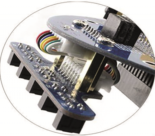
Fig. 21
Let’s move on to mounting the ball-caster on the acrylic base: set aside the PCB base and take the Plexiglas one, two 15 mm M3 screws, four M3 chrome nuts and the metal wheel you can find inside the kit; place 2 nuts on the lower side of the pivoting wheel aligning them with the holes and insert the screws from the bottom up, you will use at least 2 nuts as spacers for the acrylic base of the robot. Pass the protruding screws through the Plexiglas base and fasten the wheel using the remaining 2 nuts. Our advice is to fasten the 2 nuts on the pivoting wheel and act with pliers or a wrench to tighten the remaining nuts after mouthing them on the Plexiglas base. Finally, mount the six spacers on the Plexiglas base using as many screws in the opposite direction related to the ball-caster. You will use the longer spacers you can find in the box you will need them to mount the practical space on the PCB base of the robot.
Since, in this article, we are referring to the use with Arduino, will then proceed by inserting the Arduino Uno board on the same side of the motor reducers, as shown in Fig. 22. The installation is made easier by the position of the connectors which have the typical form factor of Arduino.
End the assembly of the robot by inserting the six screws on the PCB side, the rubber wheels and the batteries.
The only sensors that need calibration are the optical distance sensors, which have a regulation trimmer determining the passage threshold from a high value to a low value on the DOUT pin on sensor and you can use it to define a minimum distance at which the robot must perform an action, for instance turning to avoid an obstacle. The advantage of having a digital signal as output in addition to an analog signal is dual: on one hand, you can decide to ignore the analog value and use the digital value only to control the position of your robot; on the other hand, you can define the threshold at which you carry out an operation by evaluating the digital signal and intervene in a punctual and detailed manner, for instance during a maneuver, thanks to the analog signal to evaluate your movements.

Fig. 21
The Raspberry Pi/Arduino SELECTOR
Alphabot is equipped with a selector that allows assigning the use of all functions of the PCB base to Arduino or Raspberry Pi 3; this selector is composed of a series of 21 yellow bridges, divided by serigraphy (Fig. 23) in seven groups (from A two G) and each one is assigned a function or specific component of the robot.

Fig. 23
The jumpers connecting the pins of the visual boards are shown in Fig. 24. Table 1 describes groups and the assigned functions. Let’s start with group A: the motors are the 6 pins dedicated to controlling the motors and, taking Fig. 16 as a reference, corresponding to IN1, IN2, ENA for the first motor and to IN3, IN4, ENB for the second one.
Table1
Each one of the 6 pins goes to Group A of the selector. Since we are interested in Arduino, we must move the jumpers to the left. Notice that the pins corresponding to the functions (motors, IR etc.) are predefined; this is not a limitation but an advantage since we don’t have to waste time to find the pins and making sure there are no conflicts. Table 2 reports functions S1 and S2, correlated to the two servomotors; as we know, they must be PWM-controlled (Pulse With Modulation) through just one signal pin (S); the other two connection pins of the servomotors are dedicated to power.
Table2

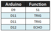
In Table 3 you can find the pins concerning the ultrasound sensor with which you, we can detect the presence of objects and obstacles. Connecting the SR04 sensor requires two pins, one from TRIG and one from ECHO, which can be connected to pins D11 and D12 of Arduino, respectively; in the same table we can see the definition of the pins and the functions relating to the two optical distance sensors, for which we have the possibility to use both an analog signal, which is proportional to the detected distance from the obstacle, and a digital signals proportional to the calibration we have made using the potentiometer at a preset distance.
Table3
Analogue functions are defined on the pins preceded by letter “A”, while the digital functions are defined by pins preceded by letter “D”; letters “L” and “R” are Left and Right respectively, referred to each sensor. For Arduino, we can use the ADC of the microcontroller referred to pins A4 and A5; the digital pins will be D7 and D8 (see Table 4).

Table 5 refers to the interfacing with the line follower sensor; we remind you that the task of reading the signals coming from the five optical sensors mounted on the detection bar is given to the TLC1543, which interfaces with the infrared sensors and communicates with the selected the microcontroller via SPI.
Table5

The robot can be remote-controlled thanks to the IR receiver which can already be found on the PCB base; the related closed bridge on Arduino sends out the correspondence signal on pin D4 (IR function).
You surely have noticed that some pins of the jumpers in Fig. 24 can be used assigning them to different functions: for instance, pin CS is also used as ECHO and pin D10 of Arduino can be assigned both to the CS and to the control of the second servomotor (S2). This choice was made with the possibility of having two boards at the same time, to divide the functions between the two.
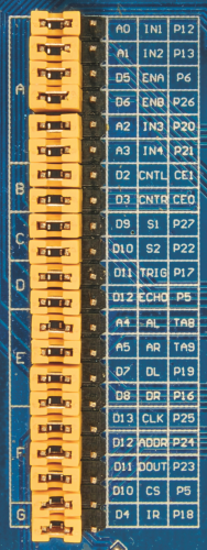
Fig. 24
The firmware
Several code examples are provided along with AlphaBot, some being tests for sensors and electronics and mechanical parts such as the motors; some others are complete base sketches for starting to develop your robot. List 1 reports the code for testing the system. In order to operate, it uses the AlphaBot library, which can be downloaded from the official website of AlphaBot. The instruction:
#include “AlphaBot.h”
includes the library into the sketch. The instance we are going to use to send out commands through the sketch is Car1 and the method used by the sketch are: SetSpeed(speed), Forward(time), Brake(), Backward(time), Left(time), Right(time), LeftCircle(time), RightCircle(time), MotorRun(leftSpeed,rightSpeed).
List1
/***************************************
Waveshare AlphaBot Car Run Test
CN: www.waveshare.net/wiki/AlphaBot
EN: www.waveshare.com/wiki/AlphaBot
****************************************/
#include “AlphaBot.h”
AlphaBot Car1 = AlphaBot();
void setup() {
Car1.SetSpeed(250); //Speed:0 - 255
}
void loop() {
delay(1000);
Car1.Forward(1000); //Car run forward for 1s
Car1.Brake();
// delay(1000);
// Car1.Backward(1000); //Car run backward for 1s
// Car1.Brake();
// delay(1000);
// Car1.Left(1000); //Car turn left for 1s
// Car1.Brake();
// delay(1000);
// Car1.Right(1000); //Car turn right for 1s
// Car1.Brake();
// delay(1000);
// Car1.LeftCircle(1000); //Car left circle for 1s
// Car1.Brake();
// delay(1000);
// Car1.RightCircle(1000); //Car right circle for 1s
// Car1.Brake();
// delay(1000);
// Car1.MotorRun(250,250); //Car run forward for 1s; left motor speed:250,right motor speed:250
// delay(1000);
// Car1.Brake();
// delay(1000);
// Car1.MotorRun(-250,-250); //Car run backward for 1s; left motor speed:250,right motor speed:250
// delay(1000);
// Car1.Brake();
// delay(1000);
// Car1.MotorRun(0,250); //Car left circle for 1s; left motor speed:0,right motor speed:250
// delay(1000);
// Car1.Brake();
// delay(1000);
// Car1.MotorRun(250,0); //Car turn right for 1s; left motor speed:250,right motor speed:0
// delay(1000);
// Car1.Brake();
}
Almost all the loop() section in List 1 is commented (therefore not executable), save from the first lines and therefore the first commands; you can remove the comments from the following lines (thus making them executable) to try out all the methods listed, many of which require just one “time” parameter expressed in milliseconds, instructing the method on how long it will have to be on execution. For instance, Forward(1000) instruct the robot to proceed for 1 second forward. The speed used to move has been set in setup() where using method SetSpeed(250) we have set the value of PWM sent on pins D5 and D6 to 250.
All the methods accepting the parameter“time” (Forward, Backward, Left, Right, LeftCircle, RightCircle) present the same functioning method of the Forward method used in the first lines of function loop(); they just execute different movements.
The method MotorRun calls for receiving two-speed values: the first one for the left motor and the second one for the right motor; expected values for this method are 255 both positive and negative. If we take a look at line 48 on the list, we can notice that the values (from -1 to -255) make the robot go backwards. Moreover, we can notice that after using method MotorRun a 1000 ms time is indicated, which is 1 second, not used in case of methods such as “RightCircle” which require “time” as argument: this information let us understand how this method is limited to signaling the motors with the rotation direction and power (PWM) to apply without defining the execution time of the movement, therefore if we do not specify any delay() after MotorRun, Alpharobot would stay stationary in its starting position and would execute the next command without giving feedback it has received the MotorRun command. Actually, the command worked but we didn’t give the robot enough time to execute it and therefore we see no results. If we wanted to control the motors without using the provided library, we would need to know how to set the digital signals on pins IN1, IN2, IN3 ed IN4. To do that, we can make use of Table 6, which we have extracted from the official documentation from the manufacturer indicating the possible combinations correlated to the movements that we want the robot to execute. In the first sequence, pins set to “1” set the direct action of the two motors on the same side. We know that the motors of the robot when positioned as in our case, must be rotated in opposite directions in order to obtain a movement along a straight line. Same goes for the second line in which pins set to “1” are the two central ones and guarantee the opposite rotational movement of the motors which will cause the robot to move on a straight line but in the opposite direction compared to the movement from the first line.
The third line of Table 6 allows us to set the movement of just the right motor while keeping the left motor stationary. The effect will be the robot rotating in the opposite direction: left.
Table 6
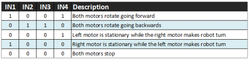
The fourth line inverts the motors movement, determining the rotation of just the left motor and the consequent circular movement of the robot to the right. The last line stops all the motors and consequently, it stops the robot. Of course, these settings for rotating the motors are not enough to impose rotation and make the robot move, we also have to set pins Ena and Enb with a certain speed using the signal PWM.
Finally, notice that all the methods without an execution time, such as MotorRun, are followed by a delay time to allow the robot to execute a movement before instructing it with a second command.
You probably have noticed that the left or right rotation of the robot is executed by making just one motor turn; the trajectory will be as shown in Fig. 25, where the stationary wheel acts as a pivot during rotation. However, we can decide not to leave one of the two wheels stationary and make them turn in the opposite direction at the same speed by setting, for instance, the two sequences for IN1, IN2, IN3 and IN4 (Table 7).
Table 7

By changing the rotation speed of the right wheel compared to the left wheel we will obtain different trajectories and curved lines.

Fig 25
In order to control the motors using the information above, you can use the code shown in List 2, which allows us to carry out a rotation test for both motors using the information contained in the tables above. Specifically, the first clients define the correlation between the name found in tables 3 and 4 and the actual pins used to control Alphabot from Arduino. Next, the setup() function sets all pins to 0, including pins ENA and ENB so that when the robot starts moving, even for a few milliseconds, it receives a stop signal both on the control pins IN1-4 and on ENA and ENB. The loop() function sets pins IN1-4 according to the sequence found in the first line of Table 7 which, according to the manufacturer’s specifics, it makes the robot go straight on ( Forward). Finally, it sets the motor rotation to a slightly lower value than the possible half for motors (PWM = 100 ).
List2
#define IN1 A0
#define IN2 A1
#define IN3 A2
#define IN4 A3
#define ENA 5
#define ENB 6
void setup() {
Serial.begin( 9600 );
pinMode( IN1,OUTPUT );
pinMode( IN2,OUTPUT );
pinMode( IN3,OUTPUT );
pinMode( IN4,OUTPUT );
pinMode( ENA,OUTPUT );
pinMode( ENB,OUTPUT );
digitalWrite( IN1,0 );
digitalWrite( IN2,0 );
digitalWrite( IN3,0 );
digitalWrite( IN4,0 );
analogWrite( ENA,0 );
analogWrite( ENB,0 );
Serial.println( “Setup Scuccessfully” );
}
void loop() {
digitalWrite( IN1,1 );
digitalWrite( IN2,0 );
digitalWrite( IN3,0 );
digitalWrite( IN4,1 );
analogWrite( ENA,100 );
analogWrite( ENB,100 );
}
You can try all the possible rotation combination of the two motors simply by varying the first four lines of loop() replacing values with sequence 0 and 1 found in tables 4 and 5. Remember to reload the sketch every time you make a change.
List 3 is one example we use to verify the functioning of the optical distance sensors included in the base kit. Each sensor has two kinds of signals we can use to avoid obstacles during the movement, an analogue signal and a digital one. In order to use the digital signal we have to first make a calibration that you can carry out by following the instructions in the box “optical sensor calibration”. List 3 sets in the first four lines, the correspondence between the pins where the sensors of signals arrive, the corresponding pin number on Arduino and constants defined with the syntax:
PH: photo
A/D: segnale analogico (A) o digitale (D)
L/R: sinistro (Left, L) o destro (Right, R)
This lets us understand that pin A4 is the one connected to the left sensor on the analogue, proportional signal.
The setup() function only sets all the pins to INPUT coming from the sensors and loop() writes the values read from each sensor on the serial monitor, both on the analogue and on the digital pins.
List3
#define PHAL A4
#define PHAR A5
#define PHDL 7
#define PHDR 8
void setup() {
Serial.begin( 9600 );
pinMode( PHAL,INPUT );
pinMode( PHAR,INPUT );
pinMode( PHDL,INPUT );
pinMode( PHDR,INPUT );
Serial.println( “Setup Scuccessfully” );
}
void loop() {
Serial.print(“Left: “);
Serial.print( analogRead(PHAL) );
Serial.print(“ :-: “);
Serial.print( digitalRead(PHDL) );
Serial.print(“ Right: “);
Serial.print( analogRead(PHAR) );
Serial.print(“ :-: “);
Serial.print( digitalRead(PHDR) );
Serial.print( “\n” );
}
It is a simple sketch allowing to read, test and calibrate each sensor. By reading the values, we can understand how the sensors react to the presence of an obstacle in front of them. To this regard, we must notice that the optical sensors are sensitive to environmental light variations and to reflective surfaces, in fact, if we try to put an obstacle with a white background in front of them and one with a black background, we can notice the difference in the values returned and analog mode, by leaving the two obstacles distance unchanged. Besides, since they are lighted by a LED, this lighting varies when the lighting source of the robot varies, e.g. if you power the robot only using the Arduino’s USP, the sensors will return a different value compared to a power supply coming from the 18650 batteries equipped on the robot. We suggest to carry out all the measurements and calibrations with full charge batteries and the switch set to “on”.
List 4 shows a simple way to use the proximity sensors or optical distance sensors in order to detect obstacles in front of the robot or to follow them. The ProximityConfig() function only works to set pins D7 and D8 as INPUT to which the sensors digital pins are connected, which you have previously calibrated. The loop() cycle reached signal on to sensors and evaluates if there is a HIGH signal on either, which means if the sensor has an obstacle in front of it. Under normal conditions, if no sensor detects an obstacle, both sensors return LOW (value 0) and the robot moves forward. If the right sensor detects an obstacle, the robot executes the Right() method. If the right sensor detects an obstacle, the robot executes Left() mode. If both detect an obstacle, case else, the robot stops.
List4
/***************************************
Waveshare AlphaBot Car Infrared Tracking Objects
CN: www.waveshare.net/wiki/AlphaBot
EN: www.waveshare.com/wiki/AlphaBot
****************************************/
#include “AlphaBot.h”
int LSensorPin = 7;
int RSensorPin = 8;
int LSensor;
int RSensor;
AlphaBot Car1 = AlphaBot();
void ProximityConfig() {
pinMode(RSensorPin, INPUT);
pinMode(LSensorPin, INPUT);
}
void setup() {
ProximityConfig();
Car1.SetSpeed(150);
}
void loop() {
RSensor = digitalRead(RSensorPin);
LSensor = digitalRead(LSensorPin);
if (LSensor == LOW && RSensor == LOW) Car1.Forward();
else if (LSensor == HIGH && RSensor == LOW) Car1.Right();
else if (RSensor == HIGH && LSensor == LOW) Car1.Left();
else Car1.Brake();
}
List 5 represents a variant of List 4 and implements the functionality to allow the robots to do not stop in front of an obstacle; basically, only the else condition is different from the previous list and instruct the robots to go back for 5 ms and then turn left for 5 ms more before reprising the main cycle. This implies that, whenever the robot detects an obstacle in front of both the sensors, even after the manoeuvre, it will execute the manoeuvre again until it will find itself in one of the previous conditions.
List5
/***************************************
Waveshare AlphaBot Car Infrared Obstacle Avoidance
CN: www.waveshare.net/wiki/AlphaBot
EN: www.waveshare.com/wiki/AlphaBot
****************************************/
#include “AlphaBot.h”
int LSensorPin = 7;
int RSensorPin = 8;
int LSensor; //Left Infrared Proximity Sensor signal value
int RSensor; //Right Infrared Proximity Sensor signal value
AlphaBot Car1 = AlphaBot();
void ProximityConfig() {
pinMode(RSensorPin, INPUT); //Define the input pin of Right Infrared Proximity Sensor
pinMode(LSensorPin, INPUT); //Define the input pin of Left Infrared Proximity Sensor
}
void setup() {
ProximityConfig();
Car1.SetSpeed(150);
// Serial.begin(9600);
}
void loop() {
RSensor = digitalRead(RSensorPin); //LOW means signal, HIGH means no signal
LSensor = digitalRead(LSensorPin); //LOW means signal, HIGH means no signal
// Serial.print(“RSensor: “);
// Serial.println(RSensor);
// Serial.print(“LSensor: “);
// Serial.println(LSensor);
if (LSensor == HIGH && RSensor == HIGH) Car1.Forward();
else if (LSensor == HIGH && RSensor == LOW) Car1.Left();
else if (RSensor == HIGH && LSensor == LOW) Car1.Right();
else {
Car1.Backward();
delay(5);
Car1.LeftCircle();
delay(5);
}
}
List 6 allows us to read the encoder mounted on the motors and evaluate the number of revolutions for each wheel. Let’s start with counting the signals; by counting the slots on each wheel, you would find out there are 20 of them, and this tells us that the signals coming from a complete revolution of the motor are 20 x 2 = 40 data both from the passage of light and from the dark section of the encoder wheel. In the first two lines, the list defines the pins to which each encoder is connected, on Arduino Uno pins 2 and 3 support the interrupt reading, which means that status change of the pin can be used to activate a counting function which is independent of the loop() in which value is only used in the loop for the necessary evaluations. Going back to List 6, the following lines are used to define the counters we will use to increment the number of counts and the subsequent number of rotations. In the setup() function we must pay attention to two lines because they use the command attachInterrupt where the first value represents the pin on which we want to activate the interrupted reading, the second value is the function to be recalled and the third one represents the constant use to communicate the attachInterrupt function when to call the function defined in the second value. Basically, every time Arduino reads a change (CHANGE) on pins 2 or 3, it will recall functions updateEncoderL o updateEncoderR, respectively, defined after the loop(). The presence of value 0 and 1 instead of the respective 2 and 3 is due to the fact that, under interrupt mode, the pins are defined by a progressive number starting from 0, an Arduino Uno, the interrupt 0 corresponds to pin 2 and interrupt 1 corresponds to pin 3. The loop() function only writes on the serial monitor the values: valEncL, valEncR, giriL, giriR calculated by the subsequent functions. The function updateEncoderL() is recalled every time pin 2 switches from 0 to 1 and vice versa, each time the sensor detects the condition of light passing through the slot or dark corresponding to a full on the encoder wheel. Each time it is recalled, it increments the valEncL’s value by one unit; every 40 values, the if resets valEncL’s value and increments the number of rotations by 1, in fact, a complete rotation of the wheel corresponds to 40 detections of 0 and 1. The function updateEncoderR() executes the same operations for the right wheel. By running this sketch, the serial monitor will display the values of valEncL and valEncR, going from 0 to 40 and every time it reaches the 40th value, the number of rotations for the corresponding wheel is incremented by 1.
List6
#define encL 2
#define encR 3
byte valEncL = 0;
byte valEncR = 0;
long int giriL=0;
long int giriR=0;
void setup() {
Serial.begin( 9600 );
pinMode(encL,INPUT);
pinMode(encR,INPUT);
attachInterrupt(0, updateEncoderL, CHANGE);
attachInterrupt(1, updateEncoderR, CHANGE);
}
void loop() {
Serial.print( valEncL );
Serial.print( “ :-: “ );
Serial.print( valEncR );
Serial.print( “ :-: “ );
Serial.print( giriL );
Serial.print( “ :-: “ );
Serial.print( giriR );
Serial.print( “\n” );
}
void updateEncoderL(){
valEncL++;
if ( valEncL > 40 ) {
valEncL=0;
giriL++;
}
}
void updateEncoderR(){
valEncR++;
if ( valEncR > 40 ) {
valEncR=0;
giriR++;
}
}
Using the encoder is crucial when you want robots to follow a precise directory because you can correct the movement errors due to the different traction of the wheels on the ground that inevitably tends to deviate the robot from a straight line during its movement. With that said, we think we have explained everything. Have fun experimenting!
From openstore
Alphabot robotic platform – kit

[…] Alphabot, THE OPEN SOURCE ROBOTPosted 2 months ago […]