When inserted in the cigar lighter socket, it signals the electrical system’s voltage level by means of a bi-color LED.
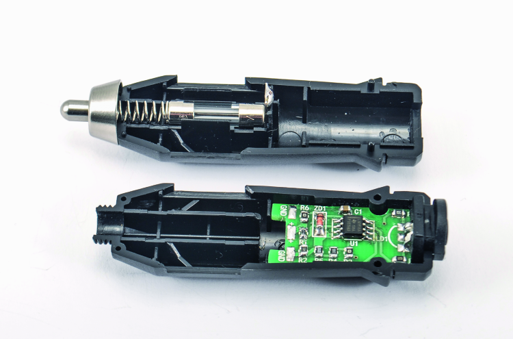
Especially in the cold season, knowing the battery voltage, when the engine is off, allows us to prevent unpleasant inconveniences, such as a failed engine start; in fact the voltage really makes a statement on the accumulator’s conditions, that is to say, on its remaining charge and on the cabability it still has to charge and supply the starting current required by the engines for the start, especially if they are diesel ones (that notoriously require a greater power from the starter, because of the greater compression ratio: from 15:1 of the modern turbodiesel ones to 22:1 of the old aspirated diesels). But the voltage of the car’s electrical system also makes a statement about the running engine, since it allows to understand if the generator (typically, an alternator) is correctly charging or if some problem limits the voltage. For these reasons, to have a voltmeter in the dial – one that indicates such a voltage – is a very useful thing, and this was a shared opinion until a few years ago, when it was found on mid-level and luxury cars; later – in order to save on the manufacturing costs and because of the belief that the voltage could be checked via the engine control unit, by entrusting it with the warning on the dashboard – the voltmeter disappeared. This is the reason why we propose a very simple accessory, that may be created on a printed circuit board that is miniaturized enough to enter a cigar lighter plug, and that is to be kept in the car, so to know, by means of the light created by a bi-color LED, in which condition the battery and the car’s electrical system are. By using a bi-color LED (red/green) we obtain a green signal if the voltage exceeds 12 volts, a yellow one if it is between 10.4 and 12 V and a red one if it is below 10.4 V; therefore the red light warns about a low battery, the yellow one that there is an acceptable voltage and the green one that the battery is well charged.
You will be able to understand the meaning of these voltages by considering that the car’s accumulator is of the lead-acid type, that is to say a reversible electrochemical device, whose elementar structure (cell) is made of two lead plates that are submerged in a liquid, named electrolyte, that is sulphuric acid (H2SO4) diluted in water.
In idle conditions, the battery cell’s voltage is of about 2 V; it grows during the charge and decreases during the discharge (in order to obtain a 12 V accumulator we therefore need to connect six cells in series). If you want to consider the idle voltage at the terminals as an index of the charge level (the battery must have been idle since at least 6 hours and the voltmeter with which to carry out the measurement must have a very low absorption), the full charge voltage is 12.6 V, it goes down to 12.2 V at half charge, and goes below 11.5 V with low battery. Under 10 volts, the battery is not just low, and if it is not soon recharged, the plates will be irremediably corroded by the acid until the battery becomes unserviceable and it cannot be recharged any more.
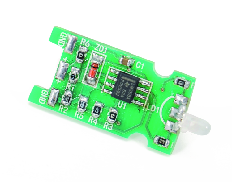
Circuit diagram
Well, having said this, we will see how the circuit that gives us the signal is created: the circuit diagram shows its essentiality, since it is a voltage comparator – whose outputs power the two junctions of a red-green bi-color LED, of the common cathode kind – and that has been configured in order to show a voltage level.
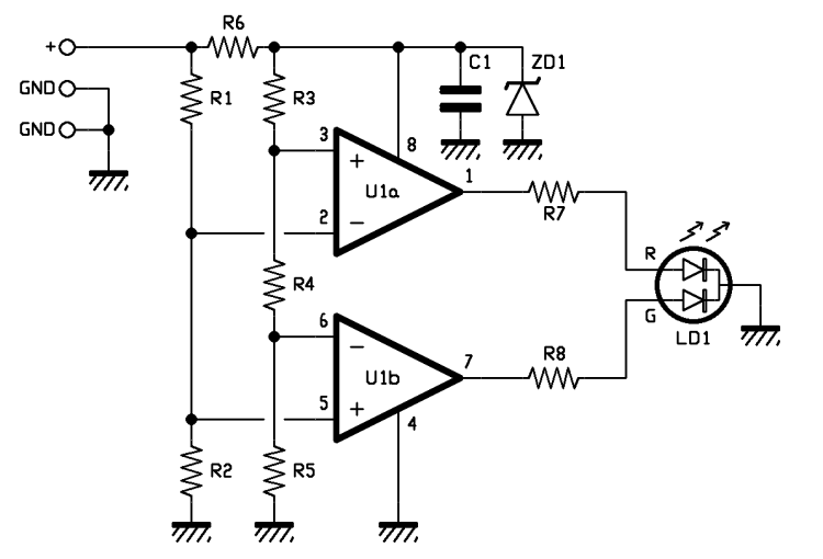
The input voltage of the comparator is directly drawn from the cigar light socket and therefore it is the potential difference found between + and – in the car’s electrical system. On the other hand, the two voltages, applied as a reference to the comparator, are obtained – still starting from the car’s electrical system – by acquiring a stabilized component from it via the 9.1 V Zener diode; having some stabilized voltage references allows to obtain a comparator that works indipendently from the voltage fluctuations of the electrical system. If it weren’t like that, and the references were taken from the supply voltage, without any stabilization carried out, the commutation thresholds of the single comparators would move according to the car’s electrical system and therefore the indication given by the LED would be distorted, since if the battery voltage is increased, even the thresholds grow: therefore it could happen to see a yellow light from the bi-color LED, even if the battery is actually well charged, or to see a green or yellow light when it is not charged.
But let’s go in order and see that the + (connected to the car’s +12V, that is to say the tip of the cigar lighter’s plug) powers both the resistive voltage divider (composed of R1 and R2), and R6, that is the ballast resistor of the Zener diode: the latter ideally stabilizes the voltage at its ends at 9.1 volts, and is filtered by the capacitor, so to avoid that the pulse disturbances found in the car’s electrical system (for example, as the ones created by the starter’s brushes, by the one of the windscreen wiper or by those of the power windows) may alter the comparator’s functioning. With the voltage that has been stabilized by the Zener diode, we power the dual operational amplifier as well, so to obtain a stable operation of the comparators.
The Zener’s voltage powers a multiple resistive voltage divider, that in this specific case is composed of R3, R4 and R5, and that supplies the reference potential to the non-inverting input of the U1a operational amplifier and to the non-inverting one of the U1b; the operational amplifier that has been used is the LM358 (SMD version). We preferred it over classic amplififiers such as, for example, TL082, since it is fitted to work with a single power supply and its output – with a single power supply referred to ground – manages to go down, almost up to zero volts.
The configuration of the operational amplifiers is comparator: in this particular type, the two comparators have consecutive voltage references (that is to say, the ones that decide the commutation threshold of the respective outputs). U1b voltage is supplied by the R5 resistor that acts as a voltage divider, along with the sum of R3 and R4 (in this case we suppose an ideal operational amplifiers therefore impose that they do not draw any current from the outputs), while the one of U1a is given by the sum of R4 and R5, that act as a voltage divider along with R3. As a consequence of this, U1b’s inverting input receives 7.46 V and U1’s non-inverting one is exposed to 9.09 volts; the comparators have the input in common (U1a’s pin 2 is connected along with U1b’s pin 5) and powered by a resistive voltage divider (R1/R2) that receives a voltage from the circuit’s input, that is to say, it reduces the voltage of the car’s electric system by a factor of 0.716. As a consequence of this, the inferior voltage divider (U1b) has the output at zero volts when the circuit’s input voltage is lower than 10.4 V, while in such a condition the superior one (U1a) shows the output at a high level (a bit less than 9 V); therefore with a battery voltage under 10.4 V, only the red light junction of the bi-color LED is turned on. If the voltage is higher, but between 10.4 and 11.6 V, the output of the U1a voltage divider remains at a high level, while U1b – given that now the inverting input is found as less positive of the non-inverting one – goes to a high level and turns on the bi-color LED’s green junction. Since the red light is turned on at the same time, the diode emits a yellow light (two lights, a green and a red one, make a yellow one).
Finally, if the voltage exceeds 12V, which corresponds to exceeding the U1 voltage divider’s commutation threshold, the output of the latter goes to a logical zero (because the inverting input becomes more positive of the non-inverting one) and it turns off the red diode; since the one of the U1b remains at a high level, the bi-color LED shows a green light.

While I assume that C1 is something on the order of a 0.1μF and know the zener to be a 9.1V unit, and it looks as if R3 and R6 are 100Ω, it’s difficult to make out the other resistor values. Verified values for Rs 1 through 8 would be helpful to some of us.
I realize that many of us can do the basic math, but others might not be so enabled or inclined.