- Building a 3D Digital Clock with ArduinoPosted 4 months ago
- Creating a controller for Minecraft with realistic body movements using ArduinoPosted 5 months ago
- Snowflake with ArduinoPosted 5 months ago
- Holographic Christmas TreePosted 5 months ago
- Segstick: Build Your Own Self-Balancing Vehicle in Just 2 Days with ArduinoPosted 6 months ago
- ZSWatch: An Open-Source Smartwatch Project Based on the Zephyr Operating SystemPosted 7 months ago
- What is IoT and which devices to usePosted 7 months ago
- Maker Faire Rome Unveils Thrilling “Padel Smash Future” Pavilion for Sports EnthusiastsPosted 7 months ago
- Make your curtains smartPosted 8 months ago
- Configuring an ESP8266 for Battery PowerPosted 8 months ago
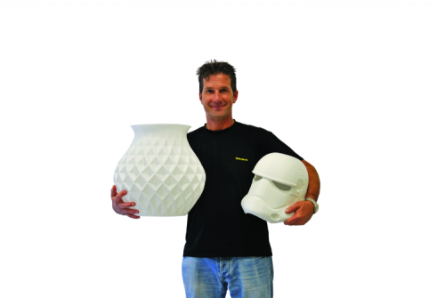
3D4040: The big 3D printer with a small price
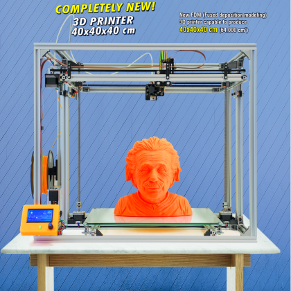
[bctt tweet=”New FDM (Fused deposition modeling) 3D printer capable to produce 40x40x40 cm (64,000 cm3) objects.” username=”OpenElectronics”]
This printer has a building volume of 400 x 400 x 400 mm; it integrates all the functions of the 3Drag, including the “hackability”, that is typical of the Arduino-based controller.
When we created our first 3D printer – that we named 3Drag – we were just starting our experience as designers of FDM (Fused deposition modeling, an additive manufacturing technology) machines. However, the audience appreciated the product very much, and this is still true today. That machine, based on an Arduino controller is a landmark, still today, and it is preferred by makers, hobbyists, and professionals that wish to manufacture models of PLA or ABS.
Out 3Drag is limited to the printing of objects having a maximum size of 200x200x200mm: for some applications (such as, for example, terrain models with buildings), this is not ideal; that’s not a case that in our 3Drag Big project we increased the width, by “stretching out” the 3Drag’s original chassis. But since we wanted to go big, we didn’t stop there and we began thinking at how to obtain a machine, capable of doubling the building volume; the fruit of our labour is the new 3D4040 printer: before it could see the light, it required a long development and many tests at the desk; we will show it in these pages.
From the 3Drag to the 3D4040
Doubling the building volume is not an easy task as you may think: the most intuitive solution would have been the one to double the three axes of the original 3Drag printer; this, however, would not have been possible. In fact, while it is true that in our 3Drag Big project we simply increased the chassis’ base, thus enabling the width to be increased (but without touching depth and height), that was as much as we could do. If we had tried to increase the depth, we would have met different problems, and the limits of the 3Drag’s mechanism, that was born for a printing capacity of 200x200x200 mm: it is not suitable for withstanding the stresses caused by the printing of pieces having a big size; the same could be said for the structure (similar to the gallows) that supported the print head and the activation of the Z-axis.
Moreover, it must be said that if we had followed the philosophy used in order to create the 3Drag, we would have had to use a structure having at least double the size; therefore, with a print bed having a 40 cm side, we would have had an encumbrance of at least 80 cm on each side; the reason is that the 3Drag’s print head only goes up and down. A printhead that is fixed on the horizontal axis implies that the outermost part of the piece has to be moved with respect to the print head (that stays at the machine’s centre) at a distance that is equal to the maximum width on the x-axis, and the same goes for the Y-axis (in depth): such a situation is unacceptable, both for the encumbrance and for the deriving costs and weight.
Moreover, for rigidity reasons (very high mass and inertia), it doesn’t have much sense to have a moving print bed of such a size, and also one made of glass.
For such reasons, we thought about a mechanism with a print head that is fixed on the horizontal axis, whose encumbrance does not exceed the size of the print bed itself by much, and to make the print head on the X and Y axes a mobile one, given that the print head has a reduced mass, so that the inertia (even at the highest printing speed) is not a significant one. In the end, we preferred an approach similar to the one we chose for the 3D Vertex.
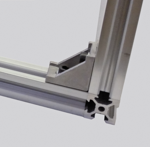
Let’s return to the 3Drag: it must be said that the print bed runs on rectified bars, a solution that is more than adequate for excursions not exceeding 20 cm, but that would have been unworkable for a greater size since there would be unacceptable bendings (the bar’s diameter being equal). Linear guides on rails (for example, such as those of the hiwin, whose features may be checked at the following webpage) have been immediately dropped, because of the very high cost of the guide. The most logical solution is the one to take advantage of the cavities of the bars that have been used when building the chassis and use them as a guide for each axis. For such a reason, the structure of the 3D4040 has been entirely made of aluminium bars (named V-slots) that add a new function, with respect to the traditional T slots; thanks to the V-spline, in fact, they enable the creation of movement systems of the linear kind, that mostly use specific sliding pulleys (V-wheel) that are usually made in POM (Polyoxymethylene) and that are characterized by a long duration and a remarkable accuracy.
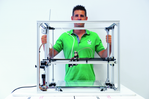
These bars, that we joined by means of die-cast aluminum corner brackets, enabled the creation of a sturdy – yet light and functional (and cheap…) – bearing structure that does not require tie rods or stiffening plates, even though the dimensions of this chassis are respectable ones, reaching 690x630x610 mm.
The Z-axis chassis moves vertically, thanks to two stepper motors that are connected in parallel to the same driver that in turn activate two trapezoidal screws to a stainless steel principles, having a 2 mm pitch; such a subsystem is composed of a frame that enables the movement of the print head on the axes X and Y. In practice, the print head, by means of the Z axis is drawn near or moved away from the print bed, that in our case is attached to the structure.
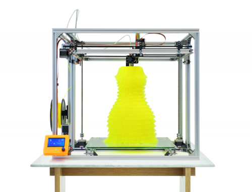
This solution enables a substantial simplification of the chassis, and above all, it makes it possible to keep the barycentre of the whole structure low, which is a very useful thing, given that the print bed (made of a 6 mm thick tempered glass) weighs about 3 kg!
The chassis on the Z- axis slides vertically, thanks to two side carriages, that are provided with pulleys that slide in the cavities of the upright (each one of them is composed of an aluminum bar having a 20×40 mm section).
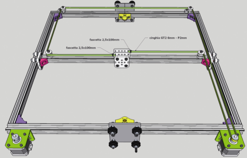
The system we used for moving the extruder is named XY core; you may find more details online, at the following web page. The mechanism at its basis is supplied with two motors that act on the positioning of the print head on the X and Y axes (by means of two different 6 mm pitch 2 mm GT2 belts) at the same time; by using two belts (instead of a very long one) the positioning errors are reduced, since a single long belt is more prone to being deformed, with respect to two different belts (natural deformations will affect both belts in the same way, therefore there won’t be differences between them). The only requirement is that both belts must have the same tensioning.
Thanks to this technology and to the feeding system, in which the motor that pushes the filament is found on the chassis, and the filament reaches the print head by means of a bowden, there are inferior masses moving, which enables the reaching of higher printing speeds, with a high accuracy.
We entrusted the movement on the X and Y axes to the print head, and this enables – with respect to the cartesian Z-head method (the one used by the 3Drag, to be clear) – a more orderly chassis structure, in addition to a quicker printing and to a greater accuracy (thanks to a lower inertia).
Another difference between the 3D4040 and the 3Drag is that the latter has the Y motor mounted on the X carriage, while on the 3D4040 the motors for the X and Y axes do not move, they are both fixed to the frame of the Z-axis carriage. On the other hand, it is the print bed that is moved on the 3Drag: this causes (because of significant masses moving) a great loss of steps and – above all – vibrations when there are very tall items, this has consequences on the finishing of the upper part of the object itself.
As for the 3D4040, the resolution, that is to say the minimal movement that may be obtained on the Z-axis for each micro-step, is equal to 0.000625 mm; such a measure is given by:
Z = screw pitch/3200
in which the screw pitch is the step of the threaded bar that acts as driving force, and that is activated by the stepper motor: in our case that’s 2 mm. We are talking about micro steps, since (and as for the 3Drag), even in this machine it is possible to set the control for fractions of a step, and up to 1/16, therefore, since the stepper motors are the usual ones, the NEMA 17s (having 200 steps/rev); with them the maximum amount of micro-steps is equal to 200×16=3,200.
Extruder
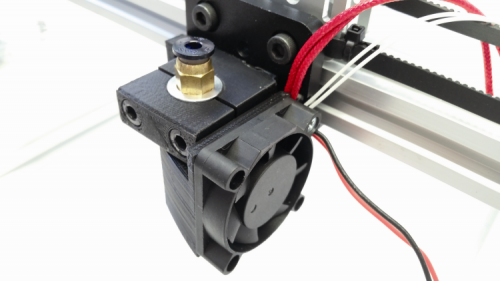
The 3D4040 printer is innovative also because of the extruder; it is based on a very light print head, the E3D V6, used for 1.75 mm filaments; it enables a considerable reduction in the masses moving, and therefore to print faster. Moreover, the printer supports nozzles having various diameters: from 0.3 mm (for those who need very detailed prints) and up to 0.8 mm (for those who want to reduce the printing time).
The lightening of the print head is obtained (as abovesaid) by the fact that while the 3Drag’s extruder included the motor for the dragging of the filament, here the print head is divided from the feeding system, that is opportunely fixed to the machine chassis, as in the 3D Vertex. In the first case, the filament is directly pushed into the print head, that deals with fusing and extruding it on the print bed, while in the second case the filament reaches the print head (that by means of this technique is a very light one) by means of a small teflon pipe (having an internal diameter of 2mm).
The print head used in the 3Dgiga is manufactured by E3D and is ready-to-use; the model we tested is the E3D V6. This print head has a particularly limited size, it requires however a fixing system that is not a very simple one (it requires a support and a collar that grabs the element in its upper part).
This print head has the filament kept at a temperature that is by far inferior to the fusion one, and at a distance of almost 2 mm from the nozzle, which considerably decreases the unavoidable deformations that would cause slowdowns or even obstruct the interior of the passage. The narrowing placed in the lower part (that joins the heating block to the rest of the body) is the winning solution for obtaining the proper thermal cutting, thus preventing that part of the heat generated from the heating cartridge is dissipated from other parts that are not the veritable nozzle, thus allowing a high reactivity and a yield with a minimal waste energy. The cooling of the print head’s aluminum body is guaranteed by the air flux that is generated by a 40×40 mm (12 Vcc) fan, that is directly applied to it, by means of a dedicated clip (that has been designed in 3D and printed in PLA).
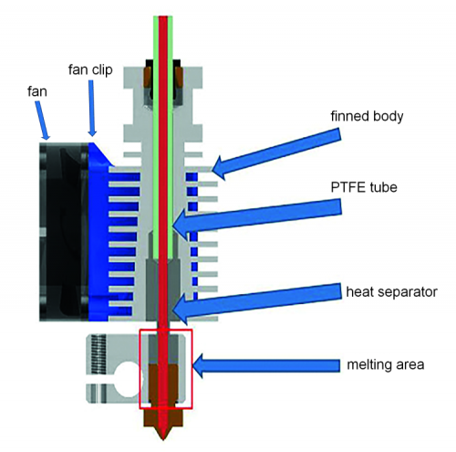
The heating element is a 40 W cylindrical cartridge (Ø 6×21 mm), powered by 12 Vcc, and inserted into a 20x16x11 mm aluminum block. This enables the reaching of temperatures that are suitable for extruding PLA and ABS (250°C). A brass nozzle may be mounted on the print head, by means of a hole that may vary, from 0.3 to 0.8 mm. The control of the temperature is entrusted to an NTC thermistor. As for the settings of the PID, a function found in the Marlin (the version we used is: 1.1.0-RC8) will be used, that enables to carry out the autotuning (as regards PID Autotune, information may be found here and to determine the three values to assign to the Kp, Ki and Kd parameters.
The same procedure is used as for the heated print bed.
As regards the print bed, glass has been chosen because of a reason: given the big size, in order to avoid that it bends during the printing, it must be made out of a material having a high rigidity, and also a low cost. The 6 mm tempered glass proved to be an excellent compromise and it granted satisfying results, even when under heating. If we had used some metal, we would have needed something heavier, at least to obtain the same rigidity.
Circuitry
The controller of the 3D4040 printer is the same of the 3Drag, but it requires that an SSR (a solid-state relay) is used, in order to manage the print bed’s heating element, and so to avoid the overheating of the tracks and of the power connector (that is placed on the board); since the base surface has been multiplied by four, we need a much more powerful heater here, one that absorbs current for a value that taxes the MOSFET (that does not have a dissipator) and the printed circuit (and the connector as well) for the powering of the controller board. The one we tested exceeds 200 watt!
As for the wiring, it is essentially the same of the one of the 3Drag, with the last generation controller, and moreover it has a second Nema 17 stepper motor on the Z-axis, given that the print bed is lifted by two threaded bars, each one of them is activated by its own motor (they are synchronized since they are connected in parallel).
The controller board is based on an ATmega 2560 microcontroller, it shares a good deal of the RAMPS’ (RepRap Arduino Mega Pololu Shield) hardware. The ATmega2560 processor has as much as 256 kB program memory and operates with a 16 MHz clock, it is therefore powerful enough and may host the Marlin firmware we modified in order to tend to the 3D4040 printer.
Our board is directly programmed by the Arduino IDE and has a USB connection for this purpose, so that it may be connected to the computer by means of a common miniUSB cable; the same port enables the control via PC, while printing.
The circuit mounts four driver modules for the stepper motors (3DDRIVER), given that we have a motor for each of the X and Y axes, and two for the Z-axis, in parallel, and a fifth motor that is used to command the mechanism that pushes the plastic filament, by means of the bowden, and into the extruder; moreover, the board has three MOSFETs that enable us to drive two heaters (one for the print bed and the other one that heats the extruder’s nozzle) and a low voltage fan, in addition to a USB/serial converter, so to interface the ATmega with the computer and with a power stage, that completes the set.
The drivers for the stepper motors are the modules manufactured by Open Electronics (cod. 3DDRIVER); each one of them is essentially an Allegro A4988 integrated circuit; that’s a very versatile one, since it may be set both for defining the direction of rotation of the driveshaft and the number of degrees the motor’s rotor must carry out when receiving each command; in other words, it is possible to decide if to rotate the driveshaft by a step at a time or by a fraction of step (1/2, 1/4, 1/8 or 1/16), when we give the command pulse, and depending on the accuracy we wish to obtain. Therefore, it supports the microstep mode.
The motor moves, at every pulse sent by the ATmega to /STEP, and according to the settings of MS1, MS2, MS3; in our case, since we set the maximum dividing factor, for a complete step we need 16 pulses, and therefore (with our NEMA 17s) a complete revolution requires 3,200 pulses of the microcontroller.
Please notice that – for each controller – the /STEP line has been connected to an NPN transistor, that is needed as a current amplifier in order to drive a LED, that will pulse in a way that is analogous to the one of the corresponding microcontroller’s command line, so that we may supervise what occurs. Therefore, in the case – during the tests or the usage – the motor does not rotate, despite the fact the corresponding LED is still pulsating, it means that the problem is internal to the driver or due to the motor, that is to say, it’s in the wirings.
It is understood that, since the LED pulsates at the same frequency of the command pulses, it is possible to see it flash only when the corresponding motor rotates at a very low speed, given that the human eye sees an always lighted diode at 25 Hz already.
Let’s move on now to the MOSFET drivers, that are used in order to power the heaters and the fan: they all are BUK6215-75Cs, and are capable of supplying a drain current reaching 57 A, and of supporting a Vds in interdiction state, and equal to 75 V; their very low Rdson (a 15 milliohm max with an Id of 15 A) enables us to minimize the dissipated power and therefore to directly solder them to a track of the printed circuit board (that thus acts as a dissipator).
When on the board, the MOSFETs do not have a dissipator, since very low currents are used (that’s in the order of 2÷2.5 A as for the extruder’s heater, that has to be connected to the HEATER1 output). Since the board was born for the purpose of being used with the 3Drag, the MOSFET commanding the heated print bed is also lacking a dissipator, and therefore it may not commute the direct current that is directed to the heater of the glass print bed of the new printer; therefore, we will have to connect the HEATER2 connector to a solid-state relay (SSR) that, in turn, will power the print bed, as per the wiring diagram shown in these pages.
The microcontroller reads the temperature probes that return the feedback on the heaters’ activity; these probes are NTC thermistors, to be connected to the THERM1 and THERM2 contacts. More exactly, the sensor that is internal to the extruder must be connected to THERM1, while the NTC that detects the temperature reached by the possible heated print bed must be connected to THERM2.
The probes enable the stabilization of the temperature for the extruder and for the heated print bed; without this retroaction – and even supposing to work with a constant current, and that it corresponds to a certain temperature – the environmental and operational variations could alter the temperature at which the plastic material to be extruded is brought, with obvious resulting problems as for the deposition and the composition of the item being printed. By detecting the extruder’s temperature (by means of the voltage found at the THERM1 ends), the microcontroller verifies the figure by means of the set one: if the temperature exceeds the set value, it decreases the current in the heating filament, while it is increased in the opposite case. Similar considerations may be applied to the heater of the heating print bed, that is anyway an accessory and its absence does not compromise the machine operation; in fact, the base firmware deactivated the control of the print bed and of the temperature reached, that is useful (coupled to the printing client) in order to start the printing itself, but only once the print bed has reached the temperature in full capacity. Please notice that the NTC thermistors that have been used for detecting the temperature of the extruder and of the heated print bed are both 100 kohm ones at 25 °C.
The transistors are all driven by means of a PWM signal, so to modify the power given to the users, and so to check the heat generated by the heater’s resistors and the speed of the fan for the item’s cooler, but that occurs with very low losses, since the MOSFETs operate in an on-off mode. Even the output commanding the solid-state relay (SSR), to which we entrusted the task of commuting the power for the print bed’s heater, generates a very low-frequency PWM command signal.
Each one of the outputs that have been destined to the heaters have been supplied with a LED that pulsates along with the corresponding PWM signal (at about 4 Hz), thus enabling a visual verification of the operating state; on the other hand, the PWM for the cooling fan is at a higher frequency and the corresponding LED will appear as always lighted.
The controller board reads the state of the limit switches on the three-movement axes; all the corresponding lines of the microcontroller are provided with an internal pull-up, that is activated by the firmware. The limit-switches are switches or commuters that – when conveniently placed – are activated by the print bed or by the support of the print head arriving at the end of the track; in our case, they are placed on the chassis. When a limit switch is activated, the microcontroller receives information (in the form of a logical state) and deals with stopping the corresponding movement, and recalling the carriage, or with the raising of the print head.
Our board is provided with three inputs for the limit switches: XSTOP that corresponds to YSTOP that coincides with ZSTOP.
For each limit switch, three contacts have been provided: +, S and -. This solution has been chosen, so to be able to connect both limit switches of the electromechanical kind (microswitches and such) and optical detectors, composed of a photodiode and of an infrared LED that are one before the other in a cavity: when the carriage comes, the small flap that is fixed to it will pass through the cavity and stop the light that should reach the photodiode, thus activating the limit switch.
In our case, since we use some limit switches, we connect each one of them between S and – (ground). Thus the condition connected to the arrival at the end of the track coincides to the high level on the corresponding input.
As regards the communication with the computer, the controller board uses an FT232RL USB/serial converter by FTDI, that contains the logic needed in order to transform the data from the TTL serial format to the USB one, and for the sorting of the data coming from TXD and RXD on the DP and DM pins.
Practical implementation
Let’s move on now to the creation of the printer, that consists in a mechanical part and in an electronic one; as for the first one we have to mount the mechanism, that is composed of a chassis and of moving parts: therefore a bearing structure, carriages for the movement on the Z, X and Y axes, print bed, print head group, the moving components.
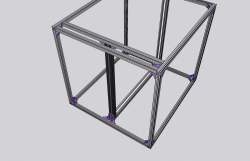
As a first thing, you will have to assemble the chassis frame, by joining two 690 mm 20×20 aluminium bars and two 588 mm ones; the assembly of these bars (and of all the other ones that are used in the printer) will be carried out by means of die cast aluminium angle brackets, of M5x10 TCEI screws, and of TM5 nuts. Such a solution grants rigidity and stability to the machine chassis.
In the middle you will place another 690 mm bar, thus obtaining a situation such as the one in the figure.

At the corners of the chassis base, four 570 mm 20×20 bars will have to be mounted vertically; they will be the uprights of the chassis. Another 570 mm 20×40 bar will have to be fixed vertically, and then two 690 mm 20×20 aluminum bars and two 588 mm ones (the same ones you used for the base) will have to be fixed to the chassis’ upper part, by means of three angle brackets for each corner.
Please take the last 570 mm 20×40 bar and fix it to the center of the 588 mm 20×20 bar; at this stage, please place the “T” (the one you just obtained) on the chassis, thus obtaining what is shown in the figure.
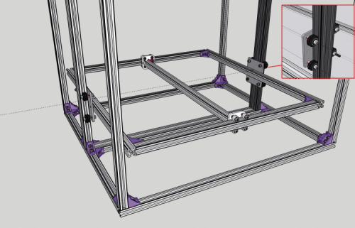
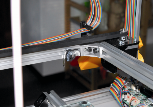
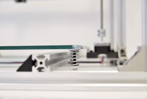
It is now the moment to create the system composed of the Z-axis chassis and the corresponding side carriages, that are needed in order to enable its movement; each one of them has an aluminium plate as a base, and will be applied to the dedicated upright, it will be fastened by means of some V-pulleys, blocked by M5x30 screws and nuts.
Now, please prepare the mechanism that enables the horizontal sliding of the print head, that is to say the X-Y mechanism: it is based on a 564 mm 20×20 aluminum bar, at its ends, the carriages shown in detail in the figure are applied. Such a system enables the movement on the X axis and the Z-axis chassis is shown, complete and mounted.

All that is left is to mount the X-Y chassis (that is to say, the one sliding on the Z axis) on the Z carriages we previously applied to the side uprights that act as a guide; we will obtain a situation as shown in figure, in the picture’s detail you will see a Z-carriage from the external side.
It is now the moment to create the axes movement: as a first thing, please place two motor clamps on the base’s right side and place a 1.5 A NEMA17 motor (short body) between them. Please do the same on the left side.

Please fasten (from top to bottom) a 500 mm Ø 8 mm pitch 2 mm trapezoidal screw, so that it may come out from its corresponding worm gear (the yellow one in figure), for about 4-5 cm; please apply an aluminium joint to the lower end of the threaded bar and secure it, and then please fasten the bars until the driveshaft for each motor is completely inserted into the corresponding joint. Please take the two supports for the Z bearing and insert a bearing in the dedicated place, and secure them to the chassis, at the same level of the upper angle bracket.
Now, please prepare the printhead carriage (it will enable the movement on the Y axis): take the specific black anodized aluminium square plate and place it on the guide of the X carriage with the corresponding pulleys, and then fasten an aluminium plate to it, one that has been specifically shaped for fixing the belts. Please complete the Y carriage by mounting the second plate for the belt fixing.
Please place the two NEMA17 motors (the ones for the command of the transportation on the X and Y axes) on the X-Y chassis, and then supply them with toothed pulleys. Please take the toothed belt and divide it into two parts having the same length (about 2.5 m each); then apply it – in this order – to the right motor’s pulley, to the central pulley, and at a later time fix it to the front plate of the Y carriage (by means of a strip). Please stretch out the rest of the belt on the other pulleys, until the other plate is reached: there, it will be fixed, still by means of a strip. Please carry out the same operation with the other belt. The transportation group will appear as in the figure.
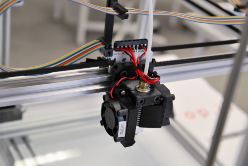
Let’s move on now to the print head, that will be applied to the printhead carriage, by applying the fan’s clip on the winged body of the print head; the wires will have to go as in and will have to be secured by means of a strip.

Once this has been done, you will have to mount a 40x40x10 mm fan (the fan will have to be oriented so that the air flow goes to the print head) on the same clip. Please apply the plastic conveyor to the lower end of the air duct (and directions below), by means of self-threading screws. After that, please fix a second 40×40 fan to the conveyor (it must blow towards it).

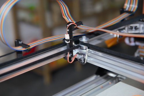
At this stage you will have to mount the microswitch limit switches, the first two will have to be worked, so that the small flap is reduced to less than 33 mm, and then bend the end slightly towards the body. You will have to enlarge the mounting holes, by means of a 3 mm drill, so that they may be mounted via 3MA screws.
After that, please fix the Y-axis microswitch to the bar, by means of a M3 screw, so that it clicks when the Y carriage is at a distance of about 42 mm from the carriage plate placed on the left end. Please fix the X microswitch to the bar, so that it clicks when the X carriage is at a distance of about 85 mm from the internal edge of the bar on which the motors are mounted. Please take the Z-axis microswitch and shorten the small flap at 23 mm. Please fix it to the bar, so that the corresponding contacts are at a distance of about 2 mm from the angle bracket placed below.
The placement of the limit switches is shown in the figure.

Let’s move on now to the print bed: please place it (take care when handling it!) with the holes’ countersink directed downwards and insert a screw (from bottom to top) in each one of them. At a later time you will have to place a 5×20 plain washer and a 2x15x26 spring on each one of them. Please take four small aluminum triangles with a square angle and apply them to the two 627 mm aluminum bars, so that a side of the print bed is at a distance of 88 mm from one of the ends of the bars themselves.
The block that is composed of the print bed mounted on the two aluminum bars should now be applied to the printer’s chassis base, by means of specific screws.
Once the group has been mounted, you will have to act on the four adjustment screws of the glass print bed, so to have it approximately at the same level, and fasten them as much as needed for the springs to be slightly tightened and to avoid excessive swingings (the definitive, fine tuning will be carried out during the machine testing, according to how the printing is carried out).
Once this has been done as well, it is possible to prepare the spool holder: please insert the support arm in the dedicated slot of the corresponding clamp, and then slide the latter towards the bottom, until it abuts; you will then fix the spool holder to the chassis, at about 150 mm in height from the base.
Let’s move on now to assembling the feeding mechanism (also called Feeder): please fix the bowden holder to the 2.5 A NEMA17 (long type) motor and insert the dragger on the driveshaft, while taking care to align the latter’s grub screw to the flat part of the pivot itself. Please fix the dragger to the driveshaft, after having aligned its toothed pulley with the guide holes of the filament, found on the bowden holder. Please apply the bearing to the dedicated half shell and mount the corresponding half shell, then please fasten the stepper motor to the screw coming out from the support bearing.
Please place now the filament guide, that will bring the filament from the motor to the print head; such a guide is the bowden, that has to be fixed to the chassis, and bent, with the help of a compression spring. After that, please make the small PTFE pipe (the one coming out from the head) go into the upper spring hook and then fix the latter to the chassis’ upper bar, by aligning it to the left cavity of the upright.
Please fix the bowden to the Z carriage’s guide (in the left cavity) by means of the screws and finally insert the small PTFE pipe in the joint (please push it to the bottom so to lock it in place). The power supply unit will have to be as shown in the figure.

At this stage, the mechanism has been completed and we may move to the circuitry, that consists in a controller board and in the PCB for the wirings of the print head, since as for this printer we considered (in order to make the wiring a more orderly one) to connect the head and the fans’ wires to a breadboard, on which there are some terminal boxes for the purpose, and on the short side of the latter, where there is a flat connector. The breadboard (as shown by the track in the dedicated box and in the attached table, up in this page) creates the connection between the connector and the terminal boxes.
You will then have to fix the said breadboard (by means of the dedicated holder) to the central bar of the printhead chassis, that shows the wiring as regards the print head.
The controller board is supplied as an assembled, ready-to-use one, and with the bootloader and the firmware loaded. Please notice that the base firmware has been written for the operations without a heater for the Z print bed that is always active, thanks to the #define DISABLE_Z instruction, that has been set to “false”, in order to block the two motors during the operation, so that they do not move; this is needed in order to avoid unwanted rotations, due to the vibrations.
As regards the wiring, and after having blocked it on the machine chassis, by means of spacers, please remember to connect the wires of the stepper motors to the corresponding connectors, via some flat cables that you will have readied. The correspondence between motors and connectors is as follows: the X-axis motor goes to X-MOTOR, the one for the Y-axis must be connected to Y-MOTOR, the one raising and lowering the print head goes to Z-MOTOR, while the one that makes the extruder’s filament advance goes to E-MOTOR. As regards the limit-switches, they respectively go to XSTOP and YSTOP, while the one for the print head must be connected to ZSTOP.
The extruder’s heater must be connected (you don’t need to worry about the polarities) to the HEATER1 contacts, while the corresponding NTC goes to THERM1.
Please fix the network power supply to the left side of the chassis and connect the network cable to the terminal box in this way:
YELLOW/GREEN cable – ground terminal;- BLU cable – N terminal;
BROWN cable – L terminal;
After that, please connect the power supply’s output to a red/black cable having a plug at the end: it is to be inserted in the controller board; the red wire goes to the +V terminal and the black one goes to the -V terminal.
It is convenient to fix the network cable to the lower part of the power module, by means of a 2.5×200 cable tie, that will be needed so to protect it from accidental rips; it is useful to protect the terminal under the network voltage, by means of a plastic lid (the one that is specific for that kind of power supply) that prevents the accidental contact.
Once this has been carried out, the printer is ready; after the controller board has been connected to the computer by means of a USB A/mini USB cable, you will be able to start the machine with a test print. Before doing that, however, please have the print bed perfectly at the same level, with respect to the nozzle, by acting on the adjustment screws of the springs, so to verify if the motors are moving correctly and in the right direction, and if they are synchronized among them; if the head does not move it is because a micro switch (either the X or the Y one, or both) has not been connected, and therefore the board sees it at the end of the track.
Settings
In order to obtain an optimal operation, we need to calibrate the board’s driver; the procedure is as follows: with the printer being powered, take a multimeter set to 2 Vcc, end of scale, and a small flat head ceramic screwdriver (it is possible to use a metal screwdriver but you will have to be careful to touch the trimmer only, in order to avoid short circuits).
Please keep the black tip of the tester on the board’s ground and the red tip on the pad placed on the first driver’s chip, and then adjust the trimmer until you read 0.41V on the multimeter. Please do the same with the other drivers, and remember that the one on the Z-axis has to be calibrated to 0.65V, since it has to power two motors in parallel.
Conclusions
Well, we have ended, at least for now. In the second and last installment we will propose some add-ons, among which the installation (and customization of the activity) of the heater for the print bed and a control panel display for the machine used in the autonomous mode. We will also see how it is possible to adjust the default micro-step mode, and to operate on the controller board’s firmware.
From opestore
3D4040 – The big 3D printer – 40x40x40 cm

Related Posts


One Comment
Leave a Reply
-
 Arduino ISP (In System Programming) and stand-alone circuits
We use an Arduino to program other ATmega without...
- Posted 12 years ago
-

-

-
 GSM GPS shield for Arduino
Shield for Arduino designed and based on the module...
- Posted 12 years ago
-
 Small Breakout for SIM900 GSM Module
Some post ago we presented a PCB to mount...
- Posted 13 years ago
-
 Join Maker Faire Rome 2024: Innovation Unleashed at Gazometro Ostiense | Calls Now Open!
All Calls Now Open for Maker Faire Rome 2024...
- Posted 2 weeks ago
-
 Building a 3D Digital Clock with Arduino
Project to create a digital clock consisting...
- Posted 4 months ago
-
 Acoustic amplifier – in DIY Kit
This kit creates a microphone amplifier with an output...
- Posted 5 months ago
-
 Creating a controller for Minecraft with realistic body movements using Arduino
Project of a controller that maps body movements...
- Posted 5 months ago
-

Pingback: 3D4040: printing big! | Open Electronics