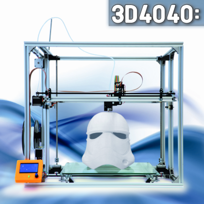
It is no longer a problem, nor it is expensive, to print big size items and terrain models: we showed you that by means of our new creation, the FDM 3D printer that our well-equipped readers will be able to create, thanks to the assembly kit. The machine is capable of manufacturing solid prints having a maximum size of 400x400x400 mm, and made of different kinds of plastic materials (PLA, ABS and so on), that’s an example of how to create a high-performance product that has a certain limited cost: we feel sure it won’t disappoint you.
[bctt tweet=”New FDM (Fused deposition modeling) 3D printer capable to produce 40x40x40 cm (64,000 cm3) objects.” username=”OpenElectronics”]
In this article we would like to widen the perspective and explain how to implement some add-ons that will optimise or customise its operation; in particular, we will explain how to install the heater for the print bed, that is very useful for printings that turn out to be particularly long ones, and with materials such as the ABS (that tends to “shrink”); we will also explain how to adjust the Marlin firmware, so that you will be able to manage it under all its aspects, such as for example the possibility to start the printing only when a certain temperature has been reached.
Moreover, we will take advantage of this to give some useful suggestions to those who want to customise some operation aspects, such as for example the micro-step mode and the firmware settings, and also to describe the application (for both hardware and software) of the command panel for the stand-alone usage of the 3D4040 printer.
The heated print bed
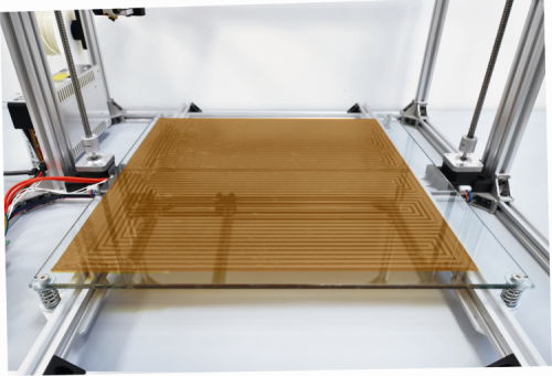
Here we will not explain (since we did it already quite a few times in the past) what is the purpose of the heater; we will limit ourselves to repeat that by keeping the heated print bed hot we manage to make the solidification of the deposed filament a more progressive one, and to oppose the warping of the first layers of the item being printed. The heater of the 3D4040 printer has been upgraded to match the increased size of the printing bed and has, therefore, a 40×40 cm size, so to supply heat in a uniform manner; the need to heat a greater area than the one in the 3Drag (that’s four times greater, actually…) implies that the power must be consequently adjusted, that is to say, it must be increased fourfold.
In our case, we are dealing with a heater having a copper coil that has been isolated on both sides by a Kapton sheet; when powered at 12 V it enables the development of as much as 240 watt, that corresponds to a nominal absorption at exactly 20 A (in fact 240W/12V is indeed 20A).
The tests we carried out with the 3D4040 prototypes, equipped with a heater, registered 21.2 A with a cold start, and 20.4 A when at full operation; it is clear that with a cold start the current is a greater one, since the electric resistance of each conductor (and therefore, also the one of the heater’s coil, made of a copper alloy) grows when the temperature grows. It is important to know the current used at a cold start, in order to assess the expected absorption for the 3D4040’s power supply (that’s a 29 A one) and to evaluate how this may influence the operation for the rest of the machine. It is also important to know the current used in full operation since it is the one that is absorbed when the stepper motors and the extruder’s heater are working. The tests we carried out and the measures have shown that the power supply is an adequate one, at least at least when controlling the heater in PWM. However, the current of the heated print bed – as hinted in the previous installment – must be switched by a solid state relay and the corresponding output of the controller board (HEATER 2) will be used only to supply the command voltage; the SSR will then commute the heater’s power circuit.
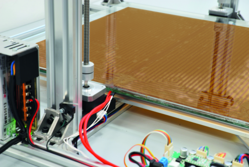
In order to heat the print bed, we need to apply the heater, that is an adhesive product by 3M, on the opposite side of the one where the item to be printed is deposed, that is to say on the inferior side. On the same side, you will fix an NTC thermistor that will detect the temperature of the heated print bed, and you will do it by means of the Kapton sheet, near the edge of the heater itself, and then connect it by means of two wires to the controller board’s THERM2 input. When applying the adhesive heater, please make sure that you cleaned the surface of the inferior side of the print bed well, by means of some isopropyl alcohol, so to avoid dirtying it (also, do not touch it with fingers, otherwise you will leave grease from your hands, thus dirtying it).
Please make the heater adhere well, by progressively stretching it out (starting from a side), and please prevent the creation of bubbles, that would not allow a uniform heat transfer to the glass print bed, because there would be high thermal resistance zones arising.

The two heater’s cables and the ones of the NTC must laterally exit from the left upright and have to be extended towards the solid state relay. In order to limit the losses (they cannot be avoided, given the current at play here…) we recommend that you keep the solid state relay close to the power supply, so to limit the length of the connecting cables. We would like to remind that the relay dissipates a certain amount of heat, and it is, therefore, appropriate to apply it to an aluminium foil or to another heat dissipator (it is enough if it grants a thermal resistance of 13÷15 °C/W), to be well fixed to the machine chassis, by means of screws and metal triangles. It is convenient that the fixing is carried out to one of the base bars; please avoid the upright, given that it would be deformed by the heat and such a deformation – even though a minimal one – could alter the accuracy of the movements in the raising system for the print head (Z-axis and therefore the X-Y chassis).

The power connections and the ones towards the print bed’s heater require a sheathed unipolar cable (a power cord…) having a 1.5 mmq section; anyway please consider that the heater is already supplied with adequate cables (with a 40 cm length), in order to simplify the wiring: in fact it will be enough (because of the limited distance between the parts involved) to connect a heater’s cable to the positive clamp of the switching power supply and the other one to the + clamp of the solid state relay. You will have to bring the – pole of the latter to the negative one of the power supply itself, by means of a part of the sheathed cable having a 1.5 mmq section.
As for the SSR command, on the other hand, it is not required to use a particular cable: any cable will do, even a flat one, from 0.25 mmq upwards. Please respect the polarities, that is to say HEATER 2’s + goes to the input’s + and the – goes to the -.
Commanding via MOSFET
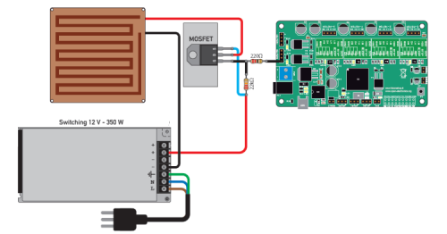
Instead of resorting to a solid state relay, it is possible to command the heated print bed in an easier and cheaper way, by means of a power MOSFET; for convenience’s sake we will choose a P channel one, so that it will be possible to drive it directly by means of the HEATER 2 output (instead of the solid state relay). The corresponding wiring diagram is shown in the figure.
The power component we used is an IXTH90P10P by Ixis (or you may use a similar one) that has been encased into a TO-247 case (having 3 terminals at 5.08 mm pitch); it must be connected to the gate at the negative pole of the HEATER 2 connector while the source goes to the positive pole of the power supply by means of a wire having an adequate section (still 1.5 mmq for the powering and wires coming from the MOSFET’s drain and source), while the drain must be connected to the positive pole of the heater, whose negative pole will go to the power supply’s ground.
All the recommendations we gave just a while ago (when we explained the wirings and the placing of the solid state relay) are still valid. Also, the MOSFET must be fixed to an aluminium triangle (or to another heat dissipator) having a thermal resistance that here must not be above 10÷12°C/W; the dissipator is needed since – from the tests we carried out – we noticed a 0.3 V voltage fall at 20 A between drain and source (the MOSFET’s insertion resistance is about 15 milliohm) and this causes a 6 watt power dissipation.
The heat radiator must be isolated via a grey Teflon sheet or via a mica foil, spread on both faces by means of some white silicon paste, since the metal part of the component is in electric contact with the drain terminal, that is potentially positive when the MOSFET is turned on, while the printer’s structure is connected to ground. The dissipator must, therefore, be anchored to one of the base bars, by means of screws and metal triangles. The connections to the MOSFET’s terminals must be isolated by means of a heat-shrink tube, so to avoid short circuits, should it lean on the metal of the dissipator itself.
Until now we dealt with the hardware for the heated print bed, however, to supply the printer with such an accessory implies that some modifications must be made to the firmware; we will start by saying that the printer’s firmware has been written for the operation with the print bed’s heater, if it has not been mounted, we may disable it from the printing client.
The 3D4040 firmware is the Marlin 1.1.5 and in this version the possibility to activate the heater (therefore, by managing the temperature on the THERM 2 input and the heater via the HEATER 2 output) is provided, and also the one to prevent that the extruder starts before the heated print bed reaches a certain temperature, that is to say the temperature value that has been specified on the printing client.
The minimum extruding temperature has been set to 170°C; this means that until the said temperature has been reached, the machine will not start extruding.
The instruction enabling such an operation mode is:
#define EXTRUDE_MINTEMP 170
In order to control the print bed via PWM we need to delete the comment from the following line:
#define PIDTEMPBED
and to comment as follows:
//#define BED_LIMIT_SWITCHING
We would like to remind you that commenting means to have the command preceded by // so that it is not executed since the compiler sees it as a comment.
For the purpose of controlling the heated print bed, it must be noticed that there is an option, that is to say, to control the heating of the print bed via a traditional relay or via SSR or MOSFET, although in ON/OFF mode.
It is possible to do that by commenting the following line:
#define PIDTEMPBED
and by deleting the comment from:
#define BED_LIMIT_SWITCHING
However, the tests we carried out made us understand that this is not an optimal solution, since that it implies a 0.3 mm warping of the print bed (due to hysteresis), given a print bed having a 45 cm side.
For such a reason the PWM mode is to be preferred, since it limits the stress caused by the continuous and cyclic expansion (when heating) and contraction (when cooling), that is caused by the heater’s operation being an intermittent one, and one that moreover mechanically stresses the base of the item, given that the print head – as explained above – gets warped.
Please notice that before using the printer it is needed to carry out the heated print bed’s auto-tune, in order to adjust the PID; but before you do that, please verify that this is set in the firmware:
#define TEMP_SENSOR_BED5
otherwise, you will have to set the instruction like this. Once this has been done, from the printing client, please write in the G-Code commands section:
M303 E-1 S60 C8
and then press ENTER: the software will carry out a test, in order to identify the most suitable PID values. In the end, that calculated values for kp, ki and kd will be shown; please write them down in the related firmware section, so to have them be the effective ones; they have to be in the place of the default ones, that are as follows:
#define DEFAULT_bedKp 334.42
#define DEFAULT_bedKi 25.39
#define DEFAULT_bedKd 1101.30
modifying the micro-step
Let’s move on and take a look at the microstep mode, that as for the printer – or better said, for its controller – has been set to 1:16 by the manufacturer.
The drivers for the stepper motors have this mode set as the default one by the manufacturer, however, if you want to modify it you will have to refer to Table 1, that shows the driver settings by means of the control pins.
table1
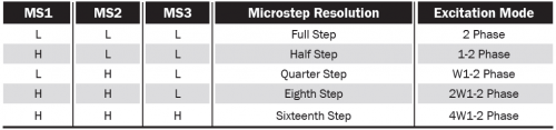
In order to change the default settings of the drivers you will have to cut – on the lower side – the three thin tracks that connect the jumper pads, two by two, and then to solder some standard pin-strips to them, in order to enable the manual step selection by means of some 2.54 mm pitch jumpers; it is not needed to carry out this operation on all of them, it will be enough to do it as for those you’re interested in.
It is understood that if you modify the microstep setting, it becomes necessary to update the firmware (so that it generates the pulses at the required frequency, and not at the standard one, used for the division by 16), you will have to act on the corresponding instruction, that defines the pulses that the microcontroller must supply in order to obtain a certain movement on the corresponding axis, also considering the pitch of the trapezoidal screw as regards the Z axis, and the pulley’s teeth as for the X and Y axes.
The corresponding section in the Marlin firmware is:
HARDWARE
#define DEFAULT_AXIS_STEPS_PER_UNIT {80,80,1600,150} // default steps per unit for 3D4040
#define DEFAULT_MAX_FEEDRATE {500, 500, 5, 50} // (mm/sec)
In the instruction, the commas separate the settings regarding the different motors (X, Y, and Z axes and the extruder’s motor).
It must be noticed that the firmware considers that the motors on the Z axis are kept blocked (they are brought in position but are not to be released) during the printing, in order to avoid unwanted movements in the printhead chassis.
If you want to keep Z active, please look for the “#define DISABLE_Z” instruction and change the parameter, from true to false.
In the Marlin firmware, the Z axis is always active, because of the instruction set to “false”.
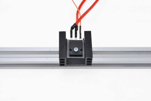
command panel
The 3D4040 may be customized, by mounting a command panel supplied with a graphical display that enables the management of the printing, directly from the controller, and without the need to connect a computer.

This panel is the same one we showed you in time for the “mother” printer, the 3Drag; it also supports an SD-Card in which all the files to be printed must be written, and from which the microcontroller of the printer’s controller board acquires them for the printing, so to operate autonomously, without the need to have a computer that is turned on and connected until the end of the printing; this means considerable savings in electricity, if we consider that particularly complex item requires 3 days or more!
The command panel may be interfaced by means of a specific connector to the controller, and it is provided with a rotary encoder with the clicking function, used for selecting the menu entry that has been highlighted and located via the rotation.
The firmware has been set for managing the panel, but it operates even if you do not connect it; please consider that if you connect the PC, it will prevail on the panel, even if the display continues to operate and to show the activity.
On the panel there is a hardware reset button, to be used only in the case in which the printer is freeze.

A plastic case has been provided for the command panel, it is to be printed by means of the 3D4040 (or any other 3D printer) once it has been completed; you may use the filament of the color you prefer.
As for the reset button, we still advise to keep it short, so to prevent that it is accidentally pressed, during the operation; don’t forget that with a machine such as the 3D4040, because of the great size of the items to be printed, it even takes days in order to complete the work, and an accidental reset may have you to throw them away; and also we shouldn’t forget about the money that would be wasted in electricity and in the plastic filament that would be wasted, unless you have a machine capable of recycling it.
Conclusions
Here, we end describing our printer: we showed you its strengths and features, and guided you through its assembling, and proposed you some useful add-ons, so that you may use it in a better way. For the moment, we stop here, but we are set to keep you updated in case of further customizations and upgrades of this project.
From openstore
3D4040 – The big 3D printer – 40x40x40 cm
3D Printer Full Graphic Smart Controller with 3Drag adapter
3D Printer Heated Bed Power Module
