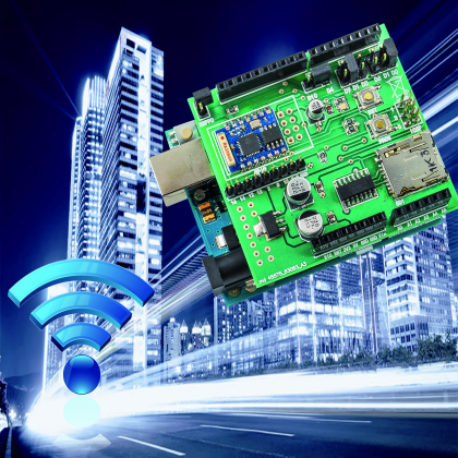
It supplies Arduino with the WiFi connectivity and the external memory support on a SD-Card; it is based on a new module that is completely programmable, and offers the best value for money, with a very limited energy consumption that make it ideal for battery applications.
It is not the first time that we propose a shield that is dedicated to the network wireless connection, and there are two reasons for that: on a side, Arduino’s world is interested in applications that connect to smartphones and tablets or that may access Internet via WiFi, and on the other side there is the passionate activity of the manufacturers that are always launching new products that are more updated and competitive, with a good frequency.
The shield proposed in these pages is based on a new module that – in comparison to those used in the past (e.g.: those manufactured by Microchip) – has a very limited price, even if it keeps having remarkable features. The module is named ESP03 and is based on the ESP8266 integrated circuit, so to operate in an autonomous way inside a WiFi network; for the purpose the integrated microcontroller possesses an EPROM Flash memory, on which to run a dedicated program. The possibility to run an internal program enables the management of some pins (GPIO), in order to create a system that may interface external peripherals: all of this, without need for much external hardware. In the ESP03 module, in addition to the ESP8266, there are: an integrated antenna, a 4 kB non volatile memory and a power supply manager, besides some passive components. It must be noted that there are various WiFi modules based on the ESP8266, that distinguish themselves because of the form-factor: in our shield we considered the ESP03 – the one we are going to deal with – but it is also possible to mount the ESP01.
Therefore the module – with a very small encumbrance – enables to create a complete stand-alone system for the WiFi. The module is also fitted so that it may interface an external logic, on which to run even some more complex software, as we will see in this article.
The component is destined to the following applications: Home Automation, mesh network, industrial wireless control, Baby Monitor, Network Camera, sensor networks, wearable electronics, wireless location-aware devices, Security ID tag and wireless positioning system signals.
The features and the implemented functions are:
- it is compatible with 802.11 b/g/n;
- Wi-Fi Direct (P2P), soft-AP;
- TCP/IP stack support;
- TR switch, balun, LNA, RF amplifier and network coupling are integrated;
- PLL and power supply manager are integrated;
- transmission power in 802.11b: +19,5 dBm;
- integrated thermal sensor;
- support for the diversity antenna;
- a 32-bit CPU;
- SDIO 2.0, SPI, UART;
- STBC, 1×1 MIMO, 2×1 MIMO;
- A-MPDU, A-MSDU;
- only 2ms needed for the connection and for the data packet transfer;
- current drawn when in off state is under 10 µA;
- power consumption when in standby mode under 1 mW (DTIM3).

The family of ESP modules.
Such a chip is born in order to supply the WiFi connectivity to mobile or wearable devices that are battery powered, and thus implements low energy consumption modes; in fact the module may be operating in different modes: active mode, sleep mode and deep sleep mode, accordingly to the active peripherals.
In the sleep mode, the radio module is turned off while the real-time clock and the watchdog remain active, the absorption is only 12 µA; in this mode it is possible to program the internal timer so that it may activate the radio module at regular intervals in order to send or receive data. Even the external signals may activate the radio module and enable the transmissions. By means of the internal software it is also possible to reduce the emission power and to reduce the energy consumption in applications for which short range communications are required (such as wearable devices). The CHIP_PD line, that is available on the external connector, allows to bring the module to the low power state, with a power absorption close to zero.
The power absorption during the active mode reaches a maximum of 215 mA at the maximum transmission power, with a 802.11b protocol at 11 Mbps, dropping to 145 mA with a 802.11g protocol at 54 Mbps, and also only 60 mA for sending a 1.024 byte packet with an antenna power of -65dBm.
Inside the ESP8266 chip we find a 32 bit microcontroller, completed of ROM, RAM and SRAM for the program and data; the chip has several digital I/O lines and analog inputs, in addition to different communication ports such as I²C, SPI and UART. The communication ports may act as slave, so to interface memories that are external to the module, and to expand their functioning. The available digital lines are sixteen, and configurable as inputs or outputs, all have a pull-up resistor and are configurable in order to generate an interrupt; some lines may be configured so to remotely activate different energy saving modes. Some analog input and output lines – based on a PWM sigma-delta converter – are available as well.
The chip has been designed in order to operate at a 3.3V voltage, with a tolerable maximum of 3.6V, the digital inputs have a dedicated circuit (overvoltage protection) so to protect the integrated circuit from input voltages above 6V.
Lastly, we mention the support for all the most modern encryption protocols:WEP (RC4), CCMP (CBC-MAC, counting mode), TKIP (MIC, RC4) o WAPI (SMS4), WEP (RC4), CRC, WPA, WPA2 and WPS.

An integrated circuit, many WiFi modules
On the market there are various versions of the WiFi module that are based on the ESP8266 chip, and that are differentiated as for size and pins made available on the communication connector, besides the different versions of the internal firmware.
ESP-01: the most common module, with an antenna that is integrated in the PCB
– 2×4 contacts pinout, 2,54 step;
– antenna on PCB;
– 2 GPIOs;
– UART URXD/UTXD;
– reset and CH_PD (Power Down) function;
– size: 14,2 x 14,2 mm.
ESP-02: module with a connector for an external antenna, that is compatible with a breadboard
– 2×4 contacts pinout, 2,54 DIP step;
– 2 GPIOs;
– UART URXD/UTXD;
– reset and CH_PD (Power Down) function;
– size: 14,7 mm x 14,2 mm.
ESP-03: SMT (Sufrace Mount Technology) version, with all the pins made available and a ceramic integrated antenna
– 2 rows of 7 contacts, 2,54 mm step;
– ceramic integrated antenna;
– 7 GPIOs;
– UART URXD/UTXD;
– reset and CH_PD (Power Down) function;
– size 12,2 mm x 17,4 mm.
ESP-04: SMT (Sufrace Mount Technology) version with all the pins made available but without antenna
– 2 rows of 7 contacts, 2,54 mm step;
– external antenna;
– 7 GPIOs;
– UART URXD/UTXD;
– reset and CH_PD (Power Down) function;
– size: 12 mm x 15 mm.
ESP-05: Version with UART communication only and antenna connector
– 2×4 contacts pinout, 2,54 mm step;
– U-FL connector for an external antenna;
– no GPIO;
– UART URXD/UTXD;
– reset and CH_PD (Power Down) function;
– size 14,2 x 14,2 mm.
In order to complete the ESP8266 chip’s description, we will refer the functioning of the single pins in Table.

Function of the pins in the ESP8266 chip.
In some modules, some LEDs are found: the red LED indicates that there is power voltage (POWER STATUS) while the blue LED flashes when the module starts the boot (MODULE STATUS) or communication operations.

ESP03 module’s pinout.
Circuit diagram
In the following parts of this article we will deal with the usage of an ESP8266 chip along with an Arduino board, in particular we will describe the shield that has been especially designed for this module. In addition to the ESP03 (signed U3 in the circuit), some jumpers for the settings are found in the shield, along with a multifunctional SD-Card reader (SD1), that is interfaced by means of a 74HC4050 (U1) level shifter to Arduino; the adapter is needed in order to transform the TTL signals of Arduino’s lines (that are used for the SD management at 0/3.3V, as required by the memory cards). The SD slot enables the memorization of various data types: for example, a webpage, or the recordings of a data-logger on the web, and much more. But anyway it is not needed for the functioning of the WiFi shield and therefore it is an accessory for future developments.
The whole logic is powered with the 3.3V drawn from the LDO U1 regulator: the latter draws the said voltage – opportunely filtered by the C2, C4, C5, C6 capacitors – from the 5V supplied by Arduino’s line of the same name; the LD1 LED, having the R2 resistor in series.

Given that the shield is centered on the ESP03, it is the case to devote a few paragraphs to the purpose of deepening our knowledge on the subject of the functions of the ESP8266 integrated circuit, that is at its base.
When designing the shield’s printed circuit we considered the possibility to use both the module in the 01 version and in the 03 version, moreover with some jumpers it is possible to select different operating modes. The SDCS jumper (SD chip select) allows to select the pin to be used for the SD Card management, by default Arduino’s library uses pin 4. The ESPPD jumper (ESP Power Down) – if shortcircuited – enables the selection of the D7 pin, for the purpose of the control of the module’s functioning mode. In this mode, by means of Arduino’s D7 line it is possible to turn on and off the module, depending on the needs and with considerable energy savings: otherwise the module would remain always active. In the shield, all the ESP8266-03 module’s pins are also available, in a strip connector: this is useful for those who want to deepen their knowledge on the subject of the chip’s stand-alone usage. Both the modules that we considered have a standard serial communication interface that is compatible with Arduino; it consists of two data lines (TX and RX) that may be directed towards the hardware serial, or on the D8 and D9 pins, that are manageable by means of a software serial. The ESP8266 chip’s communication selection occurs by means of the jumpers, accordingly to what in table 2, and occurs anyway, considering Arduino’s intrinsic limitations: by using Arduino’s software serial in order to communicate with the ESP8266 module, the hardware serial remains available for the programming and the debug communication; by using Arduino’s hardware serial (UART module), the communication with the PC will create conflicts and therefore it will not be possible to program Arduino, nor to send debug messages to the Serial Monitor. The last option considers the possibility to connect the ESP8266 chip with the PC, by means of the USB/serial converter on board of Arduino, the Atmel328 microcontroller is not interested by the communication and the UART module must be disabled by loading a sketch that does not use the hardware serial (the UART module is disabled by default).

Communication jumpers’ layout.

Shield’s hardware connection.
Let’s see now the practical usage of this shield, by starting from some simple applications that will allow us to become familiar with the implemented functions. The ESP8266 chip’s management is carried out by means of some simple AT commands, to be sent serially, and even the data sending and receiving is carried out serially. It is however needed to pay attention to the version of the module you possess, since the first ones to be sold with a version 080 firmware were communicating at a 115 kbps speed, while the more recent ones (having a version 09xx firmware) operate at 9,600 bps. The possibility to communicate at a speed of 9,600 bps allows to manage the the module via the software serial communication, that can be easily implemented by means of the specific library that is available in Arduino’s IDE, thus leaving the hardware serial port free to communicate with the PC, and allowing for an easy debug functioning.
AT commands available for the ESP-8266 module
General functions
AT – Test AT start up Test
AT+RST – Restart module
AT+GMR T+GMR – View version info
AT+GSLP Enter deep-sleep mode
ATE – AT commands echo
WiFi functions
AT+CWMODE – WIFI mode
AT+CWJAP – Connect to AP
AT+CWLAP – List available APs
AT+CWQAP – Disconnect from AP
AT+CWSAP – Configuration of softAP mode
AT+CWLIF – IP of stations
AT+CWDHCP – Enable/Disable DHCP
AT+CIPSTAMAC – Set mac address of station
AT+CIPAPMAC – Set mac address of softAP
AT+ CIPSTA – Set ip address of station
AT+ CIPAP – Set ip address of softAP
TCP/IP functions
AT+ CIPSTATUS – Information about connection
AT+CIPSTART – Start connection
AT+CIPSEND – Send data
AT+CIPCLOSE – Close TCP or UDP connection
AT+CIFSR – Get local IP address
AT+ CIPMUX – Enable multiple connections
AT+ CIPSERVER – Configure as TCP server
AT+ CIPMODE – Set transfer mode
AT+ CIPSTO – Set server timeout
AT+ CIUPDATE – Update through network
+IPD – Receive network data
As for these first examples, in which we want to become more familiar with the chip, we will see to communicate with the ESP chip directly from Arduino Serial Monitor, thus leaving the board’s ATMEL328 microcontroller unused. Please load a sketch that does not use the serial port (Blink.ino will be fine) on Arduino, and set the jumpers so that the module may communicate with the PC.
Please open Arduino Serial Monitor and set the communication to 9,600 bps, and activate both the end of the line and the return (both NL and CR), therefore please send the AT string and wait for an answer, if everything is fine the module will reply with “OK”. This first transmission does absolutely nothing, but allows to understand if the module is active and operating; at the start the module sends the “ready…” string anyway. The sending of the AT+RST string enables the execution of a device software reset, it will answer with the “OK” string, followed by the manufacturer’s name and by some pieces of the chip’s internal data. The AT+GMR string allows to know the firmware’s version installed. With this configuration the ESP8266 module will be able to communicate with whatever PC application such as Processing, or with any serial monitor.

We may become even more familiar with the module, by trying to connect to the home WiFi; the AT+CWMODE=1 command allows to set the access to a router while the AT+CWJAP=”nomerete”,”password” allows to access it. In order to know if the connection came to a successful ending, it is possible to ask the module about the connection’s status, by means of the AT+CWJAP? command, while in order to know the IP address assigned by the router, the command is the following one: AT+CIFSR.
As soon as we are connected to the network, we may test some of the module’s functions; as an example, by making it operate as a server towards the PC; in order to do so it is needed to start a very simple client on the PC, for example by using a portable software named SocketTest, a sort of serial monitor for Ethernet networks. We will send the following commands, in sequence:
AT+CWJAP=”nomerete”,”password”
AT+CIPSTART=”TCP”,”192.168.1.128″,9999
AT+CIPSEND=4
please send a 4 characters string – for example, “ciao” – and disable the sending of the end of the line and the end of the line and the return.
The reception of a string from the server will be signalled by the “+IPD” string, followed by the number of characters received and then by the text received.
We tried different configurations, by using the module both as a client and as a server and also with a UDP communication started, in any case it has always been simple and quick to set the module with a few AT commands.
In the various available listings, you will always find a first part that is related to the communication mode with the ESP module and to the debug mode, in fact in these first examples it is always very handy to consider a mode for the purpose of viewing the data transiting from the module. By connecting the ESPTX jumper to the D8 line and the ESPRX jumper to the D9 line, it will be possible to manage the module by using a software serial, and by leaving ATME328’s UART module free to communicate with the PC via the debug and programming functions. This mode works only with the ESP modules communicating at 9,600 bps, a mode that anyway shows its limits in the case of management of important data flows, containing more than a hundred characters: that is the case – for example – of the webpages’ management.
We will remember that all the examples we proposed must be customized, by typing the name of your WiFi network and the password, respectively in the SSID and PASS fields.
In addition to the classic application as a webserver, we have designed an application like a web client, so to show the ease with which it is possible to request information from Internet websites. The only data to be supplied regards the server’s address and the name of the page to be accessed; in the listing you will find (as comments) different examples of settings we personally verified, among which there is the interrogation to Google’s server or the reading of meteo data from the openweathermap’s server. This last example is particularly interesting for the possibility to know the weather conditions by querying the closest weather station, without the need to use any sensor; there is also the possibility to request the weather forecast for the next days; the only data to be inserted is the code for the city you are requesting the data, and it may be acquired at this address: http://openweathermap.org/help/city_list.txt. Similarly it is possible to query Yahoo’s server in order to know the date and the current time.
In these last examples we have used the classic html syntax that is composed of three sections: request (request row), body (message body) and header (additional information). The request section, in turn, is composed of three fields. The first field is the access method and it may be of the GET (information recovery), POST (information sending), HEADER (like GET, but it only receives the page’s header) type. After the method, the URI (Uniform Resource Identifier) must be specified, that is to say the address of the page we want to access, and lastly, we need to specify the protocol’s version, in our case,.mpi : a method, an URI (the address of the page we are requesting) and the “HTTP/1.1” protocol version.

The body section simply contains the veritable request, while the header section contains the “HOST:” header, in our case. As an example, here is a request for weather conditions, that is carried out by sending the following: “GET /data/2.5/weather?id=3164699 HTTP/1.1 HOST: api.openweathermap.org”
The request must be sent after that, obviously, we connected to the server by means of the instruction: “AT+CIPSTART=\”TCP\”,\””DEST_HOST”\”,”DEST_PORT”\r\n”
All of the examples have been tested with modules having a 09.02 firmware version, that turns out to be the most stable one, and the one that is free from bugs; at the moment there isn’t yet a final firmware version, and on the Internet it is possible to find even more recent versions, but that are yet to be tested. It is however possible to install a different firmware version, by means of a simple procedure that we will now describe. Among the files in this installment you will find a folder named firmware, that contains an executable file named ESP8266_flasher.exe, which is used in order to load a new firmware on the module; we already made a firmware version 09.02 available, that you will normally find installed in the ESP8266-01 modules.
Once the software has been started (it does not require installation), it is enough to specify a COM port to be used for the communication with the module and to open the .bin file; in order to know which serial to use, you may use the information provided by Arduino’s IDE when the Arduino board is connected. Please set the module in the communication mode with the PC and enable the module’s boot mode, by placing the GPIO0 line to ground by means of a jumper cable, afterwards please reboot the module by placing the CHPD line at a low level for a moment, even here a small jumper cable will be enough. After the reboot, the module will be set in boot mode, ready to receive the new firmware. Please click on the Download button, then, in order to activate the loading and wait for the operation to be concluded. Please use the AT+GMR command in order to verify if the module is operating correctly and which firmware version has been installed.
SD-Card Classification
There are different SD-Cards available for sale, and they may be distinguished because of the technology used, that evolved in the years, starting from the basic SD Card. Not all of them are compatible with the other ones, even though the manufacturer tend to generally keep the backward compatibility. The various types are described as follows, one by one.
SD
SD capability, going from 128 MB to 2 GB.
Default Format: FAT16.
The SD cards operate in all the host devices supporting SD, SDHC or SDXC.
SDHC
SDHClogoSD High Capacity (SDHC ™) is a SD ™ card, based on the SDA 2.0 specifics.
Capability going from 4GB to 32GB.
Default Format: FAT32.
Since SDHC operates in a different way from standard SD Cards, this new format is not compatible with the host devices supporting only the SD ones (128MB – 2GB). The greatest part of the readers and host devices that have been built after 2008 should be compatible with SDHC.
In order to guarantee the compatibility, please look for the SHDC logo on both the boards and the host devices (cameras, etc.).
SDXC
SDXClogoCapacità SD Extended (SDXC ™) is a SD ™ card, based on the SDA 3.0 specifics.
The SDXC capabilities may vary from 64 GB to 2 TB.
Default Format: exFAT.
Since the SDXC uses a different file system – named exFAT – and since its functioning is different from the SD standard cards, this new format is not compatible with the host devices that only support the SD ones (128MB to 2GB). The greatest part of the host devices that have been built after 2010 should be compatible with the SDXC. In order to be sure of the compatibility, please look for the SDXC logo, both on the boards and on the host devices (cameras, etc.).
NOTE: card readers that are found inside laptops, starting from 2008 (and before) may NOT support the SDXC cards. The SDXC cards operate only in readers that are compatible with SDHC (not the SD readers) and if the computer’s operating system supports exFAT.
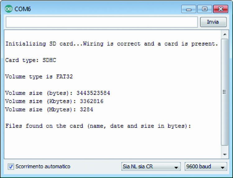
Having a SD available for the purpose of saving data enables us to create an interesting data logger that has the function of accessing the Internet network, in order to find useful information. In the case of a data logger, a surely important data is given by the date and time in which the data is saved; a function usually carried out by a RTC (Real Time Clock) that is interfaced with Arduino. Having the possibility to access Internet, it is easy to query a NTP server, in order to know the accurate date and time, without the need to execute any initial setting. A first simple test – in order to verify if anything works correctly – consists in inserting a SD card in the slot (a micro SD, to be accurate) and to execute the cardInfo.ino sketch, that is available among the system samples; please make sure that the SDCS jumper is in the D4 position. You may see from the images the answer displayed on the Serial Monitor, concerning a SD HC cat4 having 8GB and FAT32 formatted, that we used for our tests. With the ReadWrite.ino sample you may verify if the reading and writing function are working properly.

New firmware installation.

Serial Monitor for the communications with ESP.
At this stage we are ready to implement our data logger, as a simple example we are going to save the environmental temperature’s value, as measured by a simple integrated circuit such as the LM35.
The sketch for the data logger function is named ESP8266_DataLogNTP.ino, and it may be downloaded, along with the other files enclosed to this magazine’s number. In order to test this program, as a first thing you will have to type name and password of your WiFi network in the SSID and PASS fields. The temperature sensor will have to be powered by Arduino, by the GND and +5V pins, while its output will have to be connected to the analog input, AN0. This sensor supplies a voltage of 10mV for each detected Celsius degree; therefore, in order to better the resolution, it is needed to set the full scale for the A/D converter at 1.1 volts, by means of the analogReference(INTERNAL) instruction. The temperature will be acquired by converting the value read by the A/D converter by means of the following equation: TEMP = analogRead(A0)/9.31. For this sketch we considered the usage of the ESPPD (ESP8266 Power Down) line, that allows to turn off the module when it is unused, thus drastically reducing the energy consumption.
In the sketch’s opening part it is possible to define the communication mode between the ESP8266 module and Arduino. The default mode that we considered consists in making the ATmel328 microcontroller communicate with the WiFi module by means of a software serial and to let the hardware serial free for the debug function. The DEBUG variable may be set on true or false, depending on the fact you want a report that is more or less complete as regards the communications with the WiFi module.
In the case you wanted to manage the WiFi module via the hardware serial, it is enough to set the jumpers so that the ESPTX and ESPRX signals may be respectively connected to D0 and D1, but please remember that each time that you want to program Arduino, you will have to disconnect the module – by removing the jumpers – otherwise the two communications will be in conflict.
SD Test.
In the case two hardware serials are available, as in the Arduino Leonardo board, the main serial will be used for the debug while the secondary serial (Serial1) will be used for the communication with the module.
In the section related to the setup, the module and the SD are initialized, also verifying they are operational.
In the loop section the code related to the data log function is contained, the first part deals with recalling the function for the access to the WiFi network; five tries at most are allowed. The request for the date and time follows, by recalling the requestTime() function, that deals with querying the NTP server; the strings related to the date and time are available by means of the getDateString() and getTimeString() functions. These functions allow to format the data and they may be modifications, depending on which format we want to use; this is important in the case of a following processing, by means of a spreadsheet concerning the acquired data.
In order to extract the date and the time from the return string, we will use the time library, that has been specifically studied for this function; as usual it is possible to copy the whole folder (named time) inside Arduino’s library folder and then to reboot the IDE.
We need to remember that the time obtained from the NTP server is referred to the Greenwich meridian (now GMT Greenwich Mean Time); thus we will have to take the Italian time zone (+1) and possibly the daylight savings time (+1 in the summertime) into account; for such a reason we considered the UTCcorrection correction variable, that is set to 7,200, so to consider the 3,600 seconds related to the time zone and the 3,600 seconds related to the daylight savings time.
Then the module disconnects from the WiFi network and is turned off, so to save energy.
The following code lines are used in the sketch, so to build the string that will be built in the SD Card:
String dataString = getDateString();
dataString += ” “;
dataString += getTimeString();
dataString += ” AN0=”;
dataString += String(analogRead(A0));

SD Card reading and writing test.
This string may be modified as needed, by adding (or not) other values or separators. The writing on the SD Card follows as well as the idle cycle, waiting for a new acquisition. The time interval between the acquisitions may be set by means of the timeToLog variable, that is set to 60,000 ms (1 minute) by default. We considered that the module remains turned on only for the short time needed in order to connect to the network and to receive the data from the NTP server; for the rest of the time between a log and the following one, the module is brought to a power-down status, thanks to the D7 pin’s signal that commands the EPS8266 integrated circuit’s CH_PD pin.
This allows for considerable energy savings, even though continuous connections to the WiFi network are needed.
In the SD Card you will find a file named DATALOG.TXT and containing all the acquired values, as shown in figure. This sketch is compatible with modules in which the 9.02 and 9.03 firmware versions (such as the one installed on our shield) have been installed.

Report concerning the sketch.

Content of the sketch’s log file.
Conclusions
We may define the ESP as a small but great module, give the versatility and the particularly reduced package, whose strong point is surely the price, ranging at a few dollars. Even when purchased in a form that is already installed in a handy shield, the final price is certainly more limited than the ones of the classic shields we were used to; the disadvantage is the one to have a firmware that is still immature and not yet optimized, in a way that would have allowed to take full advantage of the chip’s hardware capabilities. Thanks to the SDK being released by the manufacturing firm, the community was mobilised in order to find new and advanced ways to use this module, and above all the possibility to use it in a stand-alone mode, without the need to have it interfaced to an external programmable logic. But we will deal with this in a following article.

From openstore
ESP03 module Wi-Fi transceiver – GPIO
WiFi Shield ESP8266 for Arduino
