Makes Raspberry Pi suitable to be used in “professional” environments, sports a power source, an UPS, a RTC clock, a watchdog function, RS232 and RS485 converter and a buzzer. All in one.
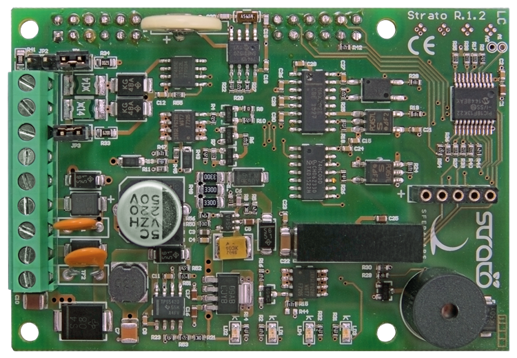
In the previous posts in which we presented different solutions – and above all in the professional daily work – we always recommended, in the case of the usage of Raspberry Pi that is not purely that of an amateur, to supply it with a protection and safety system, capable of avoiding the problems due to malfunctions and accidents, be it internal ones or produced by external causes. The Strato Pi board was born in order to prevent this problem, and has been designed so to be placed above Raspberry Pi, enabling the installation by means of different kind of connectors. The board’s compactness has been determined by the usage of a 4-layer printed circuit board. The board’s circuitry frees different GPIO pins, that may be used for other applications. In this case a double connector must be provided for.

Main Power Source
The line for the main power source is composed of different stages: a first stage so to protect from overvoltages and polarity inversion, in particular TF2 is a resettable fuse, and destined to protect from the voltage fluctuations, up to ±500V/2ohms 1.2/50µs. The D7 diode is designated with the protection from the overvoltages, while the D8 diode protects from polarity inversions. The network of capacitors in parallel (C9, C10 and C11) forms the filtering stage, followed by a step-down DC/DC converter that is based on the U6 integrated circuit, that generates the 5V voltage to power Raspberry Pi and the other utilities of the UPS board, that require a 5V power source. The U6 integrated circuit is a TPS5420D by Texas Instruments, a PWM DC/DC converter that internally integrates a N-channel MOSFET in the high-side configuration. This configuration allows an efficiency of 95% and allows to supply a 2A output current. Moreover, the TPS5420D integrates the functions concerning the current supply only after having reached 5.5V, the limitation of the overvoltages and the thermal protection with automatic shutdown. The power chain is completed by the stage that is centered on the U4 MOSFET. The U4 MOSFET, when conducting, supplies power to the Raspberry Pi, while when it is in interdicted it disconnects the power from Raspberry Pi. The U4 MOSFET’s gate is driven by the Q4 transistor, that in turn is driven by the RC4 output of the U1 microcontroller, a PIC18F13K22 PIC that hosts the greatest part of the software functions of the Strato Pi board. The “service” stage, formed by the U8 integrated circuit, is a linear regulator that draws the 5V voltage from the DC DC converter (U6) and supplies the 3.3V voltage right to the U1 microcontroller, that also manages – in addition to powering Raspberry Pi – the “watchdog” function, that we will describe later.

UPS
The Strato Pi board’s versions that have UPS also provide the possibility to use and manage the system power from a 12V sealed lead acid battery, used as a buffer, so to take care of a possible lack of voltage from the line of the main power source. The battery’s management circuit allows the power from the battery to act immediately, in the case of lack of voltage from the main line: this function is essential in order to avoid that Raspberry Pi’s operating system disconnects and, obviously, it must be able to recharge the battery when the main power is found. The battery’s power circuit is composed of a protection stage, of a “switch/deviator” stage that enables the power from the battery (on the basis of the power from the main line being found or not), and of a stage for the regulation of the output voltage. The TF1 thermal fuse and the D3 diode protect the input from overvoltages, polarity inversions and overloads. Under “normal” operating conditions, that is to say when voltage is found on the main power line, the circuit formed by the D5 diode and by the Q2 and Q3 transistors, powered by the voltage coming from the main power line, keeps the gate of the IRF2731PBF (U2) P-channel MOSFET transistor at a high level. With this configuration, the P-channel MOSFET does not conduct and consequently the “battery” remains “disconnected” from the DC/DC (U6) conversion stage. At the same time, the SHDN “signal” is at a high level and enables the U3 IRF2731PBF (U2) integrated circuit, a step up DC/DC converter that raises the power voltage from 5V to 15V, so to recharge the buffer battery. The charging current is limited to 30mA by the network of the resistors, R1, R48 and R49. When the power is missing from the main line, the circuit composed of the D5 diode and of the Q2 and Q3 transistor is no longer powered by the voltage coming from the main power line and, consequently, it brings the gate of the U2 MOSFET to low level, the latter starts to conduct and allows the U6 DC/DC converter to be powered, by drawing voltage from the buffer battery. The SHDN “signal” goes to a low level and interdicts the functioning of the U3 DC/DC converter that stops the battery charging. Under this configuration, the DC/DC conversion circuit that refers to U6 is powered by the battery, and Raspberry Pi is powered via U4, even in this case. The LD1 LED is lighted in order to warn about the intervention of the buffer battery and the VON “signal” goes to a high level, communicating the intervention of the buffer battery to the U1 microcontroller. In turn, U1 communicates to Raspberry Pi that the power from the battery is active, bringing Raspberry Pi’s GIO26 pin to the ON state. In this way, it allows Raspberry Pi to manage the state in which the voltage is lacking and, if needed, to program a controlled shutdown. Later on we will describe the software functions that are available on Raspberry Pi, so to manage the conditions signalled by the Strato Pi board, and in particular the mechanism that allows to switch off Raspberry Pi in a controlled and safe way, in the case in which the main power has been missing for too much time and the battery is no longer capable of ensuring a stable power source.
RTC (Real Time Clock)
The heart of the RTC circuit is the U10, the MCP79410 integrated circuit by Microchip, a RTCC chip being widely used that, in addition to the clock and calendar functions, makes a 64 byte SRAM memory available to the user: it is powered by the BT1 battery as a buffer, and has 1K of EEPROM memory and a 64 bit EEPROM memory that is protected from writing. The integrated circuit’s clock is regulated by the Y1, a 32.768 kHz crystal. The 3.3V power source is drawn at the U8 DC/DC converter’s output. The communication with the management software on Raspberry Pi is carried out by using the I2C bus, in which Raspberry Pi acts as master unit and the RTC chip as slave. A BT1 lithium battery (a CR1220 model), is used in order to power the RTC circuit when the voltage is missing and during the storing periods; during operating conditions in which the board is permanently powered, the lithium battery’s duration may reach 10 years. In any case, it is possible to substitute it by unsoldering the two terminals from the printed circuit board.
Serial Port
In order to strengthen the “industrial” calling of the Strato Pi, a two-phase protocol conversion for the serial communication has been added. A conversion stage of Raspberry Pi’s TTL serial protocol to the RS232 standard that is driven by the U5 integrated circuit, MAX202ECSE, and a conversion one, still from Raspberry Pi’s serial port to the RS485 standard. Obviously, from the applications it is possible to use only a mode at the time, either the RS232 or the RS485. In order to avoid possible problems as interferences and ground loops, the protocol conversion circuits are isolated as regards the power source and the signal lines. The power source uncoupling is obtained by using a high efficiency DC/DC converter, created by means of the Mornsun B0505LS integrated circuit. The U5 integrated circuit’s inputs/outputs are uncoupled with respect to Raspberry Pi’s serial line by two high-speed opto-isolators, respectively U13 and U14. The LD3 and LD4 LEDs warn, by flashing, of traffic being found on the serial line. The conversion from the TTL serial protocol to RS485 requires an additional stage, created around the U7 integrated circuit; that’s a half-duplex low-energy transceiver for RS485; the data “direction”, keeping in mind the communication speed (baud rate) and the number of bits to transmit/receive, does not need for particular configurations as regards Raspberry Pi, and is completely managed by the U1 microcontroller (PIC18F13K22). All of this is needed in order to allow the applications being executed on Raspberry Pi to communicate through the serial port towards RS232 or RS485 devices, without the need for modifications imposed by the conversion process. The RS485 line uses 620 Ohm pull-up and pull-down resistors, R33 and R34, that may be disabled by removing the JP3 and JP1 jumpers. The R41 100 Ohm terminator, between the lines A and B, may be enabled by shortcircuiting the JP2 jumper. Ultimately, the communication with RS232 and RS485 devices is a completely transparent one, from the point of view of the applications that are hosted on Raspberry Pi.

Hardware Watchdog
The boards of the Strato Pi family implement a device that creates a watchdog, namely a “hardware” one so to distinguish it from the software watchdog that is implemented in the GNU/Linux kernels, but that is actually managed by an opportunely programmed U1 microcontroller, PIC18F13K22. Here, the circuit consists – almost exclusively – in the PIC microcontroller. The only “attachments” are the R17, R35, R37, R38, and R39 pull-down resistors, respectively found on Raspberry Pi’s I/O pins, GPIO5, GPIO6, GPIO13, GPIO19 and GPIO16, that are shared with Raspberry Pi, the two voltage dividers are composed of the R40, R42, R36 and R54 resistors, so to adjust the levels towards Raspberry Pi’s GPIO 12 and GPIO26 input pins, to be used respectively in order to warn about the watchdog’s timeout state and about the intervention of the buffer battery. When using the watchdog functions it is possible to implement a complete system for the management of the voltage drops, and to guarantee the safety and the integrity of the applications being executed on Raspberry Pi. The watchdog that is implemented on the boards of the Strato Pi family is completely independent from the internal watchdog of Raspberry Pi’s operating system, and therefore it may be used for the control of the applications being executed, but it is not capable of managing an external device such as the Strato Pi boards. The “information” exchange between Strato Pi’s watchdog and the applications being executed on Raspberry Pi is carried out by means of some Raspberry Pi’s GPIO pins and of a “code” that is based on the recognition – by both devices – of some combinations of “levels”. From Raspberry Pi’s side, the “levels” of the control pins may be managed by means of simple scripts to be downloaded from the Strato Pi boards’ support website; we will describe them later. The control software for the watchdog being executed on the PIC18F13K22 microcontroller solves the problem of Raspberry Pi’s shutdown, in the case in which the lack of voltage from the main line continues for an excessive period of time, and of the following restart, since the watchdog controller – in the case Raspberry Pi communicates the start of a controlled shutdown – completely disconnects the power from Raspberry Pi after a minute, in order to give it later, only when the power on the main line has returned.

BOARD INSTALLATION
The Strato Pi boards are supplied with all the connectors that are pre-installed, and therefore they don’t require solderings. In order to install the board on Raspberry Pi, it is sufficient to correctly place the connector or, better, to place the two connector’s sections on the Strato Pi board, in correspondence of Raspberry Pi’s GPIO connector, and to connect them together after having carefully verified the alignment of the pins. It is absolutely compulsory that this operation is executed without any power source being connected to the board or to Raspberry Pi. After the installation of the Strato Pi board on Raspberry Pi, it is absolutely FORBIDDEN to power Raspberry Pi via its micro USB socket or via the USB ports. The power source has to come uniquely from the Strato Pi board. Another warning is the one to pay attention that the tracks of the Strato Pi board do not touch Raspberry Pi’s areas connected to ground, such as the USB and Ethernet connectors. For the purpose, we suggest to use some spacers having an appropriate length, to be placed on the mounting holes that have been provided for both the printed circuit boards. In the case you had chosen the Strato Pi Server configuration, this has already been assembled in its container, that is suitable to be installed on a standard DIN rail. Even the Raspberry Pi microcomputer is already included in the container and therefore there is not even need to open the container itself if not, possibly, in order to modify the settings of the jumpers that configure the terminating resistors of the RS485 lines, that will be described later. Still in the case of the Server configuration, the micro SD Card with the operating system may be inserted by means of the specific slot – that has been obtained on a side of the container – by using a clip or a ball pen, so to insert it completely in its housing, without having to open the container, even in this case.
The connections that refer to the C-clamps that are found in the Strato Pi board are indicated in the figure The clamps at the ends of which we have to connect the cables coming from the power source connected to the main power line are indicated with VCC. Power sources that are capable of supplying output voltages between 9V and 28V, and with a current of at least 2.5A, are permitted. Please pay attention to the cables’ polarity. The buffer battery is to be connected to the “Batt” clamps, a 12V gel cell model with an advised capacity of 1.2A, even in this case please pay attention to the polarity. The maximum cross-sectional area for the cables to be used is 1.5mm2.
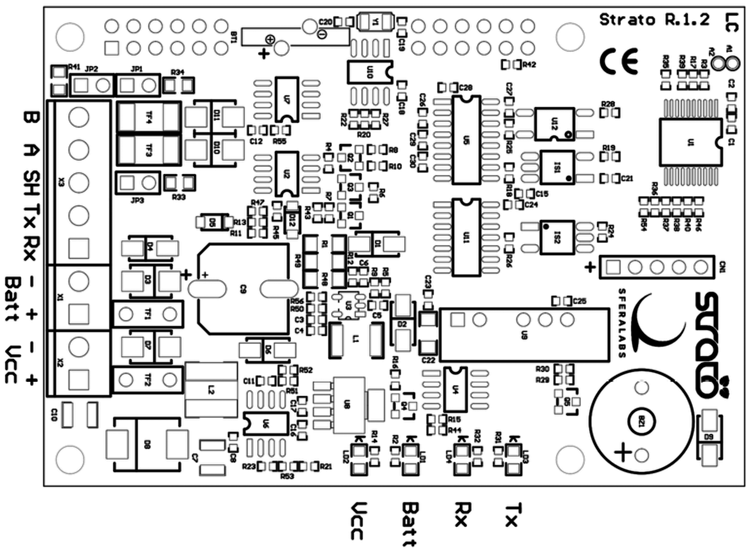
The connections of the RS232 serial port (Tx and Rx) and of the RS485 bus (B, A and SH) depend on the other clamps. After having installed the Strato Pi board on Raspberry Pi, we will connect Raspberry Pi to our home network by means of an Ethernet cable. If we have the buffer battery available, we may connect it to the clamps that have been provided for. You will see that by giving voltage uniquely from the battery, Raspberry Pi won’t start. On the other hand, we will see that the yellow LED is lighted, highlighting the power that comes from the battery. In order to start Raspberry Pi, it is needed to power it from the main power line. We would like to point out that we have to use a power source of at least 2.5A with an output voltage between 9V and 28V. As you connect the external power source, you will see that Raspberry Pi starts and the blue LED lights up, so to indicate that the main power source was found. Please connect to Raspberry Pi by means of the SSH server, as we said many times in the articles that were dedicated to Raspberry Pi on our magazine. The default username and password for Raspberry Pi are respectively “pi” and “raspberry”.
Usage of the GPIO pins
The Strato Pi board uses the pins of Raspberry Pi’s GPIO, that are listed in table 1. If you use the Strato Pi board it is needed to avoid using these pins for purposes that are different from the ones that have been provided.
Table1

Software Installation
On the website of the Strato Pi board’s manufacturer, a series of utilities are available, under the form of shell commands, that allow to control the different functions that we described. As a first operation, please execute an update of Raspberry Pi’s operating system, by typing the following commands:
apt-get update
apt-get upgrade
apt-get dist-upgrade
After that, please download and install the management utilities of the Strato Pi board, by means of the following commands:
cd /usr/local/bin
sudo wget http://sferalabs.cc/files/strato/strato
sudo chmod 755 strato

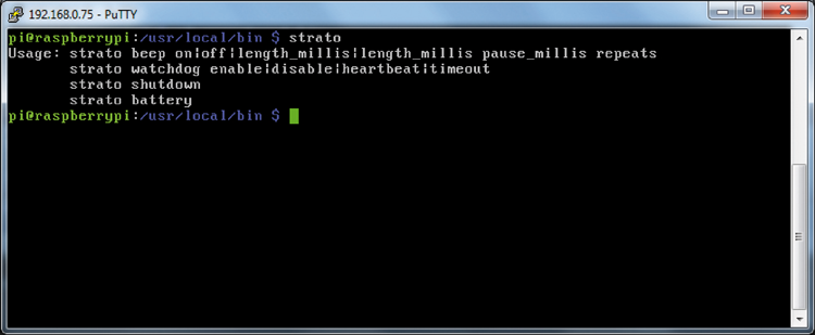
At this stage, if you execute the utility without parameters, you will obtain a synthetic “help” of the utility itself.
strato
Usage: strato beep on|off|length_millis|length_millis pause_millis repeats
strato watchdog enable|disable|heartbeat|timeout
strato shutdown
strato battery
We would like to point out that all the commands have to be executed as a “root” user, or by the general “pi” user, by using the “sudo” (superuser do) command that transfers some of the privileges of the “root” user to the authorized users. If you want to use the RTC functions, it is needed to install the related software and to enable the I2C bus on Raspberry Pi, since – as we already said – the MCP79410 integrated circuit by Microchip uses the I2C bus in order to communicate with Raspberry Pi. As a first operation you will have to enable the driver for the usage of the I2C bus. Please launch the configuration application raspi-config by means of the following command:
sudo raspi-config
Please select the “Advanced Options” entry from the menu, and then the “I2C” entry and select “yes” so to enable the I2C interface, then exit by means of “Exit” and “Finish” and then restart Raspberry Pi:
sudo reboot

Once it has rebooted, please install the “i2c-tools” utility package, that is a useful one for the test of the I2C bus:
apt-get update
sudo apt-get install i2c-tools
Finally, please install the management utility of the RTC function, as shown in figure:
cd
wget http://sferalabs.cc/files/strato/rtc-install
chmod 755 rtc-install
sudo ./rtc-install

If there are no errors highlighted, please delete the installation script and execute a new reboot:
rm rtc-install
sudo reboot
In order to verify the proper functioning of the RTC function, please execute the process that is described as follows, after having verified that Raspberry Pi is connected to the Internet (which should be true if you managed to carry out the previous steps). First of all, please check the date and the time set by the system, by means of the following command:
date
The “date” command returns the system date and the time that “should” have been automatically updated when the operating system was started, by means of the access to one of the Internet servers that supply the “ntp” (network time protocol) service. It is possible to see a possible result in figure.

Now, please verify that the date and time have been memorized by Strato Pi’s RTC clock, by means of the following command:
sudo hwclock –r
In fgure a possible result is still shown. If the returned time and date are not the correct ones, or if an error message has been returend, please update the RTC clock with the system time, by typing the following command:
sudo hwclock -w
The “-w” parameter commands the writing operation as for date and time in the RTC clock. Please execute the previous test again, now, and verify that the two clocks are synchronized. If it weren’t like this, it is needed to verify that Raspberry Pi correctly “sees” the RTC clock on the I2C bus. Please try to type the following two commands:
sudo modprobe -r rtc_ds1307
sudo i2cdetect 1
Please answer “Y” when the “Continue” request appears, as shown in figure:

At the 6f address, you should be able to see the “6f” characters that correspond to the I2C address of the RTC clock. If the clock is not detected the problem could an unsuccessful software installation.
Please verify it via the following command:
lsmod
(list modules) if the “i2c_dev” and “i2c_bcm2708” are found. Once that the RTC clock has been correctly installed and that it is working, date and time will be automatically updated and you will be able to verify it by means of the standard commands for the management of date and time in the GNU/Linux environment.
UPS Management
Let’s get to the main function of the Strato Pi board, that is to say to ensure continuity in powering Raspberry Pi, by means of the buffer battery, when the main power source is lacking. The system behaviour considers that when the main power is missing, Raspberry Pi will continue to be powered by the buffer battery, until the latter has enough charge. When the main power source is available, the battery is slowly recharged by means of a 30mA current. The state of the yellow and blue LEDs indicate the source with which Raspberry Pi is powered. Moreover, the power source may be identified by analyzing the state of the GPIO26 pin of Raspberry Pi’s GPIO.

In order to verify it, please type the following command:
sudo strato battery; echo $?

If the reply is “1”, the power comes from the buffer battery; conversely, if the reply is “0”, the power comes from the main line. During the powering from the buffer battery, it is possible to program a shutdown with a following total disconnection of the power. When the application on Raspberry Pi – the main power source being missing – decides to stop the functioning, it must bring the GPIO16 pin of Raspberry Pi’s GPIO to a high level, so to later request the board’s shutdown. If the main power source is not restored within a minute, the Strato Pi board disconnects the voltage from Raspberry Pi. The one minute delay allows Raspberry Pi to complete the shutdown process. After having disconnected the power from Raspberry Pi, the voltage is given again uniquely when the main power source has been restored. The command in order to start a delayed shutdown process is the following one:
sudo strato shutdown

Watchdog hardware
The watchdog function allows to execute a forced switching off – with a following new switching on – of Raspberry Pi, so to solve – even if in a way that is a bit “rough” – possible crashes of Raspberry Pi’s operating system. The watchdog is usually disabled. In order to enable it, you will have to set the GPIO6 pin to level “1”, from Raspberry Pi. At this stage, as long as the GPIO6 pin remains at a high level, the watchdog circuit will expect the GPIO5 pin to change state, from low to high and vice versa, with a frequency that is less than a minute. All of this is possibly managed from the application of which we want to keep the behaviour under control. If the watchdog manager (U1) does not see the GPIO5 pin changing state for more than a minute, it will understand this event as the application having freezed, that is it no longer capable – because it or the operating system freezed – of generating the pulse on the GPIO5 pin itself. In this case, the watchdog circuit will try issuing a last warning to Raspberry Pi, by bringing the GPIO12 pin to level “1”. In this way, if any process on Raspberry Pi is still capable of intercepting the GPIO12 pin’s change of state, it may then decide to start a controlled shutdown, by raising the GPIO16 pin’s level and by launching the previously seen command, “sudo strato shutdown”. In the latter case, the Strato Pi board will wait again for a minute, before disconnecting the voltage to Raspberry Pi. On the other hand, in the case in which the GPIO16 pin is not brought to level “1” within a minute from the watchdog’s activation, the voltage is then immediately disconnected. In order to manage the watchdog on the side of Raspberry Pi, it is possible to use the commands – even from programs being executed on Raspberry Pi, that are supplied with the “strato” utility – and in particular the following ones:
In order to enable the watchdog:
sudo strato watchdog enable
In order to disable the watchdog:
sudo strato watchdog disable
In order to send the watchdog reset pulse, so that it does not trigger Raspberry Pi’s switching off:
sudo strato watchdog heartbeat
In order to verify the watchdog’s state:
sudo strato watchdog timeout; echo $?
The latter command returns “1” if the watchdog’s timeout has been reached, otherwise it will return “0”:
Some thoughts on the subject of the usage of the serial port
During the description of the electrical circuit, we saw that the Strato Pi board uses the standard pins of the serial port on Raspberry Pi’s GPIO as a source for the protocol conversion towards the RS232 and RS485 standards. In order to connect to a RS232 device, it is sufficient to connect the lines coming from the device to the RS-232 RX, TX and GND (SH in the diagram) clamps on the Strato Pi board. Similarly, as regards the RS485 devices, the lines coming from the devices are to be connected to the RS-485 A, B and GND (SH in the diagram) clamps on the Strato Pi board. Obviously, you will have to carefully avoid to connect RS232 and RS485 devices to the Strato Pi board at the same time. It is allowed to use only one conversion type at a time. Both interfaces are insulated from Raspberry Pi’s serial lines by means of optocouplers and from the power source lines by means of a high efficiency DC-DC converter. This configuration prevents the creation of ground loops between the devices connected to the serial lines. In order to make the conversion of the RS485 protocol a transparent one with respect to the usage of the serial lines on the part of the applications on the Raspberry Pi side, the commutation of the transmission between receiver and transmitter (RX and TX) – and vice versa – is automatically managed by the Strato Pi board’s integrated circuit, including the determination of the speed and of the number of bits being transmitted. The RS485 line uses some 620 Ohm pull-up and pull-down resistors that may be disabled by removing the JP1 and JP3 jumpers. The 100 Ohm terminator between the A and B lines may be enabled by short circuiting the JP2 jumper.

Buzzer
The Strato Pi board has a buzzer that may be controlled by using the GPIO20 pin. In order to give off a continuous sound, it is sufficient to set the GPIO20 pin to a high level. In order to stop the emission of sounds, it is enough to bring back the GPIO20 pin to a low level. The Strato Pi utility supplies a series of control commands even for the buzzer. For a continuous buzzer on:
sudo strato beep on
in order to switch off the buzzer:
sudo strato beep off
For having the Buzzer active for 500 milliseconds:
sudo strato beep 500
For a Buzzer being active for 500 milliseconds, followed by a 100 milliseconds pause, the whole process being repeated for three times:
sudo strato beep 500 100 3
Well, all that is left is to decide “how many” Strato Pi boards to pick up, in order to secure the applications that we developed for Raspberry Pi.
From openstore
Strato Pi – UPS board for Raspberry Pi
Raspberry Pi 3 Model B with Wi-Fi and Bluetooth

[…] Makes Raspberry Pi suitable to be used in “professional” environments, […]