
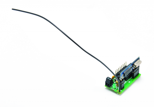
A receiving unit for UHF radio-controls, equipped with a breakout board RX and a microcontroller functioning as a decoder compatible with MM53200/3750 and HT12 codifications.
Here we are once again to talk about systems for radio-controlling, which are useful in various situations where you need to remotely activate/deactivate apparatuses and utilizes and it is impossible or un-convenient to use cables for commands. In this case, we are proposing a receiver compatible with so many hand-sized transmitters and keyring transmitter, functioning at 434 MHz and coded using a standard encoder; these transmitters are in the history of radio controls and to this day, they are still used in applications where command doesn’t have to be strictly exclusive. Unlike the vast majority of receivers, this is not based on hybrid modules but on a monolithic integrated radio receiver section mounted on a breakout board with the decoding implemented by one of the most cost-effective and simple microchip microcontrollers. Besides, this receiver, although has four channels, does not mount relays or TRIACs in order to switch power on the utilizers, on the other hand, it only provides TTL logic levels (0/5 V) to its outputs, in order to pilot possible power boards or relay boards such as those from the Arduino environment; the choice not to mount relays comes from our goal to create a really small circuit that can be easily integrated into a wide range of devices. It was actually the need to minimize dimensions which also imposed 5 V as circuit power, the voltage used by logic section and RF section, in order to avoid adding a voltage regulator, which would have increased encumbrance.

Circuit diagram
In order to understand what we are talking about, let’s take a look at the receiver circuit, based on an 8-bit PIC16F636 microcontroller, enclosed in a plastic 7+7 pin dip case; in this application, the micro gets the clock from the integrated oscillator, which is set by the firmware. We wanted to use the internal oscillator in order to limit the circuit’s encumbrance and use the pins only as I/Os. At first, we thought about using an even smaller PIC, e.g. a 4+4 pin case PIC, then for practical reasons (I/O number and necessity to integrate an EEPROM in order to save the codes of paired transmitters) we ended up choosing the PIC16F636.

The PIC has been reprogrammed in order to carry out three major functions: decoding the TTL signal provided by the radio receiving section; saving or confronting the codes and handle outputs at TTL level, which specifically corresponds to four of its pins, configured as output during its initialization.
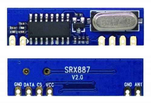
The radio receiver stage is all contained in an SRX887 module by NiceRF, which is a complete front-end tuned on either 315 or 434 MHz, as needed. This feature makes it a universal fit for radio controls, since all the older entrance controls, for instance, work at 300 MHz, because those were made before the regulation assigning the 433/434 MHz band to free use, civil radio controls.
This is a remarkable feature of this module, which allows to use it (and, subsequently, to use our radio control) to replace 300 MHz radio control receivers, which are hard to find nowadays, also because today it is really hard to find hybrid RXs working on 300 MHz, which would not respect the regulation.
The front-end and the rest of the receiver stages are contained in an integrated circuit soldered to the module and labeled SYN470R: it is a complete receiver with ASK/OOK amplitude demodulator (i.e. ON-OFF Keyed) integrating all the stages except for the antenna-tuned circuit, which must be added by putting an LC anti-resonant network before the RF input, coupled through a capacitor and a coil connected in parallel (thus realizing a C/L high pass filter). By using fixed components, we can do without creating and calibrating coils, making the creation of radio controls or data receivers easy and cost-effective.
The SYN470R integrated implements very useful functions: through the shutdown pin, we can turn off the device in order to, for instance, implement periodic power-on, to limit power consumption; on the other hand, thanks to the wake-up output pin, the integrated can send out a flag which indicates when the RF signal is on the input, in order to wake-up possible microcontrollers used as decoders, normally put into sleep mode in order to save energy.
The IF stage and the demodulator stage are totally integrated and do not require external components; the demodulator’s filter allows to select four bandwidths through the SEL0 and SEL1 pins, in order to set selectivity in various frequencies at will.
The SYN470R integrated includes two working modes: fixed-mode (FIX) and sweep-mode (SWP); in the first mode, it works as a narrow-banded superheterodyne receiver, while in the sweep mode, it fluctuates within a wider RF spectrum. As a consequence, Fixed-mode determines a better selectivity and sensitivity, while in Sweep-mode you can use to the receiver for tuning signals from cheap, non-quartz transmitters which frequency can largely deviate.
The sensitivity of receiving stage is very high, we are talking- 106dBm at 315MHz and -107dBm at 433MHz.
The module we used mounts the SYN470R preceded, at the RF input, by a Circuit tuned on 433 MHz, but you can find 315 MHz version; the onboard quartz is also calculated on such frequency.
Pin layout for our module is single-in-line (SIL) and provides six contacts, two of which are on the left and the other four on the right; connections are:
1) ANT = antenna input at 50 ohm;
2) GND = power ground and antenna ground;
3) VCC = 3,3÷5V power;
4) CS = it enables the module at logic level low and it puts it in shutdown at 1;
5) DATA = demodulator output (Data Out);
6) GND = power ground.
With that said, let’s analyze how our receiver works.
How it works
The module tunes in the RF signal converts it in frequency and extracts data from the IF, which is then squared in order to provide clean data on the output, i.e. the 5-pin (DATA); the U1 microcontroller acts as a decoder for signals coming from the transmitter unit, extracted by the U2. After the power-on-reset, RCO, RA2, RA1 and RA0 lines are initialized as push/pull outputs used in order to pilot lines 01 (channel 1) 02 (channel 2) 03 (channel 3) and 04 (channel 4) and therefore the devices to manage or to which send the commands. Each output is active at logic level 1.
In our remote control, all outputs work the same way, which is a monostable mode, i.e. impulse-based or bi-stable. We will explain later in this article how to decide. Monostable means that each output remains at logic level high as long as the related button on the transmitting unit is held pressed and the receiver receives a signal which is sufficiently strong to be decoded; when the button is released or radio connection between transmitter and receiver is lost, the output goes back to logic level low. Bi-stable means that at each reception a valid code switch states, therefore the first time it switches from zero to logic 1, the next time it goes back to zero and so on.
Still at initialization, RC4 is set as input used to receive data return from the output (5) pin of the U2 receiving module, which provides TTL impulses with a sequence equal to those produced by the transmitter’s encoder; RC5, on the other hand, is set as output and we need it to manage module power on in order to receive the signal. If you feel like tinkering with the PIC’s firmware, you can manage the activity duty cycle as you see fit, i.e. duration of power on and shut down.
Two lines are left to describe: RA3 is another push-pull output used to command the signal LED (LD1) of the various functioning phases for the receiver (learning, transmission identification); instead, RA5 is initialized as output with internal pull-up and we use it to read the P1 button used to manage self-learning and memory, according to the modes in a few paragraphs.
The receiver is powered by a 5 V (or 3.3 V) voltage coming from the + and – PWR leads, powering both U1 microcontroller and U2 radio module.
On the power line we have inserted a ceramic capacitor used to filter out impulsive disturbances received by connecting wires from the tension, and also possible power rested you, in case the receiver is integrated into an apparatus and powered by its power adapter.
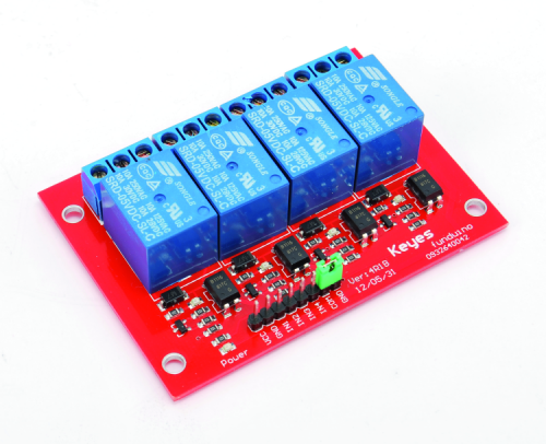
OUT1÷OUT4 outputs provide logic levels that can be used to send out commands to logic circuits, to the inputs of a microcontroller, or to a relay board such as the2846-RELAY4CH sold in our store.
The logic level command is useful if the remote control is integrated into a system that accepts them: for instance, something with a logics section on which we can act to turn it on and off, to adjust brightness, to turn a display on or off, but also to act in parallel on a logics section which is already controlled by other circuits, in order to implement a manual command alternative to an existing automatic one; this is the case with actuators piloted by a microcontroller or PLC which are managed by software following well-defined sequences and that we want to individually manage in manual mode, remotely.
The relay outputs, on the other hand, are optimal to manage utilizers functioning either at low or high voltage, in alternate or direct current, by maintaining galvanic isolation; this is the case with electronic locks, electrovalves, DC or AC electrical motors or transformers etc.
Download the code for Self-learning 4-channel receiver
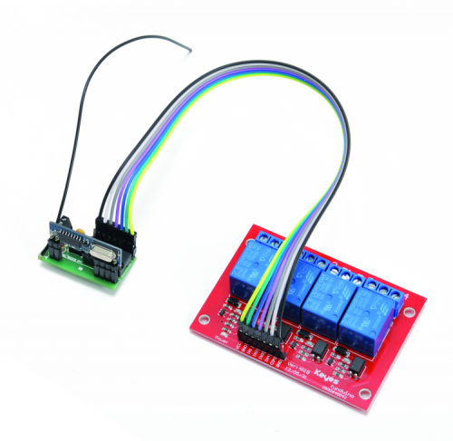
Relay interface
The figure shows the connection between receiver and relay board from our store and it is generally applicable to any similar relay interface board equipped with four TTL inputs.
The relay board we propose to complete the receiver is equipped with four relays with 5 V coil and exchange allowing to commute electric loads up to 240Vca and 10A; each relay is activated by bringing the command inputs to logic level high (from 1.6 to 5 Vcc), therefore the board is ideal to respond to logic levels provided by the PIC. The 4-relay board inputs are all opto-isolated, so that galvanic separation between board and command circuit is possible, as needed; each opto-isolator has the anode from the input emitter diode (pin 1) connected to the respective input through a current-limiting resistor and the cathode is in common with the LED’s cathodes of the other photocouplers and connected to the input’s COM lead. If you want to give up isolation, you have the bridge GND and COM contacts (since we don’t want isolation between command circuit and relays). For each relay there is a status LED placed on the board’s edge that will repeat the receiver’s status, therefore in case of pairing with a relay board we can avoid mounting channels status LEDs, which would be redundant and would determine excessive power absorption.

How it works
With that said, let’s move on and explain how the receiver works, when an RF signal is received and the signal is within the tuning range of the U2 module, this de-modulates the signal and provides the modeling component as output; the microcontroller is triggered by the events (logic level switch) on the 6-pin and its firmware analyzes the signal first, in order to verify its compatibility with the provided codes, i.e. the MM53200/UM3750 or UM86409 standard (binary 12-bit encoding, for a total of 4096 combinations, widely used in entrance gate controls) or HT12-compatible. The PIC16F636 is normally in standby and, when the first impulse arrives, it wakes up and analyzes incoming data, saving the strings in the RAM and then analyzing them to check if code and format are those expected; if this is not the case, procedure is abandoned, RAM is emptied and the PIC goes back in standby, waiting for new data. However, if the code and is the right one, it reads the byte containing the number of the channel to activate and it sends out a command to the corresponding output pin (CH1=RC0, CH2=RA2 and so on) and the LD1 status LED will light on; the corresponding output will switch from low-level to high-level, and then it’ll go back to zero once the transmitter’s established release button time is elapsed, that is from when the RF signal triggering the activation of the corresponding channel turns off.
The device is equipped with 4 outputs accessible from the pin-strip referred to GND’s Mike on the strip connector has the same pin-out of the 4Ch module (code RELAY4CH), in order to allow direct pin-to-pin connection. This way you can choose to implement in your own circuits or to pilot directly through the relays.
The STRIP connector is also equipped with 5 V output to power external devices, while the C contact is directly grounded.
This output is the reference pin many circuits.
Four outputs can be all managed either in bi-stable or monostable (the default setting when the circuit is first powered on), therefore it is not possible to choose at will which one to manage in bi-stable in which want to manage in monostable. You can pair only one remote code button to each output, this because it is, in any case, a note code and therefore easy to replicate on other radio controls.
In order to configure and set the code learning, you have to operate the P1 button.
To learn a radio control paired with output 1, press and hold the key, then, right when the LED turns on, release the key. Now, from the remote control, press and hold the key to memorize, and you can release the key when LD1 will start blinking quickly.
If you have to learn a second remote button to pair with output 2, the procedure is as above, but now you have to wait for the second blinking after the first one and so on and so forth for the third and fourth for the respective output.
Therefore, in order to make the pairing with the second output, press and hold the key, then wait for the second LED to turn on and release the key, now, on the remote control, press and hold the key to learn up until the LED on the receiver will start blinking quickly.
The same procedure can be followed for the third output (blinking 3 times) and the fourth output (blinking 4 times).
If you are in learning mode but you want to exit without saving any radio commands, you have to cut power off or, alternatively, press (short press or long press) the key, the LED blinks to signal that you are exiting the mode.
If you want to change monostable mode and switch to bi-stable, you have to press and hold the key until the LED will start blinking weekly for about 10 seconds.
From openstore

Is the PIC code available?
This article isn’t that old to not be able to get the source code.
I guess OpenElectronics is not a reliable source. No replies. Please, make the source available for this “Self-learning 4-channel receiver”.
You can download it from:
https://www.open-electronics.org/wp-content/uploads/2018/01/FT1294-RX_4ch.zip
Thank you very much.
Dear
Please your suggest
A company needs a receiver decoder module to decode
HT12 and as possible more of other fixed codes
to put this decoder on a new board for sliding gates
this company needs 1000 pcs and more per order
Thank you
Sotiris Salavrakos
Athens Greece