Connected to the USB port of a computer, it allows you to simultaneously control four dual-channel infrared receivers of the POWER FUNCTIONS LEGO® series through simple serial commands.
A few years ago LEGO®, manufacturer of the most famous brick in the world, introduced a system to make the most important sets dynamic through a very complete and versatile system of motors, wiring, controls, lighting and infrared remote controls, which it called “Power Functions”. Among the various components of this system, those that allow to introduce a more advanced game mode are the remote control and 2-channel receiver. In practice it is sufficient to have a battery pack, a receiver, one of the two IR transmitters (there are two types: one with two channels ON/OFF back and forth, and one always with two channels, back and forth with 7 levels adjustment for each direction of movement) and a receiver to be able to control one or two Power Functions units, which can be a motor, a servomotor or lights.
Each receiver has two channels, called blue and red, as well as an address that can be set from 1 to 4, so you can get up to 8 channels (1R, 1B, 2R…, 4R, 4B). The same address setting is present on the remote controls, so you can associate a specific remote control for each receiver.
This can be fine as long as you use one automated system at a time, which is the most common play mode among children who, in fact, do not use more than one train or one car at a time.
However, in recent years, a more evolved user group has gradually grown, mainly made up of adults (called AFOL, Adult Fan Of LEGO®) who make extremely complex dioramas, with considerable quantities of pieces (even more than a million in some cases) in which trains, carousels, windmills and anything else are integrated into a context and are in continuous movement.
At this level, using just one remote control is no longer enough, while using four at the same time, which you do anyway, is as feasible as it is inconvenient. Hence the idea to create a versatile control system, compatible with the IR Power Functions protocol, disclosed years ago by LEGO® itself with the precise request to limit the use to personal non-commercial activities, manageable through computers and simple commands.
In these pages we will describe the design of this device which, in compliance with the provisions of the parent company, will not be offered for sale in any form. As far as the components necessary for its realization are concerned, they are easily available at low prices, at open electronics In fact, the know-how necessary to realize this object is provided free of charge without any profit, but the hardware components to assemble it are needed.
Well, whether you are AFOL or not, if we have succeeded in intriguing you, in the next pages you will discover how to realize this project with which you, together with your children, can have fun.
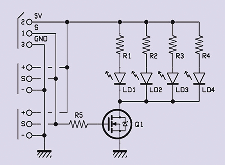
Circuit diagram

The circuit is very simple and essential, based on a small PIC12F683 (U2) microcontroller that contains the decoding code of the serial commands and directly controls the pilot transistor for the infrared LEDs through the GPIO1 line (pin 6) and the activity LED through the GPIO0 line (pin 7).
Pins 2 and 3, which can perform different functions, have been configured as input and output for a high frequency quartz; a 16 MHz quartz is connected to them for the timing necessary to generate the correct infrared pulse train.
Finally, serial communication is realized with a complete FT782 USB-Serial module (U1) whose TX and RX lines are connected respectively to pin 4 (Vpp/Reset/GPIO3, which if not used as reset can be programmed as input) and pin 5 (GPIO2).
The necessary power supply to the micro and infrared transmitter is obtained directly from the USB port of the PC through the FT782 card which must be set to deliver directly the 5 V coming from the USB port through a special solder jumper.
Firmware
The flow chart, shown in Fig.1, is very simple: after initializing the registers, variables and I/O lines, the system waits for a serial character. When it receives it, it enters the main loop where it continues to wait for serial characters which, in this case, will generate some kind of reaction.
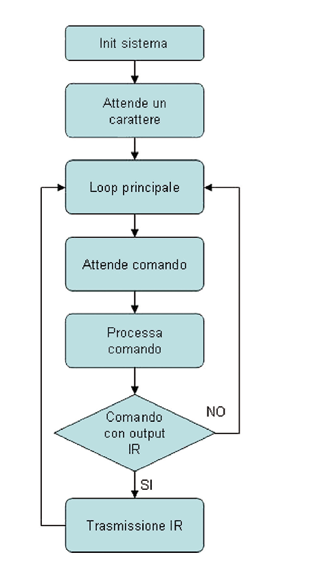
Fig.1
When a character is received, valid or not, it follows the process of this command which can end with a transmission of an infrared code or a saving in EEPROM or a restart, according to what is foreseen in the command set.
At the end of the command execution, the program returns to the main loop and waits for a new command to be executed.

Usage
First, connect the device to a free USB port on the computer: the life LED on the board flashes twice a second indicating that it is active. Newer operating systems will probably automatically recognize the FT782 serial USB converter because it is based on a widely used FTDI chip. Others may require the driver externally. If this is the case, it can be downloaded from the site
www.ftdichip.com/FTDrivers.htm. From this point we assume that the driver is installed correctly. The next step is to open the device management window (Fig. 2) and identify the COM PORT that has been assigned to our serial USB converter: in this case it is COM 12. Once this is done, you can close the window by clicking on the X at the top right.
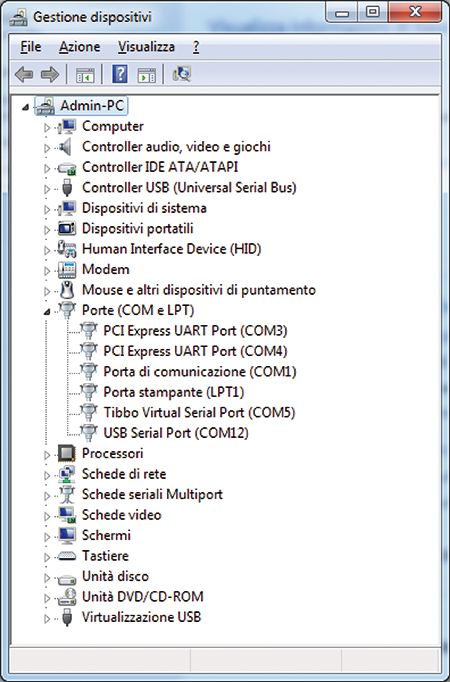
Fig. 2
Any terminal emulator is then started: in this case we use Hyper Terminal which, immediately after starting, asks to assign a name and an icon to the new connection that is being created; here it has been called “Power Functions USB” (Fig. 3). It is confirmed by clicking on OK. A new window appears, Connect to” (Fig. 4), in which the program asks some further parameters of configuration, parameters that we will ignore to go directly to choose “Connect using COM12” (in our case the COM is the 12); once again we confirm clicking on OK.
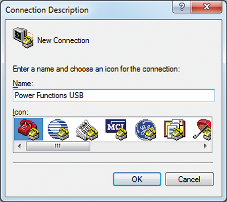
Fig. 3
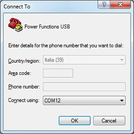
Fig. 4
A last window opens in which we define the connection properties: our device communicates with Hyper Terminal at 38.400 bps per second, with 8 data bits, no parity, 1 stop bit and no flow control (Fig. 5); it is also possible to choose, during compilation, between four different baud rates (4.800, 9.600, 19.200 and 38.400). Confirm one last time by clicking on OK. At this point the main communication screen appears, where you can see the message “Hit a key!” with a flashing exclamation mark: with this message the device invites you to press a key to continue.
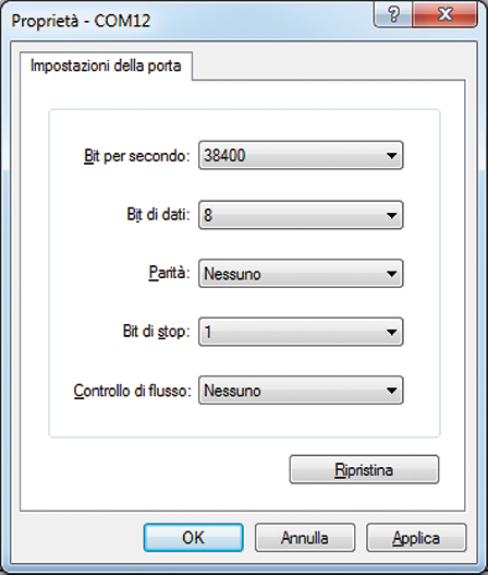
Fig. 5
Pressing a button sends the message “Ready. M/m: Menu” (Fig. 6) to indicate that the remote control is ready and that pressing the “M” key in upper or lower case” calls up the command menu. The activity LED now blinks once every two seconds.
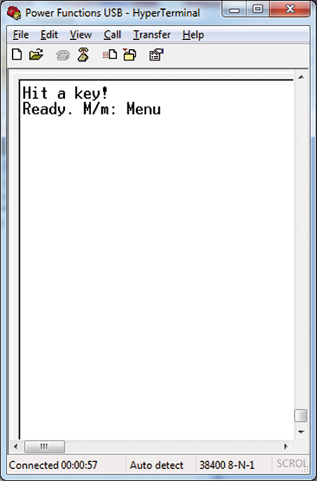
Fig. 6
Keep in mind that all commands recalled by a letter are executed with both uppercase and lowercase letters (they are not case-sensitive). Type M to recall the menu of available commands (Fig. 7) and see them one at a time.
“V” recalls the program version which, in this case, is the 1.50 serial command: this command has no effect on IR transmission.
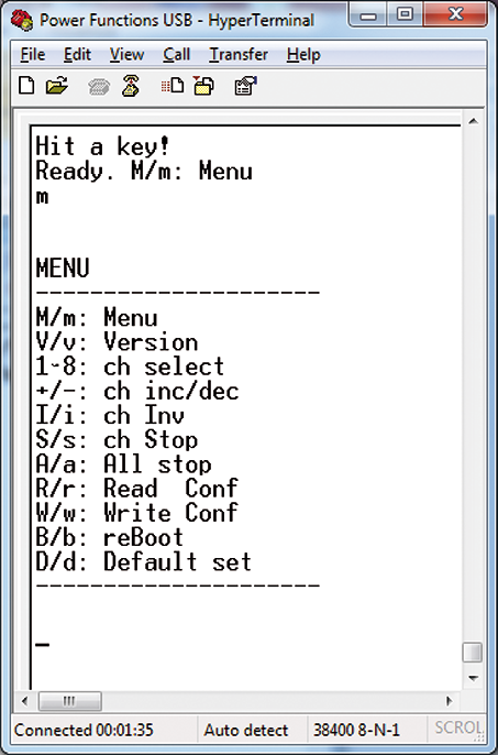
Fig. 7
Use keys 1 to 8 (Fig. 8) to select the channel you wish to control. Once a channel has been selected, it remains stored until a different channel is selected; the selection of a channel still does not generate any transmission.
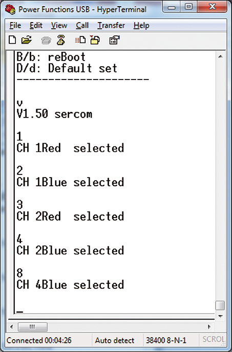
Fig. 8
Use the “+” and “-” keys to send the infrared command (Fig. 9). According to the Power Functions protocol in “Single output” mode, there are 7 speed levels in both directions, plus one brake stop and one neutral stop (not used here). The device always responds with the echo of the received character, the selected channel with its variation (e.g. CH8+, CH6+…) and the current condition of the channel, for example:
CH8:N,>1,01,01110001

Fig. 9
Which should be read this way: “channel 8 works in normal mode (i.e. not reversed as direction), has received a command to NEXT at speed 1 and the parameter passed to the infrared driver is 01. The binary channel string shows the address in the high nibble and the value of the speed and direction in the low nibble. The field “B0” means “Brake 0”, i.e. stop braked.
The message ends with “IR code sent” as confirmation of successful transmission.
With the I button (Fig. 10) you can communicate to the device to invert the direction of movement relative to the command sent, this option is foreseen both by the protocol and by the remote controls and very useful when you are not able to establish a priori what the direction of movement will be. Also in this case we have the echo of the command followed by the variation and the channel that received it. The channel inversion determines the transmission to all channels of the stop command with brake, in order to avoid that reversals of motors already moving can cause kickbacks if not certainly dangerous.

Fig. 10
In Fig. 11 you can see how the speed parameter corresponds to 15, 14, 13… for the lowest speeds backwards and decreases with increasing speed, this is because the protocol foresees the position of BRAKE at %xxxx1000 while %xxxx0111 and %xxxx1001 (immediately before and after BRAKE) correspond to the highest speeds. Strange as it may seem, the Power Functions protocol has been implemented in this way. Finally, let’s see the last commands, visible in Fig. 12 and Fig. 13. Any command that is not part of those recognized generates the “Wrong” response. The “R” command allows you to read the channel configuration. In this case on the DIR line we see that channels 1 to 7 are normal and 8 is inverted, and on the Now line, channels 1 to 7 are stopped, while channel 8 travels forward, with inverted direction, at speed 3 of 7.
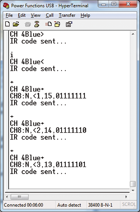
Fig. 11
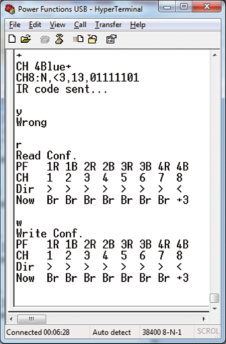
Fig. 12

Fig. 13
The “W” command allows to save in EEPROM the inversion configuration seen through the “R” command. The “B” command allows you to restart the device from the beginning, without changing any configuration and is useful when, while experimenting, you do not know in which situation you have stopped.
The “D” command finally loads and saves the factory configuration (default). At this point, if you want, you can close Hyper Terminal, which will warn you that you are currently connected to the device and if you want to save the Power Functions USB configuration: if you do so, the next time you restart Hyper Terminal you can directly recall this configuration instead of repeating what you saw in Fig. 3 to Fig. 5. If you have previously saved a configuration with the same name, Hyper Terminal will ask you if you want to overwrite the new configuration to the previous one.
The LEGO® Power Functions system
It is a very complete game system, rather technological although within the reach of a child, designed with high safety standards, with a wealth of accessories that we will not detail here, but rather describe those elements used to explain the operation of our remote control.
Generally speaking, the whole series of Power Functions accessories can be divided into the macro categories listed below (Fig. 14).
- Battery packs: there are three types, one with stylus batteries (in the table), a smaller one with miniature batteries, and one with rechargeable battery.
- Portable remote controls: two types, one ON OFF forward backward, and one forward backward adjustable to 7 speed levels (both in the table).
- The IR receiver, one type (in the table).
- Motors (of different sizes and shapes), servomotor and lights, in the table.
- Accessories such as extension cables, battery charger and sensors (not shown).

Fig. 14
Table1
The system of our interest is the one proposed in Fig. 15, which shows a 6 AA batteries pack powering an IR receiver to which two motors are connected; everything is managed by a remote control with two sub-channels.
Each receiver and each remote control can have address from 1 to 4 (selectable by cursor) and each address is able to manage two different sub-channels called Red and Blue. Each remote control also has a selector to set whether the channel should work directly or inverted. The larger remote control, then, also has two red square buttons that determine the immediate stop with brake of the devices associated with that subchannel. There are no limits on the number of receivers that can be used, while the address limit is 4, with two sub-channels, in total 8 channels.
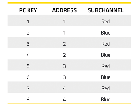
Now, in order to uniquely control each channel by selecting it with a single button from 1 to 8, the button/channel/subchannel correspondence visible in Table 1 has been created. This correspondence has also been inserted in the responses to channel selection and read/write of the current status.

Fig. 15
IR coding
The Power Functions system has been in existence for several years and has received an excellent consensus among both children and AFOL, so much so that LEGO®, in 2008, decided to make the format of the IR protocol in the public domain as long as it was non-profit.
When this article was written, the PDF document was available at the following links:
• www.philohome.com/pf/LEGO_Power_Functions_RC.pdf;
• storage.technicbricks.com/Media/2010/TBs_20100304_1/LEGO%20Power%20Functions%20RC%20v120.pdf;
• github.com/jurriaan/Arduino-PowerFunctions;
• docplayer.net/24969822-Document-title-lego-power-functions-rc-init-gmu-version-date-version-1-20.html.
It was probably once available on the LEGO® website, but now it seems to have been removed.
In any case, this document explains exactly how to generate the IR transmission timings and, if you are interested in decoding them, also the way and times to be included in the tolerance check, as well as the bits to be transmitted and the various transmission modes. Let’s see together the parts of our interest: the plot sent to the infrared section consists of 18 bits transmitted at 38 kHz, classified in Start, Nibble from 1 to 4 and Stop. Each bit (or group) assumes a meaning depending on the chosen mode of operation. In principle we have this situation (Fig. 16):
-
Start and stop are the synchronism signals;
-
Toggle (1 bit) reverses its status at each transmission;
-
Escape (1 bit) sets the PWM mode (ours) or one of the other modes (not analyzed here);
-
Channel (2 bit) selects channel 1 to 4;
- Address (1 bit) in our use selects the red or blue channel;
- Mode (3 bit) defines the mode of operation;
- Date (4 bits) sets the value to pass to the channel;
- LRC (4 bit) is the checksum, obtained with the formula 0xF xor Nib1 xor Nib2 xor Nib3.
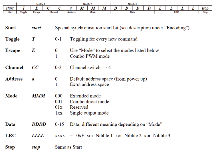
Fig. 16
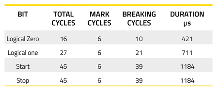
Once the bits are defined, let’s see how they should be generated: referring to Fig. 17, a bit always consists of a “MARK” and a pause. The MARK is constant and consists of 6 pulses with a 50% duty-cycle, at a rate of 1/38,000 seconds, i.e. a “high-low” cycle lasts 1/38,000 seconds (26.31 µs). So with 50% duty-cycle, high and low each last 13.16 µs. A MARK therefore lasts 6 cycles.
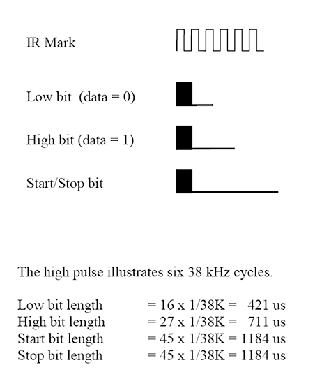
Fig. 17
From this and the specifications in the manual we can derive what is shown in Table 2.
Table 2
Once the transmission timings have been established, all that remains to be done is to see how the transmission of our interest is structured, which is called “Single Output Mode”. Let’s start from the first bit, that is the toggle, currently 0; since it is managed, it must invert its state at each transmission.Escape, instead, must be set to 0. The channel bits are used and have a value from 0 to 3, equal to addresses 1 to 4. The bit address that is currently not used should therefore be left at 0. The second bit of the nibble2 must be left fixed at 1. Mode, in our case, must be fixed at zero because we are interested in the 7-level PWM mode. The output bit follows, which selects the red or blue channel (0 always corresponds to red). All the nibble3 contains direction and speed of the selected channel, with the values shown in Fig. 18. The 4 checksum bits follow, calculated according to the formula already seen above. The stop bit closes the plot.
What explained above can be seen in the source list extract (Listing 1) related to the transmission encoding.
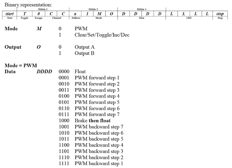
Fig. 18
Listing 1
Listato 1
IR_TRANSMIT:
for REPEAT_IRTX = 0 to 2
for CH_IRTX = 0 to 7
IRTX_RT = CH_IRTX_VAL(CH_IRTX)
IRW = 0
toggle TOGGLE_BIT
‘ inverte toggle bit.
if TOGGLE_BIT = 0 then
low IRW.0
low nib1.3
else
high IRW.0
high nib1.3
endif
‘ bit escape fisso a 0
low IRW.1
LOW NIB1.2
‘ imposta bit 2 e 1 indirizzo
if IRTX_RT.6 = 0 then
low IRW.2
low nib1.1
else
high IRW.2
high nib1.1
endif
if IRTX_RT.5 = 0 then
low IRW.3
low nib1.0
else
high IRW.3
high nib1.0
endif
‘ bit “a” fisso a 0
low IRW.4
low NIB2.3
‘ bit “5” fisso a 1
High IRW.5
high NIB2.2
‘ modo PWM con bit 6 fisso a 0
low IRW.6
low nib2.1
‘ imposta bit 0 indirizzo canale
if IRTX_RT.4 = 0 then
low IRW.7
low nib2.0
else
high IRW.7
high nib2.0
endif
‘ imposta i bit di PWM
if IRTX_RT.3 = 0 then
low IRW.8
low nib3.3
else
high IRW.8
high nib3.3
endif
if IRTX_RT.2 = 0 then
low IRW.9
low nib3.2
else
high IRW.9
high nib3.2
endif
if IRTX_RT.1 = 0 then
low IRW.10
low nib3.1
else
high IRW.10
high nib3.1
endif
if IRTX_RT.0 = 0 then
low IRW.11
low nib3.0
else
high IRW.11
high nib3.0
endif
‘ calcola il checksum
CHKSM = $f ^ NIB1 ^ NIB2 ^ NIB3
if CHKSM.3 = 0 then
low IRW.12
else
high IRW.12
endif
if CHKSM.2 = 0 then
low IRW.13
else
high IRW.13
endif
if CHKSM.1 = 0 then
low IRW.14
else
high IRW.14
endif
if CHKSM.0 = 0 then
low IRW.15
else
high IRW.15
endif
‘chiama tx prima stringa
toggle vita
call TX_START_STOP
for SCAN_BIT = 0 to 15
if IRw.0 = 1 then
call TX_HIGH
else
call TX_LOW
endif
IRw=IRw>>1
next SCAN_BIT
call TX_START_STOP
pause 1
next CH_IRTX
next REPEAT_IRTX
low VITA
gosub MSG_IRSENT
gosub MSG_CRLF
return
‘ Routine per scrivere start-stop, alto e basso.
TX_START_STOP:
pausa = T_STST
goto TX_GO
TX_LOW:
pausa = T_LOW
goto TX_GO
TX_HIGH:
pausa = T_HIGH
goto TX_GO
TX_GO:
for NPULS_IRTX = 0 to NUM_PULS
high IR_OUT
pauseus 10
ASM
nop
nop
nop
nop
nop
nop
nop
nop
nop
nop
endasm
low IR_OUT
pauseus 9
ASM
nop
nop
nop
endasm
next NPULS_IRTX
pauseus pausa
return
Firmware
Let’s finish with the description of the program: when called, the routine performs three times the transmission of the command to all channels. Note that it has been chosen to always command them all at the same time, even if what varies is only one at a time, so you can always be sure that the operating status on all is always up to date. The routine performs two nested for/next cycles. The first (innermost), from 0 to 7, selects the channel to be controlled, while the second, more external, repeats the transmissions. At each step, the conversion wheel receives the channel to command, checks the bits one by one and always one by one it goes to set the bits of the word IRW variable, which contains all the bit packet seen in the paragraph of the protocol description.
The timings were obtained experimentally by inserting NOP cycles (which at 16 MHz determine a temporary suspension of operation for 5 clock cycles, i.e. 0.3125 microseconds) in two sections of ASSEMBLER code (see routines TX_START_STOP, TX_LOW and TX_HIGH).
Conclusions
The project described here is the ideal complement to a LEGO® POWER FUNCTIONS system and allows, connected to the USB port of a Personal Computer, to control four dual-channel IR receivers of the POWER FUNCTIONS series. It can therefore replace one or more remote controls, or become a useful test and debugging tool for LEGO® systems and lends itself to numerous developments. The possibility to choose whether to combine it with a simple IR LED or a three-LED module allows it to be adapted to all conditions and various range requirements.
From openstore
