It detects stationary and moving people just like a PIR, but it can do that also behind doors and thin walls, by taking advantage of the Doppler effect.
The detection of people, animals and hot bodies in general has been done for years using passive infrared radars, also known as PIR, which work by placing a pyroelectric sensor, so a heat sensor, behind a Fresnel lens, which has the ability to focus on just one point the infrared rays coming from the frontally detected heat, emitted by moving objects within a certain angle.
PIR sensors cover a wide array and variety of applications and represent by now a low-cost solution to protect ourselves from home invasion, automatically activate utilizers when moving people are detected etc., although they have the limitation to be able to detect only whatever can be seen: they cannot detect, even at a short distance, people moving behind doors and windows, so if we employ them in a home security system, they will only be activated when the intruder is already inside the room where the sensors are installed.
In order to have a preemptive protection, we can make use of radiofrequency sensors and, to be precise, microwave sensors, because they can detect people behind doors and even walls as long as they are not too thick or made of reinforced concrete or metal, or walls containing metal plaster reinforcement grids (for bladder walls) or cavity for sliding doors such as Scrigno.
Microwave detectors can be monostable (like ours) or bistable, meaning they are mounted as a couple one in front of the other; in this case, emitter and receiver are placed in separate units. Monostable units define a detection area based on the microwave beam they emit and the coverage can reach up to 300÷400 linear meters, besides, we can configure it to the RF beam to adapt to special situations, so we can lengthen it or shorten it, make it smaller (in order to have a longer beam) or make it wider (which means a shorter distance but a bigger angular coverage).
On the other hand, a bistable microwave detector offers a wider detection era, even up to 1 km, but is very delimited; its applications are on external wall installations, for instance when we want to protect our garden entrance. Bistable sensors are also more prone to false alarms because the emit frequencies, activating and deactivating them in rapid cycles, followed by deactivation of the receiver. The unit uses these time intervals in order to detect movement checking object placement at different times.
In these pages, we propose a project for a microwave detector based on a dedicated module, in breakout board format.
Circuit diagram
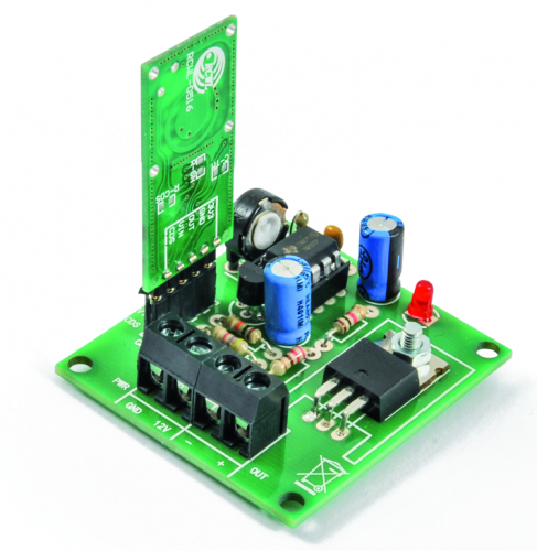
Our sensor is basically a radar based on the Doppler effect, composed of an electronic section described by the circuit diagram, in which we’re going to insert the sensor’s breakout board. The latter is based on the RCWL9196 integrated that interfaces with a radar cavity made with an MMBR941M BJP Colpitts oscillator, which takes advantage of the PCB tracks to obtain the capacities and inductors needed to function properly. Fig. 1 shows the circuit diagram for the breakout board, which can be seen in Fig. 2.
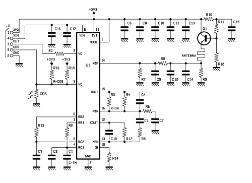
Fig. 1
The Doppler effect is a physical phenomenon for which the frequency perceived by someone who listens to a sound wave emitted by a source that is moving in relation to the observer themselves changes its commission value; the typical example is an ambulance, which siren changes tone (it goes lower) as the ambulance goes away, or the sound of a moving train.
The fact is named after Christian Andreas Doppler, who was the first to notice and document it; later on, Hippolyte Fizeau found out that the same effect takes place with electromagnetic waves emitted by a moving transmitter antenna, detected by a fixed receiver.
The Doppler effect is explained considering that as the sound source moves away, the wavelength increases, sound speed being equal.
With that said, let’s move on to the breakout board employed in the project, used to compose a microwave module with a planar antenna created on the PCB and containing an oscillator, a RF mixer and a discriminator detecting the radio wave alteration caused by the presence of a moving person intercepted in the area covered by the sensor itself.
The RCWL9196 integrated contains the mixer and the discriminator for the RF signal and provides, towards its VO pin, which ends on the OUT terminal of the breakout board on which it is mounted, a logic signal whenever there is a detection; specifically, OUT is normally at logical level low and switches from zero to logical 1 (3.3 V) whenever a moving object is detected, then goes back to zero.
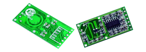
Fig. 2
The module is connected to the circuit through a series of pads on which it is going to be soldered and it is powered by the Vin terminal (after the D1 protection diet protecting from polarity inversion) and GND, while it provides its logical output signal through the OUT terminal; the output signal of the breakout board pilots the base of a NPN transistor used as level adapter and inverter, therefore configured as common emitter, which collector, when OUT goes up to 3.3 V (logical one), grounds the trigger pin (2) of a 555 timer integrated used here in its re-triggerable monostable multi-vibrator configuration. This means that the 555 will provide a constant duration impulse, however, when it is triggered again for the corresponding time elapsed, temporization will start over.
Therefore, the purpose of this stadium is to extract an output impulse of defined duration and adjustable, through the R5 trimmer, anytime the microwave sensor is activated and provides a high logical level impulse. The duration (t) of the impulse is roughly equal to:
t = 1,1 x C1 (R1+R5)
RCWL9196
And since R5 is a trimmer connected as a rheostat, we can adjust the time based on our needs, from a minimum of 0.25 to a maximum of 24 seconds. In the formula, t is expressed in seconds when C1 is expressed in microfarads and resistance in megaohms.
The functioning of the re-triggerable monostable can be explained by considering that there are two comparators inside the 555 that take the voltages extracted from a resistor ladder divider as reference; the divider is composed of three identical resistors, providing around 2/3 of the power voltage (pin 8) to the top comparator (which non-inverting input is connected to THRESHOLD, pin 6) and around 1/3 to the bottom comparator, which inverting input is connected to pin 2 (TRIGGER). The two comparators pilot a RS flip-flop, which has two inputs conditioning the output status Q: the output of the first comparator pilots the R input (which brings output Q to zero when brought to logical 1) and the bottom comparator’s output controls the flip-flop’s S input, which forces output Q to logical 1 when brought to 1 itself. The RS flip-flop inside the 555 also has a complemented (/Q) output which status is the opposite of Q and pilots an NPN transistor configured as an open collector, common emitter, which collector ends on pin 7 (DISCHARGE) of the integrated. The output Q is instead brought to pin 3, which is the output for 555, used to pilot an enhancement-mode, N-channel MOSFET configured as open-drain for switching an electric load under direct current.
In standby, i.e. when the RF sensor module’s output is at level low, T1 transistor is interdicted and the C1 capacitor charges up through the R1-R5 series; when the voltage on its plates is more than two thirds of the 555’s power, the flip-flop is reset, so that its output goes to logical 0 and pin 3 goes in the same state. The circuit stays like this until there is a higher level impulse on the OUT terminal, which sends the T1 transistor into saturation and discharges the C1 capacitor; said condition switches the 555’s bottom comparator, which output activates the flip-flop’s SET, bringing pan 3 to logical level high, maintaining the situation until the C1 capacitor will be charged enough to bring back pin 62 voltage higher than 2/3 of power voltage.
C1 can recharge when OUT goes back to logical zero, then T1 goes into interdiction again; if, before set time (t) is up, the RF sensor emits a new impulse, T1 goes back into saturation and almost instantaneously discharges the electrolytic, setting the timer back to zero and postponing the permanence of pin 3 of the integrated circuit to level high) and the turning off of the load, which can be a relay to pilot 230Vca utilizers or a lightbulb, an acoustic device or something else working under low-voltage, direct current. (fig.3)

Fig. 3
The low voltage must be the same as the circuit’s power voltage, so we have no problems managing utilizers at 5 and 24 Vcc.
The current outputted by the MOSFET takes also into account the dimension of the printed circuit tracks and it maxes out at around 500 mA.
The entire circuit is powered through the + and – PWR terminals and the workload power (i.e. the MOSFET static switch) is taken in parallel to those; on that hand, the voltage going to the RF sensor module in the monostable stage based on the 555 goes through the D1 protection diode, preventing damages to the electronics in case you apply wrong polarity voltage by mistake.
Components list for module RCWL-0516
C1: –
C2, C3, C18: 10 nF ceramic
C4, C8, C10, C11, C13: 100 nF ceramic
C15, C16, C17: 100 nF ceramic
C5, C6, C7: 22 pF ceramic
C9: 1 nF ceramic
C12, C14: 33 pF ceramic
R1, R10: 100 ohm
R2: 10 kohm
R3, R16, R18: –
R4, R13, R14, R15, R17: 1 Mohm
R5, R6: 22 kohm
R7: 56 kohm
R8: 1 kohm
R9: 220 ohm
R11: 4,7 kohm
R12: 2,2 kohm
Q1:BFR520
U1:RCWL-9196
J1: 5 way male strip
Support board
C1: 47 µF 63 VL electrolytic
C2: 100 nF ceramic
C3: 100 µF 25 VL electrolytic
R1, R2: 4,7 kohm
R3: 10 kohm
R4: 1 kohm
R5: Trimmer 470 kohm MV R6: 220 ohm
LD1: LED 3 mm red
D1: 1N4148
T1: BC547
U1: NE555
Q1: IRF540
Miscellaneous:
– 2-way terminal block
5 mm (2 pz.)
– 4+4 base
– 5-way female strip
– 5-way, 90° mail strip
– 10 mm 3 MA screw
– 3 MA nut
– Printed circuit
S1283 (44 x 47 mm)

Conclusion
In addition to the circuit described in these pages, the RCWL-0516 can be coupled with Arduino or Fishino; in this case (as you can see from Fig. 3) it can be used to automatically open doors and motorized gates, to automatically turn on lights in rooms or passage points, but also to create security alarm systems.
We could also take the analogue output of the RCWL-9196 and read it with one of Arduino’s analogue inputs, in order to have an indicative measurement of the distance of the detected person, based on the signal amplitude.
From openstore

[…] Microwave Presence detector works using Doppler Effect – [Link] […]
[…] Read more: Microwave Presence Detector Works Using Doppler Effect […]
I have gone through your article regarding Presence detector with microwave. It is excellent way of description but I want to have details of your circuit board if you can help me please.