
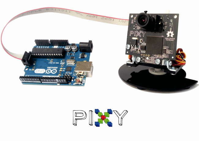
Here we present our first tests with the Pixy camera, a device capable of detecting the colour of the objects, and to track their position.
Until a short time ago, it was really difficult to develop applications able to take advantage of artificial vision algorithms, and most of all by using systems with limited hardware resources.
Luckily, however, things have changed now: in addition to the various open source frameworks that help developers to easily implement even the most complex algorithms, complete peripherals are spreading, be it for the hardware part (providing the acquisition of images coming from the outside world), or for the software part (able to analyze and read such images). With such peripherals it is possible to create applications provided with artificial vision, in a really simple way.
It is enough to use these devices coupled with a microcontroller or with a prototyping board, such as Arduino, for example. These peripherals deal with the whole part concerning calculations, thus freeing hardware resources of the device they’re connected to, and exchanging only the essential information with it. In this manner anyone will be able to create applications capable of observing and analyzing the surrounding environment, in an extremely simple way.
In this article we will deal with the examination of the operation of the Pixy camera, an open source device capable of locating the position of objects, and to communicate the coordinates to Arduino or other microcontrollers.
INSTALLING THE NECESSARY COMPONENTS
In this post we will use the pan/tilt module as well: it is an accessory that allows Pixy cameras to follow the changes in the objects position.
Once all the hardware material has been retrieved, it is possible to download the management software, that is needed to easily set up the objects that the Pixy camera will have to recognize, and to debug the same. The software is named PixyMon and it is possible to retrieve it at the following address: http://cmucam.org/projects/cmucam5/files.

PIXYMON: THE MANAGEMENT SOFTWARE
Once the installation procedure of the software is complete, we may connect the Pixy Camera to our PC. On the back side of Pixy a Mini-USB type connector can be found; let’s get the suitable cable then and connect the video camera to our computer.
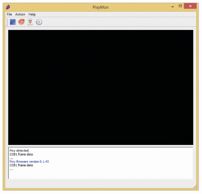
Once the connection procedure is complete, it is possible to open the PixyMon program.
To ensure that the black area is replaced by the images from the video flow, it will be enough to click on the steak-shaped icon, placed up and on the left. If the images turn out to be too dark, it is possible to modify Pixy’s brightness. From the “Configure Parameters” menu (that can be accessed by clicking on the cog-shaped icon), we may modify the Brightness parameter. By increasing this parameter, images will be brighter, vice versa they will be darker. Pixy is capable of increasing or reducing the brightness automatically, however if the object to detect is too dark or too bright, it will be necessary to adjust the brightness value.

At this stage, we may make Pixy learn the object to detect. The device will recognize the item depending on his colour, thus it is important that it is as much as possible homogeneous. Once this premise has been made, we may start the learning phase. We have to place the object to detect before the camera lens, whereupon, from the Action menu, we have to select “Set Signature 1…”. Once this has been done, we have to highlight the body of the object, by keeping the left mouse button pressed. By releasing the mouse button, the video camera will memorize the item’s colour.

It is also possible to memorize the item without having to use PixyMon. By pressing the button placed on the superior side of the video camera, and by respecting the appropriate sequence, it is in fact possible to memorize the object placed before the camera lens. This method is however more complex and we will see it when we will connect the video camera to Arduino.
Independently from the mode used, Pixy is capable of memorizing up to seven different objects. The video camera will keep them in memory until they are deleted or overwritten. Thus disconnecting Pixy from the PC or from his power source will not cause the deletion of the learned items. The PixyMon management software allows us to test the pan/tilt system as well; to do so it is needed to memorize at least an object, whereupon it will be enough to click on “Run pan/tilt demo” from the Action menu. We will then see the pan/tilt module’s servos that will move the video camera, so to frame on the memorized object. It is possible that during the demo of the pan/tilt system, the video camera is disconnected from the PC many times. This happens if you possess a low quality USB cable or if the PC we’re using has a sub-optimal USB ports management.
CONNECTING ARDUINO

It is quite simple to connect Pixy to Arduino: you just need to pick up the flat cable contained in the video camera package, and to connect the biggest terminal to the back side of Pixy (the connector on the back prevents from getting it in the wrong way), and finally to connect the smaller terminal to Arduino. Make attention to the orientation of the red cable. At this stage we may connect Arduino to our PC and load our first sketches.
It is possible to download the libraries and the sample sketches from the following link: http://cmucam.org/attachments/download/ 1065/arduino_pixy-0.1.5.zip.
To import the libraries it is needed to open Arduino’s IDE, and then, from the Sketch menu, select the “Import Library…” entry, then “Add Library…” and finally select the folder in which the files you just downloaded from the zip archive are kept.
This operation will load the sample sketches as well. To see their code it is enough to click on the File menu, then on Examples and lastly, on the Pixy submenu.
FIRST SKETCH: HELLO WORLD
//
// begin license header
//
// This file is part of Pixy CMUcam5 or “Pixy” for short
//
// All Pixy source code is provided under the terms of the
// GNU General Public License v2 (http://www.gnu.org/licenses/gpl-2.0.html).
// Those wishing to use Pixy source code, software and/or
// technologies under different licensing terms should contact us at
// cmucam@cs.cmu.edu. Such licensing terms are available for
// all portions of the Pixy codebase presented here.
//
// end license header
//
/*
06.04.2014 v0.1.3 John Leimon
+ Now using pixy.init() to initialize Pixy in setup().
*/
#include <SPI.h>
#include <Pixy.h>
Pixy pixy;
void setup()
{
Serial.begin(9600);
Serial.print(“Starting...\n”);
pixy.init();
}
void loop()
{
static int i = 0;
int j;
uint16_t blocks;
char buf[32];
blocks = pixy.getBlocks();
if (blocks)
{
i++;
if (i%50==0)
{
sprintf(buf, “Detected %d:\n”, blocks);
Serial.print(buf);
for (j=0; j<blocks; j++)
{
sprintf(buf, “ block %d: “, j);
Serial.print(buf);
pixy.blocks[j].print();
}
}
}
}
Overall, the sample sketches are four. The first sketch is named hello_world, and the source can be seen in Listing 1. As a first thing, the libraries are imported, as required to create the correct communication between Arduino and the video camera. Later, a Pixy-type object is created, and it is initialized by the setup function.
The serial communication with the PC is also set up with this function: in this manner we will be able to see the various debug messages. The getBlocks() method, recalled in the body of the loop function, is needed to count how many memorized objects are before the video camera lens. The method returns an integer, whose value is given by the total number of recognized objects. For each identified object, it is possible to retrieve a series of information pieces, such as his coordinates or his dimensions (in pixels), for example.
The following for cycle is needed for this purpose exactly. Each recognized item is automatically saved in the array blocks of the Pixy object; the pixy.blocks[j].print() instruction then allows us to access the identified object and to print the relative information. In addition to the print method, each object also has the following attributes: x, y, width, height and signature. This last attribute contains the number of the identified object, varying from 1 to 7, depending on the order the item has been memorized.
SECOND SKETCH: PAN/TILT
//
// begin license header
//
// This file is part of Pixy CMUcam5 or “Pixy” for short
//
// All Pixy source code is provided under the terms of the
// GNU General Public License v2 (http://www.gnu.org/licenses/gpl-2.0.html).
// Those wishing to use Pixy source code, software and/or
// technologies under different licensing terms should contact us at
// cmucam@cs.cmu.edu. Such licensing terms are available for
// all portions of the Pixy codebase presented here.
//
// end license header
//
#include <SPI.h>
#include <Pixy.h>
#define X_CENTER 160L
#define Y_CENTER 100L
#define RCS_MIN_POS 0L
#define RCS_MAX_POS 1000L
#define RCS_CENTER_POS ((RCS_MAX_POS-RCS_MIN_POS)/2)
class ServoLoop
{
public:
ServoLoop(int32_t pgain, int32_t dgain);
void update(int32_t error);
int32_t m_pos;
int32_t m_prevError;
int32_t m_pgain;
int32_t m_dgain;
};
ServoLoop panLoop(500, 800);
ServoLoop tiltLoop(700, 900);
ServoLoop::ServoLoop(int32_t pgain, int32_t dgain)
{
m_pos = RCS_CENTER_POS;
m_pgain = pgain;
m_dgain = dgain;
m_prevError = 0x80000000L;
}
void ServoLoop::update(int32_t error)
{
long int vel;
char buf[32];
if (m_prevError!=0x80000000)
{
vel = (error*m_pgain + (error - m_prevError)*m_dgain)>>10;
//sprintf(buf, “%ld\n”, vel);
//Serial.print(buf);
m_pos += vel;
if (m_pos>RCS_MAX_POS)
m_pos = RCS_MAX_POS;
else if (m_pos<RCS_MIN_POS)
m_pos = RCS_MIN_POS;
//cprintf(“%d %d %d\n”, m_axis, m_pos, vel);
}
m_prevError = error;
}
Pixy pixy;
void setup()
{
Serial.begin(9600);
pixy.init();
}
void loop()
{
static int i = 0;
int j;
uint16_t blocks;
char buf[32];
int32_t panError, tiltError;
blocks = pixy.getBlocks();
if (blocks)
{
panError = X_CENTER-pixy.blocks[0].x;
tiltError = pixy.blocks[0].y-Y_CENTER;
panLoop.update(panError);
tiltLoop.update(tiltError);
pixy.setServos(panLoop.m_pos, tiltLoop.m_pos);
i++;
if (i%50==0)
{
sprintf(buf, “Detected %d:\n”, blocks);
Serial.print(buf);
for (j=0; j<blocks; j++)
{
sprintf(buf, “ block %d: “, j);
Serial.print(buf);
pixy.blocks[j].print();
}
}
}
}
The sketch named pantilt allows to directly command the pan/tilt module from Arduino. The sketch source can be seen in Listing 2. After the libraries have been imported and some constants have been defined, we find the code of the ServoLoop class. To understand the purpose of such a class, we have to analyze the code of the update method. This method is needed to keep the detected object always at the center of the camera lens. In the function code we may notice a calculation algorithm that is similar to that of a PID system.
In particular, the error argument is used to calculate the value to assign to the servos, a value that is then saved within the m_pos variable. The error argument contains the difference between the position of the detected object and the center of the video camera. Within the body of the loop function we can see that such difference is calculated in two parts: one is kept within the panError variable, the other one is saved within the tiltError variable. These values are then used by two instances of the ServoLoop, panLoop and tiltLoop classes, that by means of their update methods deal with the update of the value to be assigned to the two servos. Later, the pixy.setServos function physically configures the position of the two servos.
This sketch operates perfectly, but only if you’re in possession of the pan/tilt official system; should you use other servo types, you will most likely have to change some parameters, such as the value of the various PID system gains, for example, or the maximum position that servos may reach.
THE LAST SKETCHES
// begin license header
//
// This file is part of Pixy CMUcam5 or “Pixy” for short
//
// All Pixy source code is provided under the terms of the
// GNU General Public License v2 (http://www.gnu.org/licenses/gpl-2.0.html).
// Those wishing to use Pixy source code, software and/or
// technologies under different licensing terms should contact us at
// cmucam@cs.cmu.edu. Such licensing terms are available for
// all portions of the Pixy codebase presented here.
//
// end license header
//
#include <Wire.h>
#include <PixyI2C.h>
PixyI2C pixy;
void setup()
{
Serial.begin(9600);
Serial.print(“Starting...\n”);
pixy.init();
}
void loop()
{
static int i = 0;
int j;
uint16_t blocks;
char buf[32];
blocks = pixy.getBlocks();
if (blocks)
{
i++;
if (i%50==0)
{
sprintf(buf, “Detected %d:\n”, blocks);
Serial.print(buf);
for (j=0; j<blocks; j++)
{
sprintf(buf, “ block %d: “, j);
Serial.print(buf);
pixy.blocks[j].print();
}
}
}
}

In the sketches we just saw, the communication between Arduino and Pixy happens by means of the SPI bus. Anyway, it is possible to use even different buses, in particular i2c and uart. The last two sample sketches show exactly how to use these two buses.
Before using the two buses, however, we have to modify the connection between Arduino and Pixy. In fact, the flat cable supplied with the video camera does not connect all Pixy pins, but only the necessary ones for the communications via SPI, and a few more. In figure we may notice the scheme of the flat connector placed on the back side of the video camera. To use the i2c bus, you have to connect Arduino’s SDA pin to Pixy’s pin 9, the SCL pin to Pixy’s pin 5 and, lastly, Arduino’s GND pin to pins 6, 8 or 10 of the video camera. The device carries two pullup resistences on board, they are needed for the correct operation of the i2c bus, thus we don’t have to worry about this. As regards the uart connection, it is enough to connect the Arduino’s TX pin to Pixy’s pin 1, the RX pin to Pixy’s pin 4 and, lastly, Arduino’s GND pin to pins 6, 8, or 10 of the video camera.
With the end of the description of the connection between Arduino and Pixy, we may analyze the two remaining sketches. In Listing 3 you can see the source code of the sketch named i2c, while in Listing 4 you can see the sketch code named uart. The source of both listings is very similar to the one of Listing 1.
What differs is the import of the libraries, that changes depending on the bus that has been used and the definition of the Pixy item, that in Listing 3 is defined with the PixyI2C pixy instruction, while in Listing 4 it is defined by means of the PixyUART pixy.
// begin license header
//
// This file is part of Pixy CMUcam5 or “Pixy” for short
//
// All Pixy source code is provided under the terms of the
// GNU General Public License v2 (http://www.gnu.org/licenses/gpl-2.0.html).
// Those wishing to use Pixy source code, software and/or
// technologies under different licensing terms should contact us at
// cmucam@cs.cmu.edu. Such licensing terms are available for
// all portions of the Pixy codebase presented here.
//
// end license header
//
#include “PixyUART.h”
PixyUART pixy;
void setup()
{
Serial.begin(9600);
Serial.print(“Starting...\n”);
pixy.init();
}
void loop()
{
static int i = 0;
int j;
uint16_t blocks;
char buf[32];
blocks = pixy.getBlocks();
if (blocks)
{
i++;
if (i%50==0)
{
sprintf(buf, “Detected %d:\n”, blocks);
Serial.print(buf);
for (j=0; j<blocks; j++)
{
sprintf(buf, “ block %d: “, j);
Serial.print(buf);
pixy.blocks[j].print();
}
}
}
}
LEARNING
At this stage we may see how it can be possible to learn new objects without the assistance of a PC. When the video camera is powered, the rgb led (mounted on the front side) starts to flash; when the led is turned off completely, you will need to press the button placed on the upper side of Pixy for at least a second.
At this stage the led will turn on again, the colour will be white, then it will turn red and later it will change to other colours. Once it will become red, we will have to release the button. At this stage the led will take the colour of the central pixel of the image the camera lens is framing. The led can be used as a feedback to understand if the object to learn is at the center of the video camera or not. Once the feedback satisfies us, we will be able to save the object in Pixy’s memory.
If Pixy determines that the features of the object are good (in particular, as for colour’s saturation) then the led will flash briefly and the procedure will be considered as completed. If, on the other hand, the object is not suitable to be saved, then the led will simply be turned off and the procedure will have to be repeated.

As we could see, it is possible to create, in quite simple a manner, embedded systems that are able to detect the objects and to locate their position.
The strength of Pixy, however, is not limited to what we have seen until now. The new firmware by Pixy and the new PixyMon version offer other very interesting functions. One example is given by the possibility to memorize the “Color Codes”, that is to say, the different colour combinations that are meant to form a unique signature. In this manner, it is possible to create different univocal markers. This considerably increases the potentialities offered by the device. We didn’t deal with the subject in this article, since both the new firmware and the new PixyMon version are in beta phase.
From the store

[…] #PixyCamera: detect the colour of the objects and track their position with #arduino| via […]
A long time ago the Pixy founder created the xport… A very cool fpga board that plugged into a nintendo gameboy like a cartridge, and allowed the user to write arm7 code and hdl to create very sophisticated embedded applications.
The thing about the Pixy though, is that the raw video data isn’t available via SPI.. only via usb. I guess if one could make a raspberry pi or bbb to be a usb host (hid interface?), then it could get digital video data from the pixy. Although the Pixy’s Default tracking application Program is such that when connected to the usb, the PixyMon windows program does not show video, it can only display the tracking objects. So to get usb video AND tracking, then the Pixy firmware and/or Arduino sketch would have to be modified. Perhaps the matlab code can’t be optimized enough to do this within the constraints of the board/lpc4330
I’ve got a Segger J-Link EDU tool installed with Keil MDK-ARM, but I don’t think it works for this nxp (SWD).
There’s some cool Kinect / Logitech webcams that are using the BBB with Matlab and OpenCV to do some cool tracking applications. There’s also OptiKey and EyeTribe that do the same but are not open source.
Here’s the links to the opencv work:
http://romanhosek.cz/android-eye-detection-updated-for-opencv-2-4-6/
http://www.mathworks.com/hardware-support/android-programming-simulink.html
[…] Pixy camera- detect the colour of the objects and track their position – Open Electronics – řízena Arduinem přes SPI/IIC – ten “navíc” konektor […]
I have a question the x and y coordinates are basically how far is the object from the camera correct? If that is the case than to what range can we detect an on object and also what is the default unit in which these x y coordinate are returned mm I assume?.
I have the code here: http://sportsandtechnology2017.blogspot.com/2017/07/cmucam5-pixy-object-tracking-code.html