
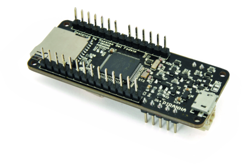
Just over a year ago we have introduced our first Arduino-like 32-bit board, called Fishino32 which was characterized by the format of the widespread Arduino UNO (but also of the Fishino UNO), although equipped with a 32-bit microcontroller capable of exceptional performances, when compared to the average prototyping board of its kind. We have also had a “little sister” ready for a long time, although we have postponed its presentation due to schedule issues and 32-bit libraries development (which turned out to be quite challenging…); But now it is time to put it under the spotlight: the board is the small “Piranha”, a name that really speaks for itself and highlights the aggressive character in terms of performances. In fact, the board uses the same microcontroller of Fishino32, which is a PIC32MX with MIPS core, 128 kB RAM and 512 kB Flash, besides a considerable 120 MHz clock, but it keeps the Arduino MKR1000 dimensions, therefore a size format just barely bigger than Arduino Nano and, in terms of length, smaller than Fishino GUPPY, although it has a respectable array of built-in peripherals. We are in fact talking about a board with a sensible computing power, however, thanks to its reduced encumbrance, it can be placed virtually anywhere.
[bctt tweet=”#Fishino Piranha: an #Arduino like board but with 32-bit architecture and very compact dimensions” username=”OpenElectronics”]
Here is an overview of the features of our Fishino Piranha:
- Processor PIC32MX470F512;
- 512 kB ROM;
- 128 kB RAM;
- 120 MHz clock;
- Native USB interface, both device and host;
- RTC on board;
- MicroSD reader;
- Onboard Wi-Fi transceiver;
- Battery-powered, USB-powered and external power (plug) from 3 to 20 V;
- Battery charger for LiPo 3,7V activated in case of external power;
- The board can be powered off via software, leaving only the standby processor on;
- Wake up by a timed external signal;
- 3,3 V internal logic;
- 5V-tolerant digital pins, so there is no risk of damaging the board with 5 V peripherals.
As you can see, the only missing thing is the audio codec, which was not included for encumbrance reasons. As for the Fishino32, the board can be programmed both through Arduino’s IDE both through our FishIDE; besides, the more advanced users have the possibilities to program the Piranha using the development systems by Microchip (MPLAB IDE and PicKit3) was also allowed to execute step-by-step debugging of the code.
Thanks to a good number of software libraries that we have written and/or adapted, which have already been well tested with the Fishino32, the board is programmed like a normal Arduino UNO, through the IDE and using the usual syntax; all you have to do is execute an easy procedure in the IDE itself to activate the development tools for the PIC microcontrollers, and there you go!
As for the additional components, we have designed a series of libraries, that are constantly being updated, which will allow taking full advantage of them.
Now, let’s take a closer look at the hardware, by analyzing the circuit diagram and the single blocks composing it. The controller stage, the Wi-Fi module and the interface for microSD cards are identical to those of Fishino32.
Power control stage
This block is probably the hardest to understand of the whole board, therefore we will provide a complete description, although we have already done it in the past for Fishino32. As you can see from the diagram, this stage is definitely more complex compared to 8-bit models and this happens for the following reasons:
- the need to work both as a host and as a USB device;
- triple power source;
- possibility to turn off the whole power stage by software;
- possibility to exclusively activate controller power during standby.
So, we need a lot of things. Let’s start with the USB power control section, which must be capable of taking power (to let the Piranha work) from the USB connector if the board is connected as device, while if it works as a host it must provide an adequate power source to a device which may be connected to the Piranha.
In order to switch, we take advantage of the pin on the USB ID line, which is connected both to the USB connector and the dedicated controller port.
The micro USB cables are designed in such a way that we have, on one end, the pin corresponding to the USB ID connected to ground (type A), while on the other and the pin is disconnected (type B); the equipment to which the type A is connected works initially as a host, and at the same time, it provides power to the other equipment, this one is connected to the type B and, which works initially as a device.
We have talked about initial roles for a good reason: in an OTG connection, the two connected devices can switch role; the specific only guarantees that the line will always be powered by the device connected to terminal A.
Let’s go back to our board and we can see that a high-value resistance (R10, 100 kohm) is connected to our USB ID line towards ground, which purpose is to not leave the line floating in case of no power, and a resistor, R5, which value is definitely lower (10 kohm) connected in common to the source of Q2 and Q3 MOSFETs. As you can see from the diagram, there is always a positive voltage (5 V minus the direct drop on the diodes) on these sources, thanks to the MOSFETs’ internal diodes; the positive voltage comes from either the USB socket or the 5 V power of the Piranha board. Therefore, we are certain that R5 is connected to +5V under any working condition. If the USB ID line is disconnected from ground (type B connection) this positive voltage, through R5, puts the N- channel Q5 MOSFET in conduction, which, in return, puts the P-channel Q4 MOSFET in conduction; at the same time, also through R5, the two Q4 and Q5 MOSFETs mentioned before are put into interdiction and, since they are connected in anti-series, they do not allow Fishino’s 5 V to flow to the USB connector.
In short, with a floating USB ID, i.e. when we insert a type B connector, the Fishino is not powering the USB connector which, on the other hand, powers the Fishino through the Q4 MOSFET. We then get to the first part of our goal, which is getting power from the USB line for Fishino through a type B connector, therefore acting as a bona fide device.
If, on the other hand, we insert a type A connector, the USB ID line is grounded, which puts Q2 and Q3 in conduction simultaneously, also through Q5, with Q4 in interdiction; the power then flows from Fishino to the USB connector and does not come back “from the back door” since Q4 is cut off.
Of course, we must notice that in the second case (type A connection) in order to provide 5 V to the USB port, Fishino must be powered in some other way, which is with the battery or the VIN plug, as we will see later.
Let’s move on down in the circuit and notice the cluster of Schottky diodes D5/D8 and D6/D7 respectively, the first two being for small currents, while the seconds are for power currents. We also see Q6 MOSFET, which is powered by the battery.
Here, the functioning is subtle; the power diodes (D6 and D7), along with Q6 MOSFET, compose an OR power gate, which goes into the VOR line of the diagram. The diodes’ functioning is quite simple: the higher voltage between VIN and VUSB is transmitted to VOR, while the other one, given the interdiction of the corresponding diode, which is inversely polarized, is isolated.
We might ask ourselves why we didn’t just insert a power diode on the battery line as we did for the other two, which could have effectively made the circuit simpler, by making a power OR gate with three diodes. This is feasible, but there is the usual problem of voltage drop on the diodes which, while basically irrelevant at high currents, leads to sensible drops in case of reduced voltage such as that from the battery: intuitively, we can say that a voltage drop of 0.5 V out of 10 V corresponds to 5%, while a drop of 0.5 V on 3.6 V is roughly equal to 14%, which is reflected on the current absorption as we’ll see later, and just where we need a higher efficiency, the battery power.
Q6 MOSFET does not have this problem, since it has no fixed voltage drop like a diode but a conduction resistance (especially low in the model we chose); on the other hand, a MOSFET can’t conduct current only when it is needed, like a diode, so we need a system to put it in conduction or interdiction as needed.
To do that, we use the two small current diodes D5 and D8; the way it works is like this: if there is no power neither on VIN nor VUSB, R18 earth Q6’s gate, which would then conduct current and allow voltage to go from the battery towards VOR. Instead, if one of the two is present (VIN or VUSB, or both) one of diodes D5 and D8 is in conduction, and positively polarizes Q6 which goes into interdiction and therefore cuts the battery off. In short, if we have an external power source coming from plug VIN or the USB connector, the battery is disconnected; if, on the other hand, there is no external power, the battery comes into play.
You can notice that the line where we find diodes D5 and D8 has a name, BATOFF, because this signal, which is at a logical level high in case of external power, is also used in another section of the circuit.

Components list:
C1, C17: 4,7 µF ceramic (0603)
C2, C9÷C14: 100 nF ceramic (0603)
C3, C15, C21, C22: 1 µF ceramic (0603)
C4: 4,7 µF 25 VL ceramic (0603)
C5: 22 µF ceramic (0603)
C6: 22 µF 25 VL ceramic (0603)
C7: 10 µF ceramic (0603)
C8: 360 pF ceramic (0603)
C16, C18÷C20: 22 pF ceramic (0603)
D1, D2, D4, D5, D8, D9: RB521S
D3, D6, D7: PMEG3020EJ
DZ1, DZ2: MM3Z3V3
Q1, Q5, Q8: 2N7002
Q2÷Q4: FDN340P
Q6, Q7: NTR4171P
R1, R15, R16: 470 ohm (0603)
R2: 3,3 kohm (0603)
R3, R4: 1 Mohm (0603)
R5, R8, R17, R18, R20÷R26, R29:
10 kohm (0603)
R6, R10: 100 kohm (0603)
R7, R9: 1 kohm (0603)
R11: 475 kohm (0603)
R12: 97,6 kohm (0603)
R13: 105 kohm (0603)
R14: 13,3 kohm (0603)
R19, R27, R28, R30: 220 kohm (0603)
U1: MCP73831
U2: SX1308
U3: LC3406
U4: PIC32MX470F512HI/MR
U5: ESP12 Modul w/ ESP8266
U6: XC6206P33
XT1: 32.768 KHz
XT2: 20 MHz
TX: blue LED (0603)
RX/PRG: orange LED (0603)
PWR: green LED (0603)
CHG: red LED (0603)
L1, L3: 6.8 µH
L2: 2.2 µH
USB: Micro USB connector
SD: Micro SD connector
LIPO: 2-way, 2.54 mm JST connector
RESET: Microswitch
Miscellaneous:
– 14-way male strip (2 pcs.)
– 5-way male strip
– 2-way male strip
– Jumper
– S1281 printed circuit (62×25 mm)
Now, let’s take a look at the component groups correlated to MOSFETs Q7 and Q8; these are used to disconnect line +3V3, which is the main line at+3,3 V, from line +3V3Core, which is only aimed to power the controller. But what is their purpose? It is simply to avoid that when the power is only destined to the controller, which is activated when everything else is off, and which purpose is to keep the internal RTC active and other minimum functionalities, flows into the circuits that we want to keep off.
Normally, when there is voltage on +3,3V, that flows through the internal diodes to Q7, and also through Q7 itself is it’s in conduction, on the power line +3V3Core of the controller; this is how it normally works. If, on the other hand, we cut off power on +3,3V and at the same time we bring the OFF line to a logical level low, we bring Q7 to interdiction through Q8 and therefore we prevent +3V3Core to power the remainder of the board. Line OFF is controlled by the controller, as we’ll see later, during scheduled switch off.
Also for encumbrance reasons, we didn’t insert a lithium button battery in the Piranha (which is by the way not very useful, since the battery power option is present).
Finally, we notice the line PWRGOOD, which is connected to a resistive partition; this provides a positive signal to one of the controller’s I/O which indicates the presence of an adequate power on the board and may be used, in fact, to manage its lack as well as standby functions.
As mentioned above, it is quite a complex management, for which a dedicated software library is available.
The last part of this section is the one regarding the linear regulator U6, which is a simple low-current regulator (max circa 100 mA) and very low consumption, aimed to provide maintains voltage to the controller through the external LiPo battery.
This section can be deactivated by cutting off the BC bridge, which is normally closed. With the bridge closed and the battery connected, we must pay attention, because without a dedicated software installed, the controller risks to stay operational, taking power from the battery and drying it up in a few hours, unless we have put everything under one of the available low consumption modes.
Since the library for managing low consumption mode (and all the power stage) is quite complex, we will describe it in detail in a future article.
Switching STAGE
This block is basically identical to that of the Fishino MEGA board described in issue 204 (April 2016), so we’re not going to describe it again; all you have to know is that it uses a high-efficiency switching converter in SEPIC mode, which is able to get an input voltage from a minimum of 3 V to a maximum of 20 V, providing the 5 V needed as output.
Battery charger stage
This stage also has already been examined dated in previous boards, therefore you can check those for the details. It is based on the omnipresent MCP73831, which is a fully integrated charge regulator for single cell LiPos. Here, the only remarkable thing is that it made of a Q1 MOSFET, an n-channel, which is used to enable or disable the charge function of the battery.
If you remember the first stage description (power control), BATOFF line is high when there is external power; in this case, Q1 MOSFET is in conduction, and earth R2, therefore, activating the charge. When there are no external voltages (battery-powered), the BATOFF line goes to level low, therefore deactivating the charge.
To complete the description, notice the two resistors R3 and R4, which comprise a voltage divider capable of providing half of the voltage differential in the LiPo battery to the microcontroller’s RB15 line, which is measured by its ADC to determine and signal the charge status.
We have used a divider because the Lipo batteries voltage, when fully charged, is over the 3.3 V allowed by the controller’s analog inputs; we must take this into consternation when we make our measurement with the ADC.
Microcontroller STAGE
Around the PIC32MX470F512 microcontroller, we can notice two quartz, a 20 MHz quartz and another 32,768 kHz one; the first provides the main clock, through an internal PLL which multiplicates it up to 120 MHz. The circuit is not really low consumption, so it should be avoided when aiming for low-energy mode; on the other hand, the 32,668 kHz quartz is exclusively used for the internal Real Time Clock (RTC) in the PIC, which is a circuit specially developed in order to have a very low absorption and therefore this can be left functioning even in standby.
If we can make with less precision for the frequency of the clock we can get rid of the quartz and use the internal RC oscillator, which however cannot bring the microcontroller to its maximum frequency (120 MHz) due to limitations of the internal PLL, therefore the internal clock would be limited to 96 MHz.
Please notice, among the many connections on the controller, the three lines we have seen before, e.g. OFF line, which allows cutting the main power, off PWRGOOD allowing to control its status and line MBAT which allows measuring the batteries voltage.
Now, let’s take a look at the reset section, which is interesting because it uses just one reset button both for resetting the micro and for other functions in combination with a dedicated loader on the microcontroller. We can see right away the three lines referring to the reset stage:
- MCLR;
- REMOTERESET;
- LONGRESET.

MCLR is the actual reset line of the microcontroller; if earth it, the micro is rebooted. We notice right away that this can be done both by pressing the reset key, which sends a short negative impulse to the MCLR line through C2 capacitor and by earthing REMOTERESET, which is related to the Wi-Fi module and therefore allows it to reset the controller.
LONGRESET line, on the other hand, is earthed as long as the reset key is held down, therefore allowing the boot loader to understand our intention. To recap:
- short pressing the reset key (for less than 2 seconds) or a negative signal on line REMOTERESET both reboot the board, as usual;
- long pressing the reset key for 2 to 4 seconds starts the bootloader (which is indicated by the orange LED blinking), therefore sending the board in sketch loading mode;
- long pressing the key for more than 4 seconds launches the firmware upgrade procedure of the Wi-Fi module, indicated by the blue LED blinking.
It is, however, possible, once we enter one of the two modes of the bootloader, to simply review the board and run the preloaded sketch by actually pressing the reset key.
As for the LED section, it is simply composed by two connected LEDs and as many controller ports, which can be used for any task (indicated on the board as RX/PRG and TX respectively); on this board, for encumbrance reasons, there isn’t the usual LED13 commonly used, for instance, for running tests with the BLINK sketch. This is however well replaced by the 2 LEDs mentioned above, which can be accessed through digital I/Os 25 and 26.
Now, let’s move to the Wi-Fi section, which is similar to that of previous Fishino because the modules still have a firmware written by us, capable of communicating at high speed using the SPI port and not the serial port.
In this board, we have eliminated the ESPCONN connector we were used to in previous Fishino, correlated to some I/Os and control pins of the module used both to program it and, in some cases, as additional I/Os.
That is because, in Fishino Piranha, we have already freed up on the I/Os used to communicate with module and the SD card, i.e. 4, 7 and 10 on UNO and Mega; besides, unlike Fishino32, we have also separated the SPI interface using the want that with dedication to the audio codec in the latter. All the ports available on the headers of Piranha are therefore free from any bond and/or interferences with internal peripherals.
Not only that, but to ports of the ICSP connector can be used as additional digital ports (we’ll talk about that in detail in the software description), therefore we preferred to take advantage of connections with the ESP module in another way. In fact, all the ESP lines (with the exception of the analog input) are now controlled by the main processor, which allows us to carry out the following operations by software, without putting a load on any I/O:
- resetting the ESP module by software;
- turning off the module by software (which previously required the use of one of Fishino’s I/O);
- uploading the firmware on the module without the need for weird connections or dedicated sketches;
- redirecting the serial output of the module on the USB serial or any other serial, both by software and hardware, which is available on Fishino.
For the remainder, nothing changes from previous ports; communication takes place through the internal SPI port which, as mentioned above, is separated from the one related to the headers in therefore externally accessible. This was possible because there is no audio codec, which is instead present on Fishino32, requiring a dedicated SPI port.
The interface towards the microSD is identical to those of previous ports; it takes advantage of the internal SPI as the Wi-Fi module, while we also use an internal I/O for selecting the board here, therefore freeing up the D4 I/O, which was needed for that purpose in 8-bitboards.
We can, therefore, use any external SPI peripheral and, even in case of some mistakes in our sketches, this will crash neither the Wi-Fi module nor the microSD board.
As a cherry on top, we have 2 additional digital ports (this time NOT 5V tolerant) available on the ICSP header, when this is not used to program the bootloader. The only big difference compared to previous boards is the lack of the level conversion stages (from 5 to 3.3 V) since the PIC is powered by 3.3 V, therefore making a direct connection possible (and faster!). The only thing we have to look out for, when executing existing sketches: the board selection pin (CS) is no longer 4 (or 10 in some versions of Arduino) but an internal pin called SDSC; all we have to do is then replace all references to I/O 4 with I/O SDCS (this is how it is written, since it can physically change from one board to another).

Header
In this section we have grouped all the connectors bringing signals outside of the board, therefore the site headers, the ICSP (In Circuit Serial Programming) connector used to program the board without passing through the bootloader (e.g. to program the bootloader itself), and on which there are two additional digitals I/Os available, and the USB connector.
As briefly mentioned when talking about the board’s features, the PIC has many 5 V tolerant I/O pins, although not all of them; this means they can accept 5 V inputs even if the controller is powered by 3.3 V, without damages. Wherever possible we have taken advantage of those pins by bringing them outside as digital I/Os; unfortunately, in some instances, this was not possible, and we had to insert an input protection using resistances and diodes.
The protection is composed of a 220-ohm resistance connected in series to the input and a diode that can discharge any excess on the 3.3 V line, therefore limiting input voltage to that value.
On the analog pins, which are not 5 V tolerant (in virtue of the analog circuitry inside the controller) there is no protection. Therefore, we must be careful not to apply voltages over 3.3 V to those, which could result in damages to the chip. In fact, the integrated has internal protection diodes, which are not, however, capable of sustaining very low currents and/or for brief periods of time, i.e. electrostatic shocks, so keep that in mind!
To finish off this section, the layout of the external connectors is basically identical to that of Arduino MKR1000, with the exception of the analog output (DAC) which is not present in the used PIC; so you can carry out almost all projects available for the MKR1000 using our Piranha, with the advantage of definitely superior performances!
Practical production
Piranha is a board completely composed of SMD components, some of which are particularly small, and it is populated on both sides. The printed circuit is a double-sided one with metallic holes and may also be autonomously produced using DIY techniques, however, it might be difficult to create the interconnection lines between the tracks of the two sides; besides, some tracks are particularly thin, which calls for a perfect incision.
The mounting requires a lot of attention and a specific equipment including of a very fine tip soldering iron and soldering led with a max diameter of 0.5 mm; flux paste on the pads may help with a soldering work and a magnifier allows to check if the solder points are well made, too big or if the components have moved.
It would be better, for some components, to make use of a hot air station and use some flux (to spread on the past, after melting a thin layer of tin on those) to ease the soldering work and prevent the soldering alloy to short-circuit adjacent pads.
Therefore we suggest to the fewer experts among you to buy the ready-made board since, in our opinion, time and material costs for a DIY production are not balanced out by the savings you may get. On our website we, however, make all the necessary files available in order to do that, as usual; the final decision is up to you. For all the mounting stages, you can follow the drawings in the next page.
STARTING UP
As mentioned at the beginning of this article, you can easily program Piranha through Arduino’s IDE, taking care of installing the package provided by us on the website fishino, containing all the additional programs needed.
The package installation, thanks to the work of the Arduino team, is definitely simple: all you have to do is open the IDE, select File that the submenu Settings and, in the line called “additional URLs for the board manager” add the following path: www.fishino.it/arduinoide/package_fishino_index.json.
As you can see from the screenshot in Fig. 1 you can insert more than one path, by clicking on the button il lets you open the window shown in Fig. 2.

Fig.1

Fig.2
Once you add the Fishino path, all you have to do is enter the ‘Instruments-Board-Board manager…’ Menu, that what lets you access the management panel of the additional boards; towards the end of it, you will find the package called fishino_pic32 by Fishino (Fig. 3).
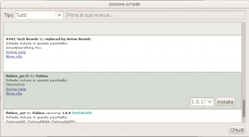
Fig. 3
Notice the Install button on the right, along with the box to select the version number. At the moment of writing, the version number 7.3.3, but the package is being continuously updated. Click on the button and the packages will be downloaded automatically, this might take several minutes; please don’t worry, because this operation must be executed only once, or anyway just in order to update it, in which case only the modified elements will be downloaded.
Once the installation is done, you will see the screenshot shown in Fig. 4.
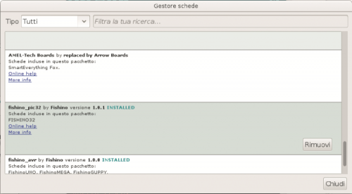
Fig. 4
Please note that now, the Install button has been replaced by the Remove button and there is a list with the available boards; do not worry if it is different from what you can see in Fig. 5, working on additional boards! Once the operation is completed, under the board selection menu you will find our Piranha, as you can see in the image.
Alternatively, you can use our FishIDE, and IDE we have developed not only for fishing awards but also for all boards compatible with Arduino’s IDE, with many additional features.
And here you go: your Piranha is almost up and running! We write “almost” because the USB drivers are still missing, and for some operating systems you will have to install those; it is not the case with Linux, in which many are included, this is not the case for OS/X either. We are talking about Microsoft Windows, which unfortunately can’t make it on its own. In fact, you will need to follow the instructions below for it.
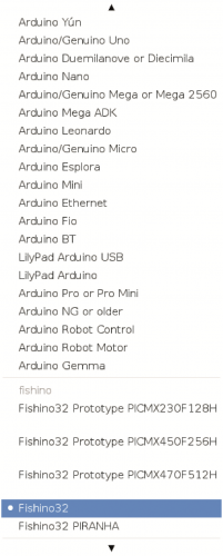
Fig. 5
USB driver installation on Windows for Fishino
The drivers are downloaded automatically together with the software package containing the descriptions of new boards we have just installed; unfortunately, they have not installed automatically in Windows OS for reasons independent of us.
For the installation, all you have to do, once you connect your Piranha to the PC, is follow the on-screen instructions, and manually select the drivers from the following path:
C:\Users\Massimo\AppData\Local\Arduino15\packages\fishino\tools\pic32-drivers-windows\1.0.0\chipKIT Drivers
In your system, the chosen path will probably be different, especially after ‘Users’ (which will be your username) and probably the version or something else too.
Once you select the file Stk500v2.inf, the driver will be installed and the IDE port will appear.
After installing (if necessary) the drivers, the system is ready to be used. You need to select the correct IDE port, which will be a COMxx on Windows or a TTYACMxx on Linux.
Executing the first sketch
We are now ready to test our board!
Here, we can find a small difference right away, which might seem an inconvenience, compared to Arduino and 8-bit Fishino boards, but which actually translates into an advantage: the board doesn’t currently have an auto-reset function that automatically puts it into sketch loading mode; so we have to push the reset button, and hold it for around 2 seconds, until the orange programming LED starts blinking, but no longer than 4 seconds, after that the Wi-Fi module firmware update mode will launch, fact indicated by the blue LED blinking.
If your timing was not right, that’s no problem… Just release the reset key and try again!
Why this choice? Simply because, since the board has native USB, this is connected to the functioning of the controller itself, as it is the case for Arduino Leonardo boards. If the controller crashes (what it takes is a crushing sketch) the USB port will no longer respond to commands, not even reset. Therefore, we currently opted for a manual system which avoids, for instance, the famous “emergency maneuver” needed in some case on Arduino boards, which is pressing the reset button “a moment” after launching the IDE programming for Arduino/Fishino.
However, it is not out of the question to insert, in a next version of the bootloader, and automatic reset system, although the aforementioned limitations still remain.
Let’s load the BLINK example from the IDE, one that makes the LED13 blink (which corresponds to the white LED on Arduino boards); as previously mentioned, there is no LED13 on the Piranha, and it must be replaced with one of the 2 Rx or Tx LEDs, corresponding to distal ports 25 or 26. We, therefore, have to edit this catch by changing all instances of “13” with, for instance, number 26, corresponding to the blue LED. We then press the reset button and hold it for around 2 seconds and, when the orange LED starts blinking, we press the button for uploading the sketch of the IDE.
After a few seconds (depending on the PC speed, the sketch complexity, the number of libraries used etc.…) The upload will be completed, which is indicated by the orange LED turns off and the blue LED blinking at the same time.
Here we go! The board has been tested and it works! And what now?
How to update the Wi-Fi module
If you have followed the articles on eight-bit Fishino boards, he would surely remember that the firmware update procedure required some on-the-fly connections between the board’s I/Os and the ESPCONN port, the preventive uploading of a “neutral” sketch, for instance, the blink, etc. Is no longer necessary on Fishino32: the board can be put into firmware update mode by simply pressing the reset key!
This is the procedure:
- Press and hold the reset key until the blue LED starts blinking; it takes 4 seconds (after the first 2, the orange LED will start blinking, in order to indicate the sketch upload mode; after another 2 seconds, the blue LED will start blinking too);
- Now, all you have to do is launch the program FishinoFlasher, and take care to have a working Internet connection on your computer, since the firmware will be downloaded from the web.
FishinoFlasher will introduce you to the screenshots shown in Fig. 6.
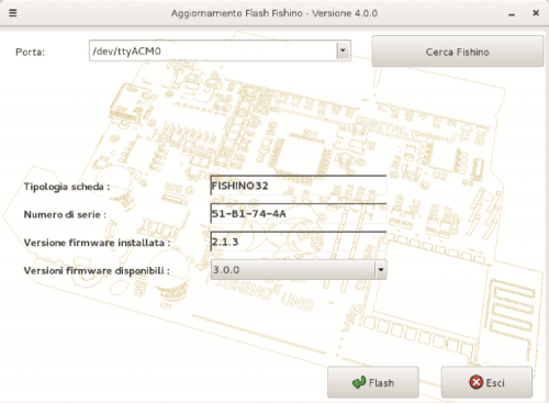
Fig. 6
In the screenshot you can notice some elements, such as the type of detected board (Fishino32), the Wi-Fi module serial number and the version of the firm were currently installed (2.1.3 in this case).
In the box below you can choose a new version to install; latest version available is suggested (3.0.0 in this case), but nothing prevents you from installing a previous version, although it is normally not recommended.
Please take care that whenever a “major” number changes in the version that means no retro-compatibility with older libraries; basically, a library which is installed and working with version
2.5.5 will also work with the firmware from versions 2.5.7 and 2.9.9 for instance, although it will not take advantage of the additional improvements (and vice versa is not true, in fact a library made for version 2.5.7 will require you a firmware version of 2.5.7 or newer!); On the other hand, that library will not work with a 3.0.0 firmware.
In short: a library developed for a firmware with a major version number X will work with all later firmware’s with the same major version number, but not with the previous ones, nor would later numbers which have a different major version number.

Fig. 7
With that said, let’s select our version and press the Flash key; after a few seconds the actual update will take place (Fig. 7) and progress will be shown in the lower horizontal bar, above the Flash and Exit buttons. At the end of the procedure, you will see a confirmation dialog for the update, as shown in Fig. 8. Now you just have to press Ok, close FishinoFlasher and press the reset on the board to exit the update mode.
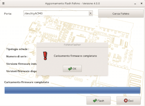
Fig. 8
Conclusion
This concludes our presentation of our new Piranha board; of course, in the next months we will propose applications based on it and we will start describing more in-depth at the various libraries and the harbor functioning of the internal components, as needed.
Among the in-depth analysis, we will dedicate one to a “new” method of programming our 32-bit boards, through a semi-interpreted language called Squirrel, offering new and interesting possibilities.
From openstore

[…] The Fishino Piranha board is available now at around $42 from the Open Electronics store. More details of the board design can be found in their announcement page. […]
[…] La tabla Fishino Piranha ahora está disponible por alrededor de $ 42 desde Tienda de electrónica abierta. Se pueden encontrar más detalles sobre el diseño de la tarjeta en el suyo. página de anuncios. […]