
Let’s complete the description of the modular development system dedicated to connectivity and IoT, deepening the discussion of the dedicated framework.
Second Episode.
In the article published in the previous issue, we introduced the Mercury System, an innovative development system, particularly suitable for IoT and connectivity-oriented applications. At that time we focused on the hardware of the system, detailing the baseboard that houses the modules and on the modules themselves; we have also introduced the MSF (Mercury System Framework), ie the development framework for the system software, whose architectural scheme is shown in Fig. 1. We have also described the steps necessary for the installation and indicated the third-party tools to install in order to develop applications with the MSF, since the latter is based on the MPLab X development environment and on the Microchip XC compiler line (in particular, it’s used for this first version of the MSF XC8).
Let’s get on to more practical matters. This will lead us to the development of our first applications with the Mercury System starting from the analysis of the installation directory of the Framework, which has already been mentioned in the previous episode.

Fig. 1
MERCURY SYSTEM FRAMEWORK
Fig. 2 shows the contents of the Framework installation folder; below we describe the contents of the individual folders created during the installation itself.
- Documentation: contains the documentation of the framework in addition to the Release Notes and all the datasheet datasheets, ie the hardware.
- MercuryFwk: contains the source code of the framework.
- MercuryProjetcs: represents the default directory for application development. It also contains some sample projects released with the framework.
- Tools: this folder contains some development tools, and in particular the host side application of the USB bootloader.
Of particular interest is the Documentation folder, which in addition to containing the various datasheets of the hardware components of the Mercury system, contains the Getting Started Guide (the corresponding file is MS_GettingStartedGuide.pdf) and the framework User Manual, containing the detailed description of all available APIs (the relative file is MS_FrameworkUserManual.pdf).
Having said that, we will now go on to explain how to create an application with our framework.

Fig. 2
CREATION OF A NEW APPLICATION
The simplest way to create a new project for the Mercury System is to take advantage of the generation script, in order to automatically configure all the paths and options necessary for the project to compile correctly. To do this, go to the MSF MercuryProjects directory and run the “CreateNewProject.bat” script, as shown in Fig. 3.

Fig. 3
Once you have launched it, the script will ask you to enter a name for the project, as shown in Fig. 4 and then create the correct MPLab X project folder structure and files needed, with the correct links to the framework ( in Fig. 5 the project creation phase is illustrated).
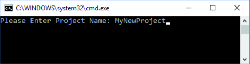

Fig. 4/5
At this point you can open MPLab X and load the newly created project, using the “Open Project …” option from the user interface toolbar of the development environment, as shown in Fig. 6.

Fig. 6
The newly created project has the default name “AppTemplate” but this name can be changed at will using the appropriate development environment option. To access this option, simply right-click on the project icon and select, from the contextual menu that opens, the “Rename” option: once the option indicated has been selected, the dialogue box will appear shown in Fig. 7, in which you will be asked to enter the new name to be given to the project. Don’t forget to also check the “Also Rename Project Folder” option, so that the folder containing the MPLab X files is also renamed correctly.

Fig. 7
At this point, you should get a screen of the Project Manager similar to the one shown in Fig. 8, in which the files related to the system configuration and the application in question are also highlighted. We will analyze these two files in detail in the following pages; for now, take them for good.
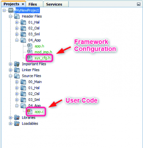
Fig. 8
By default, a new project is created with two predefined building configurations, as shown in Fig. 9. Building configurations are nothing more than, as the word itself says, different configurations with which the project can be compiled and linked. This type of configuration has an impact on memory layout, code optimization, warning level, execution speed and many other parameters that have a close correlation with the compiler and the target. In particular, the building configurations generated by default for a new project with the Mercury Framework are:
- Standalone: standalone configuration. The hexes generated with this configuration require a Micro-chip programmer to be flashed on the baseboard.
- Bootloader: configuration compatible with the bootloader. The hex generated with this configuration can be loaded into the memory of the baseboard using the USB bootloader (we will see later how to do this).

Fig. 9
As you can easily guess, this configuration acts on the memory layout, so as to allocate the application in a portion of memory subsequent to that occupied by the bootloader by default. Note that flashing a Base Board with the “Standalone” building configuration the bootloader (which by default is programmed on the BB) would be deleted. This operation can be reversed simply by reprogramming the bootloader on the Base Board (an image of the bootloader is provided as precompiled .hex in the MercuryProjects 00_Precompiled folder). To verify that the project has been correctly generated, we can try to compile it: click on one of the two buttons marked “build” or “clean and build”, as shown in Fig. 10.

Fig. 10
Once the building phase is completed, if everything is successful you will see a window similar to the one shown in Fig. 11, in which the word “BUILD SUCCESSFUL” will appear in green, to confirm that the compilation was performed without errors.
As a result of this operation you will find, in the path inside your project “.\MyNewProject.X\dist\Bootloader\production” a file with .hex extension (MyNewProject.X.production.hex) that you can use to program your baseboard, in order to prepare it for the implementation of the application in the development phase.

Fig. 11
SYSTEM CONFIGURATION FILE
The Mercury framework requires that some basic configurations be made, which must be provided in the form of user files, as they may vary from project to project.
These configurations indicate which type of modem to use, rather than the enabling or disabling of certain modules, and many other things, depending, in fact, on the desired application and the hardware it involves.
When a project is generated, the responsible script automatically creates a file called sys_cfg.h in the new project folder; this file contains all the static configurations of the specific project and it is the user’s responsibility to modify it according to his needs.
In TABLE 1 you can see a list of the most important configurations of a project realized with the Mercury System Framework.
Table1

APP
When the generation script is launched, in addition to the configuration file, the latter also creates a pair of files called “app.c” and app.h that can be used as a template for the development of the main application.
The “app.h” file contains a single relevant configuration, ie the macro:
#define MY_APP_TASK_PERIOD_MS ((UINT16) (50))
which determines the execution period of the application task.
By default, the latter is 50 milliseconds, but the value can be changed by the user within certain limits.
The app.c file instead contains the actual definition of the task, which is composed of a switch..case structure with two houses:
- InitializationState
- RunningState
These two houses represent the states in which the application task can be found and, as can be easily seen from the name, the first represents the initialization status (executed once at startup), while the second represents the running status ( executed periodically at the periodicity of MY_APP_TASK_PERIOD_MS).
Wanting to make a parallel with the Arduino world, these two states of the application task represent the setup and loop routines that represent the bases of a sketch created with the Arduino IDE.
Fig.12 illustrates graphically the above.

Fig. 12
Therefore, to realize our application we will not have to do anything but realize our application code and make calls to our initialization functions and to the periodic functions within the MyApp_Task task. Being based on a cooperative RTOS (Real-Time Operating System), the Mercury System goes very well with Mac-china-style implementations in the Finite States; not by chance, this is the methodology that we will use in the practical projects that we will propose to you in future articles.
It is important to consider that calls to blocking cycles, such as while or for infinite, cannot be made, as these cycles would block the execution of the “main functions” of the Framework. We will cover this aspect in more detail when we make the first practical examples.
USE OF THE BOOTLOADER
As we saw earlier, the Mercury System Base Boards can be programmed using a bootloader, and we have also seen which is the building configuration that allows generating a hex file compatible with the Mercury bootloader. What we still need to describe is the actual bootloader programming process.
Before flashing an application on a Base Board using the bootloader, the latter must be correctly activated.
The sequence to activate the bootloader is very simple:
- you need to connect the BB (off, ie with the main switch in the “OFF” position) to the PC using a microUSB cable;
- then press and hold the SW1 button (boot switch);
- finally, power can be supplied to the Base Board, moving the main switch to the “ON” position.
In essence, the bootloader is activated if, at the start of the board, the digital line connected to the SW1 button is at a low logic level.
Activation of the bootloader is confirmed by the LD1 LED, which will flash at high frequency. At this point, it is possible to start the host application of the bootloader (from the shortcut “MercuryBoot”, present on the desktop or in the start menu). If the Base Board is the host application communicating correctly, you should see a screen like that shown in Fig. 13 appear on the screen, indicating that the device is in the “Attached” state.

Fig. 13
At this point it is possible to select the “Import Firmware Image” option from the file menu or from the shortcut icon in the form of a folder; the screen that allows you to choose the hex file to load will appear (remember to use the file generated with the build configuration “Bootloader”).
Once the hex file is correctly loaded, it is possible to flash the Base Board using the “Erase / Program / Verify device” option (from the Program menu or via the shortcut button with the symbol of the file and the integrated joined by an arrow).
If everything is successful you will see a screen like the one shown in Fig. 14, which indicates that the bootloading process has been successfully completed. At this point you can reset the board (from the main switch or using the “Reset Device” option of the MercuryBoot application), to allow the newly loaded application to start running.
Of course it is also possible to program the BB using a normal programmer for Microchip devices, and in this case, it is also possible to use advanced debugging features (depending on the device used). In the latter case, however, care must be taken to use the standalone configuration, or alternatively load the hex image of the bootloader as “Loadable” of the MPLab X project. The BB exposes the programming pins (MCLR, PGD and PGC) and a connector compatible with the Microchip standard is always shown on the expansion boards (it is suggested to refer to the Base Board and Expansion Board datasheets for more details).

Fig. 14
FIRST PRACTICAL EXAMPLE: HELLO WORLD
Now that we have completed a first overview of the development framework (there would be much more to say, but here we limit ourselves to a purely “user” description), let’s move on to the first, simple practical examples. As a first example, we realize the classic Hello World program, which makes an LED flash at a predetermined frequency. The Base Board 110 will be the hardware support for this first example
So let’s create a new project called “HelloWorld” following the instructions in the previous section and open it with MPLab X.
In Fig. 15 we show the screen of the project manager of our first example.
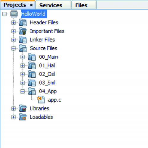
Fig. 15
What we propose to do is to make the LD1 LED flash at a frequency of 1Hz (so 1 second on and a second off).
To implement this simple application, the framework comes to our aid, and in particular the “SSL LED module, which already has pre-packaged LED management functions, and in particular the two functions “Led_SetLedBlinkTime” and “Led_SetLedStatus”, of which we report the descriptive charts (Fig. 16 and Fig. 17), extracted from the User Manual.

Fig. 16
As can easily be guessed from the descriptive tables, through the first function we set the flashing times, while with the second we put the LED we wish to flash in blinking status (LED_STS_BLINK). Then the framework will take care of making the LED blink for us. We will then have to call the function “Led_SetLedBlinkTime” with arguments LED_1 (Macro referencing the LED LD1), and 1,000 for the two flash times (since the times in this API are expressed in ms):
Led_SetLedBlinkTime (LED_1,1000,1000);
and then call the function “Led_SetLedStatus” with arguments LED_1 and LED_STS_BLINK (enumerative which indicates that the referenced LED must be set in blink status:
Led_SetLedStatus (LED_1, LED_STS_BLINK);

Fig. 17
So the code of our application is reduced to the one shown in Listing 1.
Listing1
void MyApp_Task (UINT8 Options)
{
switch (SystemState)
{
/* System Initialization Phase */
case InitializationState:
/* Make app init. if necesary */
/* Set LED blink timing */
Led_SetLedBlinkTime(LED_1,1000,1000);
/* Set LED_1 in blink mode */
Led_SetLedStatus(LED_1,LED_STS_BLINK);
break;
/* System Normal operation Phase */
case RunningState:
/* App periodic calls */
break;
/* Default */
default:
break;
}
}
To test the newly written application we can compile and program via the bootloader, as described in the previous section.
SECOND PRACTICAL EXAMPLE: BT RELAY
After this first simple example let’s move on to something slightly more complex and more oriented to connectivity: a BT remote control that allows us to activate and deactivate a relay. For this second example, we will need a more complete set of boards, as we will also need a board with a relay and a BT modem. The necessary boards are, therefore:
- A BB110,
- An SB110 (relay board),
- One MB310 (BT modem).
For the interconnection, it is possible to connect the three bunk boards, but in the realization of this example, we used an EB110 (dual expansion board), as it appears in the hardware illustrated in Fig. 18. What we propose to do in this case it is to activate a relay on receipt of the string “R1: 1” and deactivate it when “R1: 0” is received, on the BT channel. The choice of strings is totally arbitrary and can be changed at will by the user. We proceed by generating a new project, as seen above and opening it with MPLab X. Also, in this case, the functionalities of the framework can be very useful, as there are already APIs for the management of BT and I²C communication.

Fig. 18
The APIs we will use in this case is the following:
- I2cSlv_SendI2cMsg (sending a data buffer on the I²C bus);
- MdmBt_ReceiveBtMsg (a receipt of a string from the BT channel).
The relative descriptive tables are shown for convenience in (Fig. 19 and Fig. 20):


Fig. 19 and Fig. 20
To understand, instead, what data to send on the I²C bus to activate the SB110 relays, we need to consult the datasheet of the latter board, which shows the command set supported by this slave board, which for convenience is reported in Fig. 21:
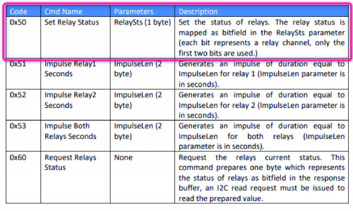
Fig. 21
The command that interests us is the 0x50, that is Set Relay Status. For example, if you want to activate or deactivate relay 1, you will have to send the following commands to the I²C bus:
- relay activation: 0x50 0x01
- relay deactivation: 0x50 0x00
This approach is valid in general; when you want to use a certain one
Slave Board for the development of an application, it is worth checking immediately its datasheet and in particular the list of supported commands. This set of commands is also periodically updated by the Mercury system developers.
Instead, as regards addressing on the bus, since we have only one slave we can use the broadcast address 0x00 without having to worry about setting the address on the SB110 as all the slaves respond to this particular address. Alternatively, we can use a different address, but we will have to take care of setting it using the appropriate dip-board of the slave board. Using the APIs and information obtained from the datasheet we have created the very simple function shown in Listing 2, which must be invoked in the running status of the application task.
Listing2
void ManageBtCmd (void)
{
UINT8 BtRxBuffer[10];
UINT8 RxDataLen;
/* If a message is received from BT modem */
if ((MdmBt_ReceiveBtMsg(BtRxBuffer,&RxDataLen)) == BtMsg_Received)
{
/* Check data */
if (strstr(BtRxBuffer,(void*)"R1:1"))
{
I2cTxBuffer[0] = 0x50;
I2cTxBuffer[1] = 0x01;
I2cSlv_SendI2cMsg(I2cTxBuffer,0x00,2);
}
else if (strstr(BtRxBuffer,(void*)"R1:0"))
{
I2cTxBuffer[0] = 0x50;
I2cTxBuffer[1] = 0x00;
I2cSlv_SendI2cMsg(I2cTxBuffer,0x00,2);
}
else
{
/* Do nothing */
}
}
}
As you can see from the listing, the MdmBt_ReceiveBtMsg function is used in an if… else if … else selection structure to understand if a message has been received from the BT channel (and eventually copy the bytes received into the BtRxBuffer receive buffer, together with their number in the variable RxDataLen). In the event that a message has actually been received, it is searched, by means of the strstr function, of the strings library of C, if the string “R1: 1” or “R1: 0” is present inside the reception buffer BT. If the string “R1: 1” is found the relay is activated by sending on the bus 0x50 0x01, while if the string “R1: 0” is found, the relay is deactivated sending 0x50 0x00.
As you can see no cycles of any kind have been used, but the property of the application task to be periodic is exploited, and therefore to provide a cyclic execution itself (in the specific periodic, with a periodicity equal to MY_APP_TASK_PERIOD_MS).
Having to use the Bluetooth modem in this example we will have to take care of correctly configuring the framework, setting the macro “MODEM_USED” of the file sys_cfg.h to the value “BT_MDM”, to enable the relative stack. Also remember, as indicated above, to invoke the “ManageBtCmd” function in the “RunningState” state of the application task, as shown in Fig. 22.

Fig. 22
To test our new application we can use any Bluetooth terminal (PC or smartphone or tablet), or the special Android application supplied with this example, a screen of which is shown in Fig. 23.
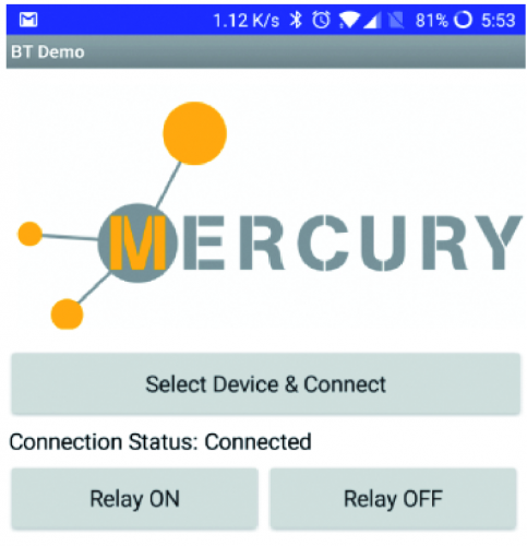
Fig. 23
Using the Android application is very simple: first we pair the composed system with our Mercury boards to our mobile phone, using the BT pairing utility (the default pin of the BT modem is “1234”), then we launch the application and, using the “Select Device & Connect” button, connect to the board. If the operation succeeds, we will be able to check the status of the relay using the two “Relay ON” and “Relay OFF” buttons that we find on the app screen.
CONCLUSIONS
In this second and final instalment, we completed our overview of the Mercury System Framework, illustrating how to create new applications with this development tool and also providing the first simple practical examples. In the next few articles, we’ll present new and more complex applications, which exploit the potential of the system to implement connectivity, home automation, IoT and much more.
From openstore
