
Modular development system that simplifies connectivity and IoT applications: based on boards that can be combined as LEGO bricks, on a complete software framework.
Allows scalability and modularity.
The Internet of Things (or IoT, whether you prefer), ie the capacity of certain objects, equipped with sensors, actuators and wireless interfaces, to connect to the Internet and exchange data through it, is proving to be one of the most interesting technological trends in recent years. The first examples of widespread commercial applications are beginning to appear in our homes, especially lately with the spread of Amazon and Google voice assistants. Further examples will be found in the immediate future, with the introduction of additional categories of connected objects.
It is, therefore, necessary for developers and makers to begin to be interested in the subject, so as to be ready to develop their own applications or to extend existing ones to the IoT world. However, developing an IoT application (or at least the embedded part of it) can be a far from easy task: first of all you need to get a hardware (or a system of electronic boards) suitable for the purpose; it should be noted though that in the IoT context the hardware can be very different depending on the application, on the actuator or the sensor required for the connected device.
In addition to this basic problem, our hardware will have to be equipped with specific network connectivity that we want to use for our application. In this case too, in IoT or connectivity applications, in general, the situation can vary from application to application, depending on the specific type of network: we can have WiFi, GSM / GPRS, Zigbee solutions, up to the most recent technologies like LoRa and Sigfox.
Of course, we will also need an SW development environment that allows us to write and compile the embedded code of our device. It will also be necessary to meet the power requirements of our object, which in the case of IoT applications can also be quite complex, as in the case of battery powered devices or equipped with energy harvesting solutions.
The last requirement, but not least: at least for the prototyping phases and for the most “maker” applications, our system should allow a robust and as simple as possible mechanical assembly, minimizing flying wires, welding and in general poorly cleaned connections. Basically, finding a development system on the market that encompasses all these characteristics is not an easy task.
The Mercury System responds to this growing need.
What is about?
Mercury System is essentially a modular development system, hardware/software, specifically designed to allow the development of IoT, and in general connectivity-oriented applications. The system is composed of a heterogeneous set of hardware components on dedicated boards, which belong to the families described below.
- Base Board (BB): it is the “brain” of the whole system and contains the main logic unit (a microcontroller) in addition to the various communication buses and interfaces to connect to the rest of the system. In addition, the BB contains a simple power supply system with an integrated LiPo battery recharging system, able to meet the power requirements of the simplest systems (tendentially up to 1A). It is also equipped with a USB bootloader, so it can be easily reprogrammed. This board can exist in different variants, depending on the microcontroller used.
- Modem Board (MB): the board that implements connectivity to the network (or to an external device, such as a smartphone). It can exist in different variants, depending on the network interface (WiFi, GSM / GPRS, Blue-tooth, ZigBee, LoRa, etc.). It is interfaced with the BB through a dedicated interface.
- Slave Board (SB): all system devices belong to this family. These are essentially the various sensors and actuators that can be used for developing applications with the Mercury System. Typical examples are boards with relays, temperature sensors, servo controllers, ultrasonic sensors, etc. The SBs are equipped with a local microcontroller, which implements a set of commands for managing the sensor or the specific actuator, in order to simplify the management and allow greater scalability. The interface to the BB via an I²C (multidrop) or UART (peer-to-peer) connection, as appropriate.
- Power Board (PB): the board that allows satisfying the power requirements of the system, when necessary. In this case, too, the boards can be different, depending on the particular power or power requirement (battery, solar energy harvesting, piezo energy harvesting, etc.).
- Expansion Board (EB): these boards allow you to connect the system on the same plane, offering greater expansion than the classic “stackable” configuration, which is always possible. In some cases, these boards may also contain peripherals, such as LCD displays, battery sockets, prototyping areas and so on.
- Brain-Less Board (BL): the controller’s slave boards belong to this family, ie without intelligence on board. Generally, these boards contain very simple sensors or actuators, which can be interfaced directly to the BB’s GPIO, without the need for a bus connection. They are designed for cost-sensitive applications, generally being less expensive than the SB equivalent.
Fig. 1 shows an example (purely theoretical) of connection of the various HW components of the Mercury System, in which all the families of boards are used. Fig. 2 shows, instead, some examples of BB, SB, MB and EB.
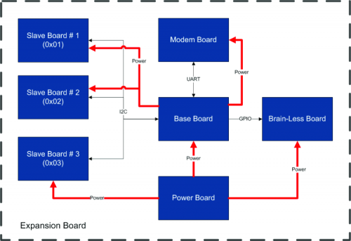
Fig. 1
Slave Boards and Modem Boards are supplied pre-programmed with a firmware that implements a set of dedicated commands that allows a higher level management of the board, while for the programming of the BBs a complete SW Framework is provided which implements all the services. low level (operating system, device driver, system services, etc.), so as to leave only the development of the application logic to the user.
We will now analyze in detail the various families of boards that make up the system.
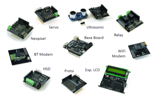
Fig. 2
The base board (BB)
The Base Board is the main component of an application developed with the Mercury System, as it contains the logic of the application itself and provides all the interfaces necessary for managing the rest of the system. The main task of the BB is to act as the Master of the system, interfacing Modems and Slave Boards by running the user application.
In addition to this, as previously indicated, the BB contains a simple power supply circuit with a LiPo battery (single cell), allowing to satisfy the power requirements of the simplest systems, even in the case of which requires battery power.
Fig. 3 shows an example of Base Board, the BB110. In the rest of the article when we talk about BB generically we will refer to this particular model; however, although this is actually the only basic board model on the market, others may be developed in the future.
The BB contains two main connectors, which guarantee to interface with the rest of the Mercury System:
- the Mercury Standard connector;
- the Mercury Modem connector.
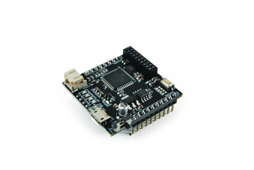
Fig. 3
Using these two connectors the BB can interface with Slave Board, Expansion Board, Brain-Less and Power Board (Mercury Standard Connector) and with the Modem Board (Mercury Modem Connector).
The BB is equipped with the following main components (Fig. 4):
- a PIC18F46J50 microcontroller, equipped with a USB Bootloader;
- a power supply circuit with a single LiPo cell charging unit;
- a Full-speed USB interface, with a micro USB connector;
- an I2C EEPROM memory;
- an internal RTCC, powered by a 32 kHz low-power oscillator;
- three LEDs and one button;
- a Standard Mercury connector (with I²C, UART, Ext. Interrupt pins and up to 11 GPIO);
- a Mercury Modem connector;
- a main slide power switch.
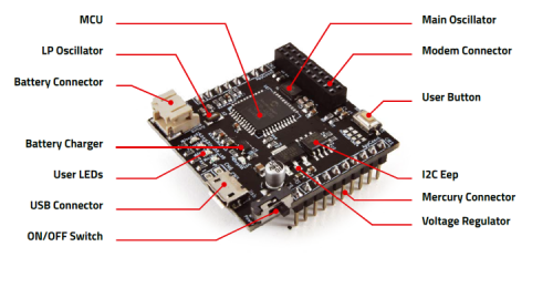
Fig. 4
Fig. 5 shows the block diagram of BB110, of which, in the following pages, we report the wiring diagram and the component assembly plan. As you can see, the heart of the entire system is a PIC18F46J50 microcontroller, produced by Microchip Technology. The micro interfaces to the two Mercury connectors, through which it can manage, via the buses and digital lines present, the other boards that make up the system (Modem Board, Slave Board, etc.).
In addition, the BB110 is equipped with a USB slave connection, which acts both as an entry point for the bootloader that guarantees the possibility of updating the FW, as well as the main power source for the system (if you do not want to use the USB to power the system you can alternatively use the CN6 connector). The board can also be battery powered, via the CN3 connector (two-terminal JST, a very common standard for lithium batteries). A connected battery is also recharged from the main power source via the integrated U3, a lithium battery charger model MCP73831, always produced by Microchip. Downstream of the charging circuit we find the U4 regulator, model MCP1825S, which supplies a regulated voltage of 3.3V to the rest of the components of the board. Moreover, since the PIC18F46J50 is not provided with an internal EEPROM, an external I²C (U2) memory has been added, in particular, a 16kbit 24LC16, in order to also satisfy any non-volatile data storage requirements. Finally the board is equipped with some contour elements, such as the LEDs LD1, LD2, LD3 (available to the user), the SW1 button (which in addition to being used to get the system into boot mode, can also be used by the ‘user) and finally the dividers referring to the analogue inputs AN0 and AN1, which allow to detect the state of the main power source and the battery voltage.

Fig. 5
The modem board (MB)
As we have seen before, the board that guarantees the Mercury System the connectivity features, indispensable for the development of applications
IoT cations is the Modem Board.
The MBs are interfaced to the BB through a dedicated UART connection and other control lines (which may vary from modem to modem). All these communication and control lines are incorporated into the Mercury Modem Connector. The support of emerging connectivity technologies can, therefore, be easily supported with the introduction of new Modem Boards, therefore a high level of scalability is intrinsically guaranteed. Fig. 6 shows some examples of Modem Board.
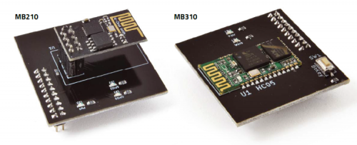
Fig. 6
The slave board (SB)
To enable the development of the most diverse applications, the Mercury system provides a vast set of Slaves boards, each of which contains a specific sensor or actuator (relay, temperature, servo, ultrasound, infrared, HSD, accelerometer, PIR, etc.). ), managed by a local microcontroller that interfaces to the BB via a bus.
The layout of the Slave Boards is standardized, so as to simplify the interfacing with the Base Board and guarantee a high level of modularity and scalability. Each SB is equipped with an I2C connection and a 4-position dip-switch, with which it is possible to dynamically set the slave address. The addresses from 0x01 to 0x0F are available for the slaves, while the address 0x00 is reserved for broadcast communications (general call in I2C). In this way up to 15 devices can be connected on the bus, using dynamic addressing. Furthermore, on the Standard Mercury connector, there are also two digital lines in open-collector configuration, connected to two external interrupt inputs of the Base Board, so that the slaves who are equipped with it can use this connection to carry out requests for attention or to notify particular situations in a completely asynchronous way. Finally, a UART line is also available for slaves that require greater bandwidth or peer-to-peer communication. Fig. 7 shows an example of a connection with four Slave Boards.
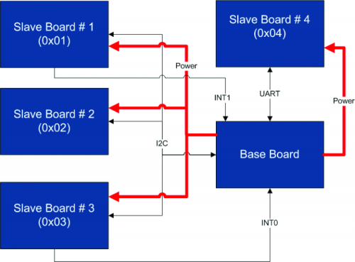
Fig. 7
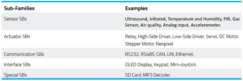
Slave boards can be divided into different sub-families, depending on the specific peripheral device mounted:
- Sensor SB;
- Actuator SB;
- Communication SB;
- Interface SB,
- Special SB.
In table 1 some examples are proposed for each of the subfamilies.
In Fig. 8, Fig. 9 and Fig. 10 are shown some examples of Slave Boards.
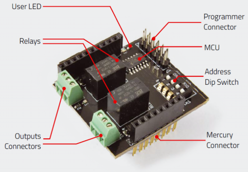
Fig. 8
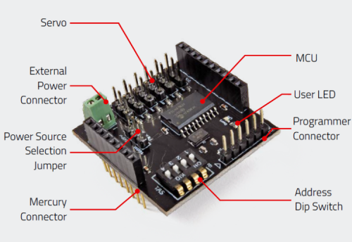
Fig. 9
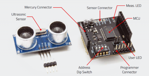
Fig. 10
The expansion board (EB)
Given that an application developed with Mercury System can be composed of several tabs, an alternative way of connecting was conceived, replacing the classic “stackable” configuration (Arduino-like), which, while still possible, is certainly inconvenient if they have to be connected more than 2-3 boards. This alternative configuration is allowed by the Expansion Boards, which are nothing more than boards containing different Standard Mercury Connector sockets, interconnected with each other. This allows you to connect the boards on the same plane, rather than in the “stackable” configuration, or even make mixed connections with both types. In addition, these boards have expansion connectors that allow different EBs to be interconnected and can have additional features, such as integrated LCD displays, battery sockets, prototyping areas, etc.
Fig. 11 and Fig. 12 shows two examples of Expansion Board: the EB110 (dual-slot Expansion Board) and the EB210 (Expansion Board with LCD display).
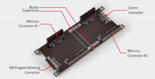
Fig. 11
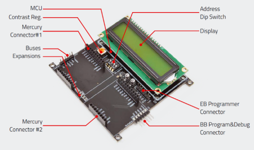
Fig. 12
The power boards (PB)
Although the BBs are equipped with a simple power supply circuit, this may not be sufficient to meet many of the requirements
of power that can be required by many applications. For this reason, a further family of boards was introduced: the Power Boards (PB).
These boards allow the system to have the same scalability for the power and power requirements as the system has for Slave and Modem Board.
Some examples of Slave Boards are:
- Power Board for currents up to 5A,
- Power Board for currents up to 10A,
- Power Board with Solar Harvesting,
- Power Board with Harvesting Piezo.
The brain-less boards (BL)
Brain-Less is the simplest form of the system’s Slave Board. Essentially it is a Slave Board without a local microcontroller (Brain-Less). These boards are designed for the simplest and most cost-sensitive applications, where few and simple actuators or sensors are used.
Some examples of Brain-Less are:
- Brain-Less Relé,
- Brain-Less Proto,
- Brain-Less Digital Input.
The mercury system framework
As already mentioned previously, the Mercury system is not only an HW development system but also integrates a development framework to simplify the development on the SW side.
This framework is called Mercury System Framework or, in short, MSF.
The Mercury System Framework is a complete SW framework specifically designed to simplify application development with the Mercury System.
The MSF provides the user with a complete set of features to easily interface the SB and MB, as well as some basic infrastructure and system services. Fig. 13 shows the SW architecture of the MSF.
The Framework consists of the following layers:
- HAL (Hardware Abstraction Layer): this is the hardware abstraction layer and contains all the drivers for the management of basic micro peripherals, such as I²C, UART, Timer, Interrupt, GPIO, etc. Its task is to present to the upper levels simplified management of these peripherals.
-
SML (System Management Layer): this is the management layer of communication and system services. At this level, the API for managing the modems, the communication with the slave boards (I²C and UART) and the USB communication are implemented. Furthermore, some system service managers such as RTCC, Power Management, terminal, etc. are implemented.
This level is divided into two main components:
- PML: Peripheral Management Layer,
- SSL: System Services Layer.
- OSL (Operative System Layer): this level implements a lightweight RTOS that provides some basic infrastructure services such as scheduling tables for tasks, events, SW Timer, alarm and so on.

Fig. 13
Using the MSF it is possible to develop applications in a very simplified way, being able to take advantage of all the APIs made available by the framework for managing communication, system services, etc. The user only needs to worry about the IoT application to be developed.
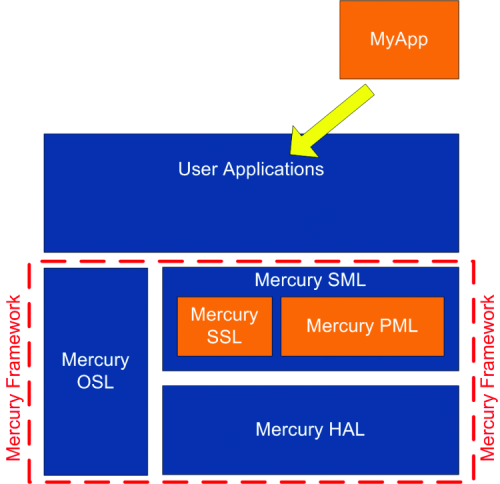
Fig. 14
Installing the framework
The MSF can be downloaded from the link http://bit.ly/MercurySF or from the BB110 web page. In the Documentation and useful links section of this page click on Framework Mercury and start the download.
Once the package has been downloaded and the installation has started, you will see the welcome screen, in which you will click on the Next button to continue, thus accessing the next dialogue box, which is the Wizard’s (Fig. 15). In this you will have the possibility to select the installation path; in this regard consider that, although it is possible to choose any path, we suggest to keep the default one. Once you have made your choice click again on the Next button to proceed.

Fig. 15
On the next screen (Fig. 16) you can choose to create an icon on the desktop and on the “Start” menu. Confirm both choices if you wish and press “Next” again to start the actual installation of the framework.
If all goes well, after a few moments you will see the screen that informs you of the completion of the installation operations.
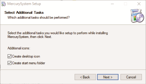
Fig. 16
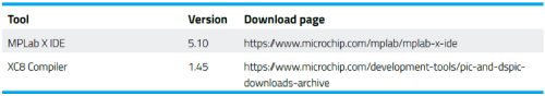
Please note that in order to use the Mercury Framework you need some additional development tools, which you will need to download and install, as the MSF relies on the Microchip development toolchain, and in particular on the MPLab X IDE and XC family compilers. The current version of the MSF makes use of the tools (and related versions) shown in Table 2.
For the installation of the tools mentioned above, we refer you to the respective sections on the Microchip website. We only emphasize that it is important to respect the versions indicated, as although the framework can work with more or less recent versions, it has not been adequately tested, except with the indicated versions.
Table 2
Conclusions
In this first episode, we introduced the Mercury System and illustrated its various HW / SW components, also analyzing the SW development framework. In the next installment, we will go into detail on the development of applications with this innovative system and we will see the first, simple examples.
Components List:
R1, R2, R3, R8, R12: 330 ohm (0603)
R4, R6, R18, R19: 2.2 kohm (0603)
R5, R7, R17, R20: 4.7 kohm (0603)
R13, R14, R15, R16: 47 kohm (0603)
R11: 2 kohm (0603)
R21, R22, R23, R24: 0 ohm (0603)
C1, C7: 10 nF ceramic (0603)
C2: 10 µF ceramic (0805)
C3, C6: 22 pF ceramic (0603)
C4, C5, C11, C13, C14: 100 nF ceramic (0603)
C8: 4.7 µF ceramic (0603)
C9: 10 µF 16 VL electrolytic (Ø 4mm)
C10: 4.7 µF 6.3 VL ceramic (0805)
C12: 1 µF ceramic (0603)
C15, C16: 33 pF ceramic (0603)
LD1, LD2, LD3: LED yellow (0603)
LD4: green LED (0603)
LD5: red LED (0603)
SW1: Microswitch
SW2: Slide switch
U1: PIC18LF46J50T-I / PT
U2: 24LC16BT-I / SN
U3: MCP73831T-2ACI / OT
U4: MCP1825S-3302E / DB
X1: Quartz 8 MHz
X2: Quartz 32.768kHz
From openstore

[…] Mercury System: IoT & Connectivity Made SimplePosted 3 weeks ago […]