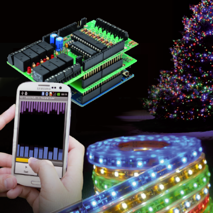

This post is about a light animation game that can light up your Christmas. There’s Bluetooth, Android and audio files: a perfect festive mashup. A spectrum analyzer will help us color the winter festivities.
Every year at Christmas we always want to try something new for lighting up our decorations: everyone wants to impression friends and families coming to visit with her creativity! So, this year we propose you an interesting idea: a system that manages the lighting according to your favorite song.
For the audio section we will use the audio capabilities of your Android Smartphone: it can reproduce and analyze audio files in real-time (supported formats are MP3 and WAV). The hardware part will be that of an Arduino board plus a shield suited with expansions. The communication between the two units will be done via bluetooth.
The operation of the system as a whole is quite simple: an Android app will leave you the ability to pick and play sound files. The app analyzes the corresponding spectrum in realtime and, depending on the level detected in some frequency bands, activates or deactivates the lights that make up our lighting system.
The audible spectrum is divided into eight bands, each band is evaluated in amplitude and compared with manually set threshold. As said, the hardware consists of an Arduino Uno board plus two shields: the I²C I/O Expander an a Bluetooth RN-42 shield.
The first shield is used to manage lights ignition (in particular, the system is equipped with 8 relay outputs connected to the different rows – can be traditional lights or LEDs ). The second shield will be used to run the bluetooth link between the smartphone and the Arduino, so tha the user can control the lights via the smartphone.
Being the Expander shield equipped with 8 relay output, it is easy to understand why you chose to split the audio spectrum 8 frequency bands, as for the Bluetooth: all Android smartphones have this wireless connection, after all it allows a decent baud rate.

In summary: you start the app, you select which device to connect and choose the audio file to be played. At this point, everything is handled automatically by the software: the sound signal is analyzed to identify which outputs to turn on or off, and these results are sent continuously (at 10 milliseconds intervals) to the Arduino board, that activates or deactivates the relay outputs.
Finally, in case the app is no more running or the bluetooth link is down the firmware runs the outputs according to random sequences.
The Wiring Diagram of the I²C I/O Expander Shield
Let’s begin by analyzing the I²C I/O Expander shield: all is based on the component U1: the I/O Expander MCP23017 manufactured by Microchip.

As described in the datasheet, this has a total of 16 GPIO pins (divided into two ports called A and B) individually configurable as input or output. In our scheme, we decided to set all the 8 pins of port A as outputs and 8 pins of port B as inputs. The outputs end on the U2 (ULN2803), tha’s especially designed as a relay driver.
Inputs instead (port B) are connected to the appropriate circuit sections which carry the digital inputs. Note that in the application described in this article these will not be used but, for the sake of clarity, we also look at them since will be useful in future projects. Each input has a protection diode, a resistor pull-up and a LED. When the input is logically low (to ground) the corresponding LED is lit up while the I/O Expander indicates that the input is “0”; vice versa when the input is high, the relative LED is off and the I/O Expander indicates that the input is “1”.
MCP23017 management goes through the I²C Bus and specific registers. The I²C bus is made from two pins, 13 and 12 (SDA for data, and SCL for clock) that are connected to the respective pins on the Arduino board.
The MCP23017 provides the ability to generate an interrupt when a variation of at least one input pin: in our case we don’t use this feature, but it might be useful to handle inputs from Arduino in interrupt mode and not with polling (which provides more speed without burdening the I²C bus). Of course to take advantage of this feature you must write the appropriate firmware.
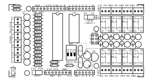

Furthermore, in the shield we provided you with the possibility to bring (via a jumper) the MCP23017 interrupt pin (INTB, pin 19) as an input on two different pins on the Arduino (D2 or D4) to fit as much as possible with the actual use.
I²C-Bus address of the MCP23017 is selected via dip-switch SW1; three dip are present therefore it is possible to connect up to eight different shields without interfering with each other.
Finally, it a power supply section is present composed by the U3 regulator (L78L05) which transforms the input voltage Vin to the 5 volts needed to operate the entire circuit. Also note that through the JP5V bridge you can choose to bypass the regulator and use the 5V supplied directly by the Arduino board.
The Arduino I²C I/O Expander Shield Library
We developed a brand new Arduino library for the project: it provides all the routines needed for the detection of the shields connected and the management of the I/Os.
The communication with the MCP23017 is based on the I²C-Bus, so the library uses Arduino’s “Wire.h”. A function “begin (int i2cAddress)” initializes the shield identified via I²C address, a “init()” function helps program the internal registers of the chip according to our needs and finally “pinMode (int pin, int mode)” indicates whether the individual pins of I / O is input or output.
Besides the initialization functions, key functions are the “digitalRead (int pin) “,” digitalWrite (int pin, int val) “,” digitalWordRead() “and” digitalWordWrite (word w) “, respectively, allowing you to read the state of a single input pin, write a single output pin, read the status of all the input pin (8 in our case) and finally write the state of all output pin (still 8).
As anticipated above, the management of the input can be via done interrupt; therefore a special function is present: “pinDisableINT (int pin)” allows you to configure the pin as a single interrupt generator (in certain applications it may be useful to have the option not to set all the input pins as interrupt generators but do it selectively.)
The Wiring Diagram of the Bluetooth RN-42 shield
The fundamental component of the shield is definitely the RN-42 bluetooth module: the module, in addition to having a chip for the integrated management of the bluetooth stack, sport several communication ports and some input / output pins.
For diagram see our previous post.
The Arduino Firmware
Having defined the software libraries for the management of I/O Expander shield and the Bluetooth module, the realization of the Arduino software is easy and fast.
Arduino’s CPU is responsible for managing both the I2C communication with the input/output (logic read/write) and with the RN-42 (managing requests for new connections or disconnections and sending data).
As for the hardware resources: in addition to the I²C bus and the serial port required by the shield, only pin 13 is used as an output to handle the signaling LED on the Arduino board. 36 bytes of EEPROM are used to store the name and associated bluetooth pin code.
In the “setup()” feature the digital pin is configured, once the EEPROM is initialized, the I²C bus is launched and finally checks to which of the 8 possible shields the I/O Expander is connected. This is done with the I²C bus and, in particular thanks to the ACK that the slaves give in respond to different commands. If the shield is connected the input and output directions of the MCP23017 are set according to the wiring diagram.
Subsequently, through the appropriate serial commands the RN-42 module is configured: in particular, it is configured as a slave (“SM,0″) and the default name and PIN code (” 5555 “) are set.
Later we enter in the main loop of execution in which the bluetooth communication is run: it tests for the presence of new byte in the receive buffer of the serial, and if so these are analyzed. The condition for the request of new connections, of disconnections or bytes are processed according to the rules of the communication protocol.
In particular, there are only write commands: writing the state of the relay outputs and programming the bluetooth configuration (name and pin code.)
As mentioned above, in order to obtain an almost real-time working mode, the sending the status of the relay outputs must take place at a fairly strong (about 10 msec) rate, and this led us to define a communication protocol that is as simple as possible and that yields the minimum time of transmission and data analysis. In particular we defined simple packages with a maximum of 3 bytes with one byte of control information, and the rest of made of the real data.
Also the calculation of the bluetooth disconnect time-out we used a minimum delay of just 5 msec but repeated more frequently.
/****************************************************************************************************
* Titolo:       MusicXMasControl                                                                    *
* Autori:       Ingg. Tommaso Giusto e Alessandro Giusto                                            *
* Data:         24/10/2013                                                                          *
* Email:        tommro@libero.it                                                                    *
****************************************************************************************************/

/****************************************************************************************************************/
#include <BluetoothRN42.h>
#include <Wire.h>
#include <IOExpanderMCP23017.h>
#include <EEPROM.h>

/***************************************************************************************************/

// Led
const int pinBoardLed = 13;

/************
  0xFF,       // Byte ADD 000   Flag Reset EEPROM
                                  0x51 -> No Reset EEPROM
                                  Default -> Reset EEPROM

  'M',        // Byte ADD 001   Name Bluetooth
  'u',        // Byte ADD 002   Default: 'MusicXMasControl' + 0xFF....
  's',        // Byte ADD 003   Note: Max: 19 char
  'i',        // Byte ADD 004
  'c',        // Byte ADD 005
  'X',        // Byte ADD 006
  'M',        // Byte ADD 007
  'a',        // Byte ADD 008
  's',        // Byte ADD 009
  'C',        // Byte ADD 00A
  'o',        // Byte ADD 00B
  'n',        // Byte ADD 00C
  't',        // Byte ADD 00D
  'r',        // Byte ADD 00E
  'o',        // Byte ADD 00F
  'l',        // Byte ADD 010
  0xFF,       // Byte ADD 011
  0xFF,       // Byte ADD 012
  0xFF,       // Byte ADD 013

  '5',        // Byte ADD 014   PIN Code Bluetooth
  '5',        // Byte ADD 015   Default: '5555' + 0xFF....
  '5',        // Byte ADD 016   Note: Max: 16 char
  '5',        // Byte ADD 017
  0xFF,       // Byte ADD 018
  0xFF,       // Byte ADD 019
  0xFF,       // Byte ADD 01A
  0xFF,       // Byte ADD 01B
  0xFF,       // Byte ADD 01C
  0xFF,       // Byte ADD 01D
  0xFF,       // Byte ADD 01E
  0xFF,       // Byte ADD 01F
  0xFF,       // Byte ADD 020
  0xFF,       // Byte ADD 021
  0xFF,       // Byte ADD 022
  0xFF        // Byte ADD 023
****************************************************************************************************/
#define Flag_Reset_EEPROM_EEPROMADD         0x0000  // Flag Reset EEPROM

#define Start_Nome_Sistema_EEPROMADD        0x0001  // Name Bluetooth
#define Dimension_Nome_Sistema_EEPROM       19      // Byte Name Bluetooth

#define Start_PIN_Code_Sistema_EEPROMADD    0x0014  // PIN Code Bluetooth
#define Dimension_PIN_Code_Sistema_EEPROM   16      // Byte PIN Code Bluetooth

/***************************************************************************************************/

// PROTOCOL:
// Byte 0 -> Id resource
//             OUTRLE -> out
//             NMEBTH -> name bluetooth
//             PNCBTH -> pin code bluetooth
// Byte 1 -> Num resource (GETNFO e SETNFO)

// PROTOCOLLO answer:
// connect -> WLCOME
// command: ok -> OKSTNF
//          NOK -> ERSTNF

#define WLCOME_CMD      0x40
#define OKSTNF_CMD      0x41
#define ERSTNF_CMD      0x42
#define OUTRLE_CMD      0x43
#define NMEBTH_CMD      0x44
#define PNCBTH_CMD      0x45

/****************************************************************************************************
* I/O shield MCP23017
****************************************************************************************************/

#define INPUT1_PIN 0
#define INPUT2_PIN 1
#define INPUT3_PIN 2
#define INPUT4_PIN 3
#define INPUT5_PIN 4
#define INPUT6_PIN 5
#define INPUT7_PIN 6
#define INPUT8_PIN 7

#define OUTPUT1_PIN 15
#define OUTPUT2_PIN 14
#define OUTPUT3_PIN 13
#define OUTPUT4_PIN 12
#define OUTPUT5_PIN 11
#define OUTPUT6_PIN 10
#define OUTPUT7_PIN 9
#define OUTPUT8_PIN 8

/***************************************************************************************************/
#define Num_Max_Byte_Buffer_Bluetooth           3
/***************************************************************************************************/

BLUETOOTHRN42 bluetooth;
IOExpanderMCP23017 IOExpander;
char IOExpanderRilevato = 0xFF;
char Stato_Uscite_Rele;

/***************************************************************************************************/

// init
void setup() {
  char i;
  randomSeed(analogRead(0));

  // out=0
  Stato_Uscite_Rele = 0x00;

  // init I/O
  pinMode(pinBoardLed, OUTPUT);
  digitalWrite(pinBoardLed, LOW);
  delay(1500);

  if (EEPROM.read(Flag_Reset_EEPROM_EEPROMADD) != 0x51) {
      // Reset EEPROM
      // Name Bluetooth del Sistema
      EEPROM.write(Start_Nome_Sistema_EEPROMADD, 'M');
      EEPROM.write(Start_Nome_Sistema_EEPROMADD + 1, 'u');
      EEPROM.write(Start_Nome_Sistema_EEPROMADD + 2, 's');
      EEPROM.write(Start_Nome_Sistema_EEPROMADD + 3, 'i');
      EEPROM.write(Start_Nome_Sistema_EEPROMADD + 4, 'c');
      EEPROM.write(Start_Nome_Sistema_EEPROMADD + 5, 'X');
      EEPROM.write(Start_Nome_Sistema_EEPROMADD + 6, 'M');
      EEPROM.write(Start_Nome_Sistema_EEPROMADD + 7, 'a');
      EEPROM.write(Start_Nome_Sistema_EEPROMADD + 8, 's');
      EEPROM.write(Start_Nome_Sistema_EEPROMADD + 9, 'C');
      EEPROM.write(Start_Nome_Sistema_EEPROMADD + 10, 'o');
      EEPROM.write(Start_Nome_Sistema_EEPROMADD + 11, 'n');
      EEPROM.write(Start_Nome_Sistema_EEPROMADD + 12, 't');
      EEPROM.write(Start_Nome_Sistema_EEPROMADD + 13, 'r');
      EEPROM.write(Start_Nome_Sistema_EEPROMADD + 14, 'o');
      EEPROM.write(Start_Nome_Sistema_EEPROMADD + 15, 'l');
      EEPROM.write(Start_Nome_Sistema_EEPROMADD + 16, 0xFF);
      EEPROM.write(Start_Nome_Sistema_EEPROMADD + 17, 0xFF);
      EEPROM.write(Start_Nome_Sistema_EEPROMADD + 18, 0xFF);
      // PIN Code Bluetooth
      EEPROM.write(Start_PIN_Code_Sistema_EEPROMADD, '5');
      EEPROM.write(Start_PIN_Code_Sistema_EEPROMADD + 1, '5');
      EEPROM.write(Start_PIN_Code_Sistema_EEPROMADD + 2, '5');
      EEPROM.write(Start_PIN_Code_Sistema_EEPROMADD + 3, '5');
      EEPROM.write(Start_PIN_Code_Sistema_EEPROMADD + 4, 0xFF);
      EEPROM.write(Start_PIN_Code_Sistema_EEPROMADD + 5, 0xFF);
      EEPROM.write(Start_PIN_Code_Sistema_EEPROMADD + 6, 0xFF);
      EEPROM.write(Start_PIN_Code_Sistema_EEPROMADD + 7, 0xFF);
      EEPROM.write(Start_PIN_Code_Sistema_EEPROMADD + 8, 0xFF);
      EEPROM.write(Start_PIN_Code_Sistema_EEPROMADD + 9, 0xFF);
      EEPROM.write(Start_PIN_Code_Sistema_EEPROMADD + 10, 0xFF);
      EEPROM.write(Start_PIN_Code_Sistema_EEPROMADD + 11, 0xFF);
      EEPROM.write(Start_PIN_Code_Sistema_EEPROMADD + 12, 0xFF);
      EEPROM.write(Start_PIN_Code_Sistema_EEPROMADD + 13, 0xFF);
      EEPROM.write(Start_PIN_Code_Sistema_EEPROMADD + 14, 0xFF);
      EEPROM.write(Start_PIN_Code_Sistema_EEPROMADD + 15, 0xFF);
      // Flag Reset EEPROM
      EEPROM.write(Flag_Reset_EEPROM_EEPROMADD, 0x51);
  }

  Wire.begin();

  IOExpanderRilevato = 0xFF;
  for (i = 0; i < 8; i++) {
    IOExpander.begin(i);

    if (IOExpander.init() == true) {
      IOExpanderRilevato = i;
      // init pin I/O MCP23017
      IOExpander.pinMode(INPUT1_PIN,  INPUT);
      IOExpander.pinMode(INPUT2_PIN,  INPUT);
      IOExpander.pinMode(INPUT3_PIN,  INPUT);
      IOExpander.pinMode(INPUT4_PIN,  INPUT);
      IOExpander.pinMode(INPUT5_PIN,  INPUT);
      IOExpander.pinMode(INPUT6_PIN,  INPUT);
      IOExpander.pinMode(INPUT7_PIN,  INPUT);
      IOExpander.pinMode(INPUT8_PIN,  INPUT);
      IOExpander.pinMode(OUTPUT1_PIN,  OUTPUT);
      IOExpander.pinMode(OUTPUT2_PIN,  OUTPUT);
      IOExpander.pinMode(OUTPUT3_PIN,  OUTPUT);
      IOExpander.pinMode(OUTPUT4_PIN,  OUTPUT);
      IOExpander.pinMode(OUTPUT5_PIN,  OUTPUT);
      IOExpander.pinMode(OUTPUT6_PIN,  OUTPUT);
      IOExpander.pinMode(OUTPUT7_PIN,  OUTPUT);
      IOExpander.pinMode(OUTPUT8_PIN,  OUTPUT);

      // init interrupt input MCP23017
      IOExpander.pinEnableINT(INPUT1_PIN);
      IOExpander.pinEnableINT(INPUT2_PIN);
      IOExpander.pinEnableINT(INPUT3_PIN);
      IOExpander.pinEnableINT(INPUT4_PIN);
      IOExpander.pinEnableINT(INPUT5_PIN);
      IOExpander.pinEnableINT(INPUT6_PIN);
      IOExpander.pinEnableINT(INPUT7_PIN);
      IOExpander.pinEnableINT(INPUT8_PIN);
      // Esco ciclo for avvio/rilevo libreria MCP23017
      break;
    }
  }
}

void loop() {
  char Buffer_Bluetooth_RX[Num_Max_Byte_Buffer_Bluetooth];
  char Buffer_Bluetooth_TX[Num_Max_Byte_Buffer_Bluetooth];
  bool ConnessioneAttiva = false;
  bool EseguireConfigBluetooth = true;
  int Num_Byte;
  char Numero_Uscita_Rele;
  word timeOut;
  int i;

  for (;;) {
    if (ConnessioneAttiva == false) {
      if (EseguireConfigBluetooth == true) {
        configBluetooth();
        EseguireConfigBluetooth = false;
      }

      if (bluetooth.Available_RN_42() != 0) {
        if (bluetooth.New_Connection_Request_RN_42() == true) {
          digitalWrite(pinBoardLed, HIGH);
          Buffer_Bluetooth_TX[0] = WLCOME_CMD;
          bluetooth.Write_Buffer_Bluetooth_RN_42(Buffer_Bluetooth_TX, Num_Max_Byte_Buffer_Bluetooth);

          Stato_Uscite_Rele = 0x00;
          IOExpander.digitalWordWrite((word) (Stato_Uscite_Rele) << 8);
          timeOut = 0;
          ConnessioneAttiva = true;
        }
      }
      else {
        Numero_Uscita_Rele = (char) (random(8));
        if (random(5) <= 1)
          Stato_Uscite_Rele &= ~(1 << Numero_Uscita_Rele);
        else
          Stato_Uscite_Rele |= (1 << Numero_Uscita_Rele);
        IOExpander.digitalWordWrite((word) (Stato_Uscite_Rele) << 8);

        delay(500);
      }
    }
    else {
      if (bluetooth.Available_RN_42() != 0) {
        if (bluetooth.Close_Connection_Request_RN_42() == true) {
          digitalWrite(pinBoardLed, LOW);
          ConnessioneAttiva = false;
        }
        else {
          Num_Byte = bluetooth.Read_Buffer_Bluetooth_RN_42(Buffer_Bluetooth_RX);

          switch (Buffer_Bluetooth_RX[0]) {
            case OUTRLE_CMD:
              Stato_Uscite_Rele = Buffer_Bluetooth_RX[1];
              IOExpander.digitalWordWrite((word) (Stato_Uscite_Rele) << 8);
              Buffer_Bluetooth_TX[0] = OKSTNF_CMD;
              bluetooth.Write_Buffer_Bluetooth_RN_42(Buffer_Bluetooth_TX, Num_Max_Byte_Buffer_Bluetooth);
              break;
            case NMEBTH_CMD:
              EEPROM.write(Start_Nome_Sistema_EEPROMADD + Buffer_Bluetooth_RX[1], Buffer_Bluetooth_RX[2]);

              if (Buffer_Bluetooth_RX[1] == (Dimension_Nome_Sistema_EEPROM - 1))
                EseguireConfigBluetooth = true;
              Buffer_Bluetooth_TX[0] = OKSTNF_CMD;
              bluetooth.Write_Buffer_Bluetooth_RN_42(Buffer_Bluetooth_TX, Num_Max_Byte_Buffer_Bluetooth);
              break;
            case PNCBTH_CMD:
              EEPROM.write(Start_PIN_Code_Sistema_EEPROMADD + Buffer_Bluetooth_RX[1], Buffer_Bluetooth_RX[2]);
              if (Buffer_Bluetooth_RX[1] == (Dimension_PIN_Code_Sistema_EEPROM - 1))
                EseguireConfigBluetooth = true;
              Buffer_Bluetooth_TX[0] = OKSTNF_CMD;
              bluetooth.Write_Buffer_Bluetooth_RN_42(Buffer_Bluetooth_TX, Num_Max_Byte_Buffer_Bluetooth);
              break;
            default:
              Buffer_Bluetooth_TX[0] = ERSTNF_CMD;
              bluetooth.Write_Buffer_Bluetooth_RN_42(Buffer_Bluetooth_TX, Num_Max_Byte_Buffer_Bluetooth);
              break;
          }
        }

        timeOut = 0;
      }
      else {
        delay(5);
        timeOut++;
        if ((timeOut * 5) >= 5000) {
          bluetooth.Kill_Connection_RN_42();
          for (i = 0; i < 10; i++) {
            digitalWrite(pinBoardLed, HIGH);
            delay(50);
            digitalWrite(pinBoardLed, LOW);
            delay(50);
          }

          ConnessioneAttiva = false;
        }
      }
    }
  }
}

// config bluetooth RN-42
void configBluetooth() {
  String Nome = "";
  String PIN = "";
  char NomePINChar;

  // Begin software for bluetooth
  bluetooth.Begin();
  // Enter in command mode
  bluetooth.Enter_Command_Mode_RN_42();
  // Set factory default
  bluetooth.Set_Factory_Default_RN_42();
  // Set bluetooth operation mode as slave (0)
  bluetooth.Set_Operation_Mode_Slave_RN_42();
  // Set Extended Status String RN-42 module
  bluetooth.Set_Extended_Status_String_RN_42();
  // Set config timer RN-42 module
  bluetooth.Set_Config_Timer_RN_42();
  // Set Inquiry Scan Window RN-42 module
  bluetooth.Set_Inquiry_Scan_Window_RN_42();
  // Set Page Scan Window RN-42 module
  bluetooth.Set_Page_Scan_Window_RN_42();

  for (int tmp = 0; tmp < Dimension_Nome_Sistema_EEPROM; tmp++) {
    NomePINChar = EEPROM.read(Start_Nome_Sistema_EEPROMADD + tmp);
    if (NomePINChar == (char) (0xFF))
      break;

    Nome = Nome + NomePINChar;
  }
  // Set name of bluetooth
  bluetooth.Set_Name_RN_42(Nome);

  for (int tmp = 0; tmp < Dimension_PIN_Code_Sistema_EEPROM; tmp++) {
    NomePINChar = EEPROM.read(Start_PIN_Code_Sistema_EEPROMADD + tmp);
    if (NomePINChar == (char) (0xFF))
      break;

    PIN = PIN + NomePINChar;
  }
  bluetooth.Set_PIN_Code_RN_42(PIN);

  bluetooth.Enter_Data_Mode_RN_42();
  bluetooth.Reboot_RN_42();
}
Android Software
The software developed for the Android smartphone (“XMasControl”) allows the connection and remote management of the system. Once started and running, the app is made by the main plus and two additional threads (which work hidden in the background) carried out simultaneously but synchronized.
The first of the two additional threads is responsible for reproduction and analysis of audio frequencies (in addition to updating the graphics) while the second is responsible for the management of the Bluetooth communication.
For the analysis of the audio, the “famous” FFT Fast Fourier Transform, that receives different audio PCM samples (in particular 1024 in our project) as an input, and provides a sequence of bytes (in this case 1024) as output in which each sample indicates the power of the audio signal for a given sound frequency.
The sound spectrum is subdivided into 1,024 small bands: our code uses these 1,024 bytes and groups them (adding power) in blocks of 1,024 / 8 = 128 bytes in order to obtain power for 8 wider bands.
Later these 8 power levels are compared with a threshold level (user) in order to obtain 8 bits (one byte) in which each bit indicates whether the hardware output coupled to the frequency should be on or off. All these bytes are passed to the second thread (bluetooth communication) that sequentially sends them to the Arduino hardware.
With this technique we can obtain a sample transfer rate of about 10 msec per sample then practically in real time.
Upon boot, after an initial presentation of the software, the detection of all bluetooth devices present within the coverage area of the smartphone is triggered. In the list you can see all the systems both newly and already detected; clicking on the board item (“MusicXMasControl” in our example), you select it and it require to start the connection. Also a button is present to request a new execution of the scan and update the list.
At this point in time, in case the device is detected for the first time, you are prompted to enter your PIN code: then an MP3 sample (test.mp3) is played and you switch to the main program’s screen
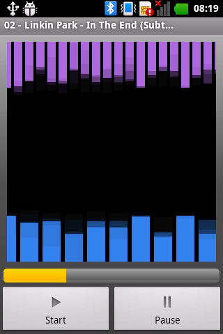
In this screen, through histogram charts, the frequency spectrum of the sound is displayed (the full band is divided into 19 sections for higher section and 10 in the lower one), furthermore, the upper end shows the name of the currently playing file. At the bottom, a scroll bar represents the execution time of the audio file and 2 buttons help you to start or pause the execution.
Clicking the Android menu button at the bottom shows the configuration selection menu that consists of four buttons: “Connect” to return to the scanning section and select the Hardware board to which to connect, “BT Config” to select the bluetooth configuration of the board; “Settings” to configure the audio threshold level and Finally, the “Open File” button to select which audio file to run (the selection is done through the folders and files on your smartphone)

In the first configuration page you’ll find an horizontal selection bar through which to choose the audio threshold level. By pressing “OK” the value is set; “Default” will get back to the default configuration. On the second page of the configuration, there are two configuration sections: “System Name” and “PIN code”; a text field is coupled with each section to set the configuration; a button requests sending and modifications of the settings.
On the last page (“Open File,”), you can pick the audio file to play. Starting from the root folder, the contents of the SD card are displayed; by clicking on a folder you go inside the sub-directory (“..”, “Parent folder” to return to the upper folder), by clicking on a valid audio file that is selected and the page gets closed (returning to the main window)
In the store
That’s all!
Light up your Christmas!

[…] The circuit diagram of a single expansion shield has been developed around the U1 component, namely Microchip’s MCP23017. Find more info in the previous post. […]