Let’s complete the construction of our aircraft and test it.
Now that you have physically created the quadcopter – according to the indications supplied in the first installment of this article (published here) – you may move on to the operational stages, and see as a first thing the commands available for our radio model and the customized settings in the remote control.
Commands via radio and calibrations
You have different commands available, that may be directly sent from the radio without the need to use the telemetry. Once the quadcopter has been powered, the propellers remain still and the motors are not powered; they are therefore “unarmed”. In order to give the commands and to carry out the calibrations you have to “arm” the quadcopter; that means to bring the propellers to the minimum rotation speed, while waiting for the climb command. We will see the commands that is possible to give as follows.
- Arming the quadcopter: this command is given with the right stick at the centre + the left stick down and on the right; the propellers will idly rotate. If the motors do not start and the LED remains turned off, there is a problem related to the receiver’s configuration. If the LED is turned on after the engines start procedure and they do not start, then the problem is to be attributed to one of the ESCs.
- Disarming the quadcopter: the corresponding command is given with the right stick at the centre + the left stick down and on the left; the propellers will stop.
- Gyroscope calibration: this command is given with the right stick down and with the left stick down and on the left; the status LED will turn on, and the buzzer will give off three beeps.
- Accelerometer calibration: it is achieved with the right stick down and with the left stick up and on the left; the status LED will turn on and the buzzer will give off a beep.
- Magnetometer calibration: this command is given with the right stick down and with the left stick up and on the left, the STATUS LED flashes quickly; you have about 30 seconds to rotate the quadcopter of at least 360° along all the three axes. Please start with the Z axis, the quadcopter being kept horizontal and rotated of 360°, then rotate it on the axis corresponding to the direction of travel (still with a 360° rotation) and, lastly, please carry out the rotation along the transverse axis. When the LED stops flashing (and the buzzer will stop giving off a beep), the calibration is ended and the corresponding data is saved in the EEPROM. The calibration must be executed with the quadcopter being far from every metallic element and operating electric component and, best of all, in an open field. If you are using the telemetry, the wireless one is better, otherwise the USB cable will get tangled.
- Barometer calibration: actually this one is not necessary, since the reference value for the height is memorized, at the moment in which the BARO function is activated.
- Accelerometer offset regulation (trimmer): this is given with the left stick up; with the right stick it is regulated (up, down, right, left). The STATUS LED will flash at every step.

Operating modes
The quadcopter supports different flight modes, depending on which sensors are used in the stabilization. We will describe them as follows.
- Arm (Acro Mode); this is the basic mode, having only the gyroscope available. No other sensor helps in the stabilization and therefore the control by means of the remote control is essential. It is possible to carry out sudden maneuvers and quick flights, but the quadcopter is sensitive to each electromechanic imperfection, and there are no sensors to compensate the flight attitude. This is the default mode when the HORIZON and ANGLE modes are not activated.
- Angle (Self Level Mode); also known as STABLE mode, it takes advantage of the accelerometer for the purpose of keeping the quadcopter levelled, that is to say: the tendency to drift towards whatever direction is compensated. The quadcopter is stable if the PID values are correct ones and the gyroscope and the accelerometer are calibrated.
- Horizon; this mode uses the accelerometer and the gyroscope in order to keep the quadcopter levelled when the sticks are released (stable flight) but it leaves the chance to execute sudden maneuvers when the sticks are used.
- Baro; when this mode is activated – by means of the reading of the barometric sensor – the quadcopter keeps his altitude unchanged. The accelerometer’s Z axis contributes to the stabilization, it also helps to sense the level variation.
- Mag; the magnetometer is used so to maintain a specific direction, and it compensates the inevitable quadcopter drift that brings it to spin around itself. By acting on the YAW command it is possible to command the quadcopter’s direction, but by releasing the stick it will always return to the initial position.
- Headfree (CareFree); this mode has been thought for the beginners, who are not used to “think” as the quadcopter does. This function uses the compass and the last known position, in order to command the quadcopter accordingly to the stick’s movement, and independently from the direction of the quadcopter itself. For the greatest part of the beginner pilots, in fact, it is difficult to direct the quadcopter if it is not perfectly aligned with the head and the front. If, as an example, the quadcopter goes towards the pilot and the latter moves the stick right, it will actually go to the left, since it is oriented with an angle of 180° with respect to the pilot. This mode is independent from the YAW control and the related stick may not be activated.
- GPS Home; in this mode the GPS is used in order to return the quadcopter to the initial position. It is appropriate to activate this function along with other stabilization functions, and specially to keep a predetermined height, since the GPS is not very accurate.
- GPS Hold; the quadcopter keeps the coordinates of the point in which the function was activated, and thanks to the altimeter it maintains the height.
In Table you will find a summary of the various flight modes and the sensors needed in order to implement them. By means of the radio auxiliary channels it is possible to select the desired flight mode; this is done by means of a firmware routine that associates a specific mode to a given range of values of the PWM signal. In the CT6 radio transmitter, that we used in order to command the quadcopter, the auxiliary channels are managed via a potentiometer each, which makes it very inconvenient to set the operating modes by means of them; for this reason in the first installment we told you to substitute a potentiometer (it is better to substitute both) with a 3-position deviator of the ON-OFF-ON kind, that guarantees the safe correspondance between the lever’s position and the desired mode.
Table

Once the modification is carried out, the selection of the operating modes is as follows:
- AUX2 deviator with the lever down = ACRO mode;
- AUX2 deviator with the lever in the centre = ANGLE mode;
- AUX2 deviator with the lever up = ANGLE+BARO+MAG mode.
The definition of these functions is carried out by using MultiWiiConf and by clicking on the small squares corresponding to the function you want to activate.
PWM outputs’ test
Let’s deal now with the verification of the outputs for the motors command, if they are properly functioning: let’s activate the outputs by bringing the left stick down and on the right, the outputs will be brought from a value of 1,000 to 1,150 and the STATUS LED will turn on, so to indicate that the quadcopter is armed. At a later stage we will have to be sure that with a signal equal to 1,000 our motors won’t run, and that with a value of 1,150 they will idly run. Please inclinate the board to the right and verify that the right signal will increase, while the left one decreases. By inclinating the board upwards it will be the front signal to decrease and the rear signal to increase; this is the effect of the stabilization induced by the accelerometer (with the ANGLE mode activated). if you activate the MAG mode you will verify the stabilization on the YAW axis: if you try to rotate the board (while saying on the plane) you will see that the DX-SX signals and the FRONT-REAR signals will compensate the movement.
Mechanical parts assembly
With the command board tested and operational, it is possible for us to finally deal with the mechanics. The quadcopter’s frame must be assembled, according to the instructions included in the package; it is important that the assembly is an accurate and exact one, please tighten carefully each screw.
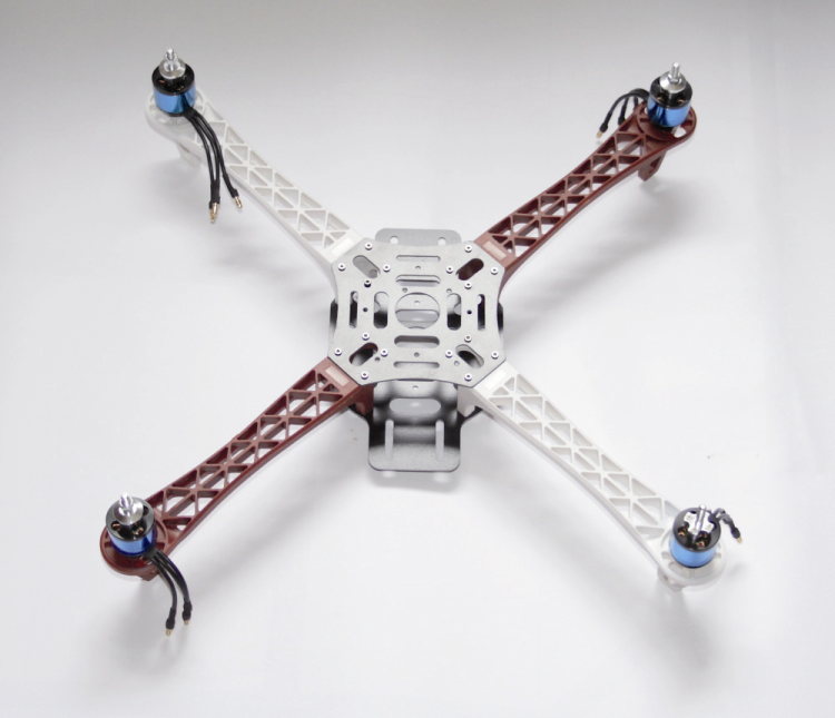
Afterwards, please block the motors with the specific screws and the related ESCs, by means of some small strips, in the inferior part of the frame’s arms, as shown in figure.

Please use the Power Distribution Board in order to connect the power source of all the ESCs to the battery cable; it is a board that is composed of tracks only, for the purpose of the distribution of the power on the side pads. Please don’t forget the small jumper that will bring the battery’s positive signal to the board for the purpose of measuring the charge level.
Above everything, please fix the control board, and preferably use plastic screws, for the purpose of avoiding both accidental short circuits and interferences with the IMU module; we will remember, in fact, that the magnetometer is sensitive to the presence of metal.

On completion of the work, the quadcopter – comprehensive of the battery having the expected capacity – weighs around 950 grams: a weight that is definitely inferior to the one that the four motors with the related propellers are capable of lifting. This allows us to take advantage of this loading “reserve” and mount a small video camera on board, with which to carry out some aerial shootings.
Connection of the motors
The quadcopter is assembled in QUADX mode and the ESCs must be connected to the board in the following manner:
- SX front motor to the D2 pin;
- DX rear motor to the D3 pin;
- DX front motor to the D5 pin;
- SX rear motor to the D6 pin.
If the ESC uses a BEC of the LDO type, as in our case, it is possible to connect all the outputs without carrying out modifications. If the BEC is of the switching kind, it is important that only one of the ESCs brings power to the board. In this case, please remove the red wire from each ESC’s cable, with the exception of the one that will power the board.
Now you will have all of the mechanics and electronics assembled; there are only the propellers left to be mounted, however at the moment it would be better not to apply them to the motors, since their presence may create a dangerous situation. Please connect the battery monitor’s jumper to the AOV input, and then proceed to start the system for the first time, and connect the battery to the connector that brings to the distribution board; you will hear some beeps coming from the ESCs and two power LEDs of the board will turn on, in addition to the power supply LED of the IMU module.
ESCs’ calibration
At this stage you will have to deal with the calibration, an operation that is very important since it sets all the ESCs so that they will operate in the same way.
The calibration may be carried out – in a very simple way – by means of the MultiWii software.

The operations to be carried out are:
- please activate the la funzione ESC_CALIB_CANNOT_FLY function, while in the MultiWii software, by removing the comment characters in the #define ESC_CALIB_CANNOT_FLY line of the file;
- please verify to not have mounted the propellers on the motors and, in the case you did it, remove them (still with the battery detached!);
- please power the quadcopter via the ESCs and the motors connected to them;
- once you are ready to start the calibration, please load the sketch in the quadcopter’s control board;
- once the sketch has been booted, the calibration starts, and its ending will be signalled by the LED STATUS being turned on;
- please comment the #define ESC_CALIB_CANNOT_FLY line and reload the sketch;
- the calibration is concluded and the ESCs are ready.
Please notice that, if needed, the maximum and minimum calibration values may be modified by intervening on the ESC_CALIB_LOW and ESC_CALIB_HIGH lines.
Vibration test
The gyroscope and the accelerometer are very sensitive to the vibrations, but for our application it is necessary that the data corresponding to their readings are free from alterations and falses due to the noise, and particularly to the ones induced by mechanical vibrations, otherwise it will be impossible to stabilize the flight; if there are too many vibrations, they will be transmitted to the gyroscope, that will not supply reliable measures any more. It is not possible to minimize the vibrations problem, therefore it is necessary to face the problem even before any flight test.
The solution for reducing the vibrations is to have a very rigid structure: aluminium, fiberglass, carbon-fiber chassis are generally much less prone to vibrations in comparison to those in printed plastics or Lexan (this material is a polycarbonate). The coupling of the board to the chassis is very important and it must be carried out so that the gyroscope is capable of detecting the small movements of the chassis; however it must not be too rigid, otherwise the vibrations created by the motors will be transmitted to the gyroscope with their full intensity.
When constructing our prototype, we opted for using nylon screws that have rubber washers, when fixing the board to the chassis; moreover a covering has been placed over it, so to prevent that the turbulence of the air induced from the propellers may bring further vibrations on the board.
The vibrations are essentially due to mechanic imprecisions, that is to say, to the bad balancing of the propellers and the motors; in this case, the usage of quality products makes a difference. In order to verify the state of the vibrations it is possible to activate a particular section of the MultiWii software: when in the usual config.h file please remove the comments from the #define DYNBALANCE line and load the sketch on the board; in the upper part in the MultiWiiConf software, please click on MOTORS and a new section will open, that allows to check each motor individually, by means of a pointer activated via the mouse.

You may carry out the first tests without the propellers and verify the presence of possible vibrations due to loosen joints or unbalanced motors. On the main panel please select the visualization of the accelerometer’s data only, so to have a diagram that is easier to read. As for the balancing, we find it valid to use some small pieces of insulating tape, that are slightly thicker than the typical scotch tape used in the offices; the insulating tape must be applied to the rotor’s external part. Try to apply it to various positions (after all it is easily removed) until you find the point in which the vibrations are minimal and then try to work on the quantities, so to eliminate them.

Once the best balancing possible has been found, you may verify the correct rotation of the motors: the one in front and the rear one will have to rotate in a clockwise direction, while the right and left one will have to rotate in a counterclockwise direction. The next step is the installation of the propellers, an important step given the intrisic danger of having four propellers, sharp as razors, that spin at ten thousands revolutions per minute! The front and the rear propellers have to rotate in a clockwise direction (CW) while the right and the left ones will have to rotate in a counterclockwise direction (CCW); please remember that when the propeller rotates, it must push the air downwards. Please activate one motor at the time, and bring the stick to about halfway; please pay the highest attention since the quadcopter will start to take off and therefore you will have to try to somehow hold it down in order to avoid it causing damages or, worse, to hurt yourself! In the telemetry settings, please leave the only visualization of the accelerometers and possibly zoom on the diagram’s scale, so to better see its details. In this case, the insulating tape must be applied to the back of the propeller. By clicking up in the SETTINGS section, you will be able to see the settings related to the battery alarm and the setup related to the motors’ command.

Activation of the wireless telemetry via Bluetooth
It is possible to enable the wireless telemetry by means of a Bluetooth communication, in a simple and fast way, thus allowing the compatibility with PCs, smartphones and tablets. You will need a Bluetooth module of the slave kind, that is enabled for the SPP profile (serial communication) as the HC-05 or HC-06 modules are, or the DAGU module. The essential step is to modify the communication speed, by bringing it to 115 Kb, the assigned name is inconsequential.
The PC on which the MultiWiiConf software will run must have an appropriate integrated Bluetooth module or a dongle, inserted in a USB port, that will be able to connect to the board; given that the communication is in transparent-mode, nothing changes in the software management.
Let’s see now the steps to follow in order to use the Bluetooth module, by referring to the DAGUS model, that is essentially a HC-06 module with Linvor V1.8 firmware. Please use a USB/Serial converter in order to interface the module to the PC; with the wiring as follows: Vcc-Vcc, GND-GND, TX-RX, RX-TX.
Please start a software for the serial communication, such as Termite (free software that does not need an installation) or, in a much simpler way, you may use Arduino IDE. Please open a communication towards the port in which the USB/Serial converter is installed and set a communication speed equal to the module’s default one (usually 9,600 bps); in the transmission, please disable the addition of the carriage return and of a new line (CR and LF). Please send the AT command and wait for the OK reply in order to verify that the module correctly replies; if it wasn’t like that, try to set other communication speeds and repeat the sending of the AT command. Once the connection has been established, please give the AT+VERSION command, in order to visualize the firmware version installed.

You may modify the device name by means of the AT+NAMEmyname command and finally, please modify the communication speed by means of the AT+BAUD8 command; at each command you will receive a confirmation reply. The abovesaid settings may be carried out only with a disconnected module.
The red LED is turned on along with the powered module, while the blue LED flashes while waiting for a connection; it remains with a fixed light when the module is connected and ready for the transmission. From the remote device it is necessary that you execute the association with the Bluetooth device: the password to be typed in, when required, is 1234.
If you are using the BT HC-05 module, FC-114 version, you will have to proceed in a slightly different way: please connect the module to the PC via a USB/serial that works at 3.3 volts and manage the communication by means of any software for the serial monitoring, and pay attention to set the mode for sending commands, with the addition of the carriage return and of a new line (CR and LF).
Please enable the module’s AT command mode and send the AT string so to verify that the communication is ok; you may use the AT+VERSION command in order to verify the installed firmware version. We are interested in modifying the communication speed, by bringing it to the value of 115,200 bauds, which is obtained by sending the AT+UART=115200,0,0 command (the name of the device is inconsequential).
On the flight board, two connectors that may be used for the telemetry are available; both are connected to the microcontroller’s UART3 module. The connector marked as UART3-5V is suitable for telemetry systems operating at 5V, such as DAGU’s Bluetooth module, while the connector marked as UART3-3V3 is suitable for circuits operating at 3.3V, such as the HC-05 Bluetooth module.
As an alternative, on the board there is a socket on which it is possible to directly weld the HC-05 module. The HC1RX and HC1TX jumpers must be placed towards contact 3 (UART3).
Management via APPs
If you have equipped the board with a Bluetooth module, you may activate the wireless telemetry by means of a smartphone (or tablet) via a specific app. The convenience offered by such an option is to have a compact and light device available, one to carry with us in the flight field. The currently available apps are the MultiWii Configuration Tool and the EZ-GUI Ground Station, however only the latter is compatible with the last software version (V2.4); it may be freely downloaded from the official Google Play store.
With this app you will be able to visualize the status of all the parameters in real time, and to remotely set the PID parameters in a safe way, during the flight a vocal assistant will inform you of the operating state, and refer about possible alarms; still by means of this app, assisted flight with the help of GPS and the mission planner are possible.

In order to use the telemetry via Bluetooth, as a first thing please associate your BT module with your device, be it a smartphone or a tablet: at a later time download and start the EZ-GUI app. The first setting required is the name of the BT module to which to connect, different other settings follow, but the default values are fine as well.

The app has three sections: the first one is named Dashboard and it allows the visualization of all the flight parameters, the second one is named settings that allows to set the values for the PID and the AUX inputs, the third section is named Configurations and allows to set the app functions.

We will not describe all the details of the application, also because it proves to be very simple and intuitive; we advice only the activation of the vocal assistant, a very useful function given the impossibility to take off the eyes from the quadcopter. This application also manages the mission planner with the assisted flight via GPS.

An alternative to the MultiWiiConf software
Until Multiwii’s penultimate version, the mission planner was not implemented, and in order to fill this gap, the related community made an alternative software available for Windows operating systems, which is named MW-WinGUI: in addition to more captivating graphics, the program implements different additional functions as regards the mission planner. The reference website for the MW-WinGUI.
The version for Multiwii 2.4 is not yet available, it is however possible to use the MultiWii 2.3 navi b7 version, by setting the previous version in the Multiwii.h file; this is done by editing the file and by writing the following instruction: #define VERSION 230.
Before the flight
Well, given that the topic of the software has been exhausted and that the construction of the quadcopter has been defined, we will cover now the real purpose of this article: to have a RC model to fly. Therefore, let’s get ready for the maiden flight.
We will give for granted that the motors/propellers groups are balanced and that they run correctly; please verify that the radio channels are centered at 1,500 ms and we will have a range such as to significantly exceed the MINTHROTTLE and MAXTHROTTLE values. The battery must be securely fixed on the frame’s lowest part, and perfectly aligned with the barycentre; please make sure it does not move. Please raise the quadcopter by picking it up from the fulcrums of two motors taken on a diagonal, so to verify that the weight is perfectly balanced: if it leans from a side, please move the battery until you sense that it is balanced.
Please place the quadcopter in a perfectly levelled zone, and calibrate all the sensors, then move in the flight area: grass lawn would be better, as it may soften a possible fall. Please make sure that all around you there are no persons or animals, and place yourself in a position of the maximum security; also, please pay attention to the flight rules imposed by Local Authorities. Please remember that each aircraft flies with respect to the air and not to the ground, therefore in the presence of wind the quadcopter will tend to follow the direction of the latter, and even small gusts may seriously influence his stability; we advice, therefore, to carry out the first flights in the absence of wind.

The maiden flight
Please disable all the flight modes, so to leave only the gyroscope active, and arm the quadcopter. Please activate the acceleration stick slowly, and make the quadcopter take off – still paying the highest attention, since you are using the default PID values and it is not said they are correct ones. Within 50 cms from the ground, the air turbulences may significantly influence the flight, therefore be ready to compensate the possible deviations, and as soon as you can let the quadcopter climb more.
In our first flights we used the ANGLE mode, that uses the accelerometer in order to stabilize the flight and make the piloting easier, even for the beginners. The default PID values (P=3.3 I=0.03 D=23 for the ROLL and PITCH and P=6.8 I=0.045 D=0) proved to be good already, but it is possible to further optimize the stability by means of small and focused adjustments.
The flight at very low altitude (20/30 cm from the ground) is affected by the cushion of air created below, that makes the quadcopter drift (hovercraft effect). At a meter of height, the quadcopter is not affected by turbulences and the flight is more regular, but the risks of causing damages in the case of a fall increase; if you see that the quadcopter behaves strangely or that it tends to get too far too quickly, do not panic and slowly reduce the acceleration in order to make it descend.
In the ANGLE mode the flight is more stable, but if you sense a tendency to drift away somewhere, please take care of the accelerometer’s regulation, as previously described.
Once you have obtained a satisfactory stabilization, and only small adjustments of the sticks are needed in order to keep it in position, you may activate the magnetometer and the barometer as well. Please activate the BARO function once you have reached the desired altitude (and you want to keep it); in that moment the reference value will be memorized and you will be able to take away the finger from the throttle stick. You will still have the control via the stick, but if you want to land you will have to disable the function.

PID parameters calibration
The P (Proportional) parameter is the gain, that is to say how much the stabilization sensors intervene; it is important that it is as high as possible, so to have a very stable vehicle that tends to contrast decisively every attitude variation, but it must not be an excessive value, otherwise the vehicle will enter an oscillation state. The I (Integrative) parameter intervenes in the long run to compensate attitude errors, and tries to help the quadcopter to keep the position given by the sticks. The D (Derivative) parameter is influential when some sudden attitude variations occur. By raising this value, the quadcopter is helped in softening the oscillations that occur when there are attitude variations due to sudden maneuvers; but it also compensates the influence of the wind gusts, somehow. Please pay anyway attention to not exaggerate, since too high a value of the D parameter will induce dangerous oscillations.
Presuming to start with an already good set of values, it will be enough to correct them during the flight tests; the PID parameters must be modified, little by little and with extreme patience, with steps of ±0.2 as for P, of ±0.005 as for I and of ±1 as for D. When setting or adjusting the PID parameters, please keep in mind what follows.
- With high P values, the quadcopter has a considerable strength to resist whatever attempt to move it, however excessive values involve oscillations at high frequency and, at most, instability. In the aerobatic flight, higher P values are preferred.
- With low P values, the quadcopter is less resistant to the attitude variations and shows the tendency to drift. During the regular flight, lower P values are preferred.
- With high I values, the capability of keeping the initial position and to reduce the dispersal is increased, but the delay with which it returns to the initial position as a consequence of an attitude variation is increased as well. During the stationary flight, higher values are preferred. If the value for the I parameter is too high, it causes low frequency oscillations.
- Low I values improve the reaction to changes, but they increase the drift and make it difficult to keep the position. During the aerobatic flight lower values are preferred.
- High D values improve the speed with which the disturbances are recovered; too high values induce oscillations. In the aerobatic flight, higher values are preferred.
- With low D values, the oscillations at the return to the initial position are reduced, but the movements are slowed down. During the stationary flight, lower values are preferred.
If you want a clearer idea of the influence of the PID parameters on the quadcopter’s flight, we advice you watch a YouTube video that is a very significant one; it is found at the following address:
During the calibration of our quadcopter, we slightly corrected the PID values as for the pitch and the roll, in addition to lowering of 50% the PID values for the altitude hold function.
CONCLUSIONS
In the end, we obtained a quadcopter showing good quality and performances, that is suitable to the outdoor flight, even capable of carrying small weights, and that represents a valid alternative to the toy models.
To the basic functions you may add other ones such as the GPS for the assisted navigation, to which it is however necessary to implement a ground station, with a long range wireless telemetry station.
Another function that is always more implemented in the quadcopters is the FPV (First Person View) flight, in which the images shot from the video camera aboard are reproduced in special glasses; this allows to drive without seeing the drone, as if we were really aboard.
In conclusion, satisfy your fancy and, above all, have fun!

From Openstore
RC Transmitter & Receiver 6 channels 2,4 GHz
FTDI USB-serial converter- 3,3V e 5V
Extension cord for servo – Lenght 150mm
HC05 Bluetooth Transceiver – SMD module
LIPO charger and lithium-ion battery
Crius – Connection tab to power multicopter
GY-86 flight control sensor module for multicopter
