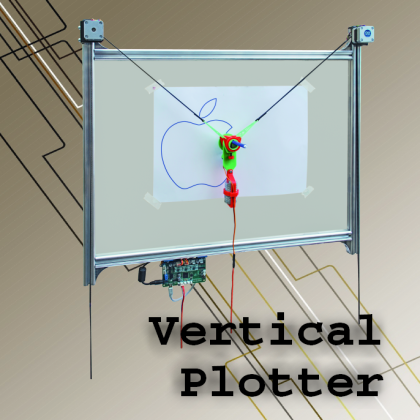
Let’s draw freely, by means of a plotter that is easy to make, using the same electronic board present in our 3Drag printer.
The vertical plotter is a kind of printer that is very much appreciated by professionals, since it does not print but draws by means of pens, and exactly in the same way a person would do with his hand; it allows to draw diagrams and sketches of various kind and with the maximum resolution, since it composes texts and images with a continuous line (and not with a dot matrix, as the impact, laser and inkjet printers do).
Today we would like to propose you a low cost version, that has been made inexpensive by the availability of cheap stepper motors and of an open source controller board, that in our case is the same used for our 3Drag 3D printer (even though it was provided with a modified version of the original firmware); the chassis is left to your personal preferences, so you may create it as you see fit: it could be obtained by attaching the two motors to a wood frame even, and by connecting the print head with a toothed belt and by providing the whole with counterweights.
The whole project is an open source one, and the version we created and proposed in these pages is just a personalization of the original idea. Even the firmware is an open source one and the software to be run on the PC (needed in order to command the plotter) may be freely used.
But let’s proceed in an orderly fashion, by spending a few words on the subject of the mechanical structure, that is essentially composed by a chassis frame, that we created with aluminium extrusions with a square section (side: 27.5 mm); the whole frame is 74.5 x 64.5 cm big, with the sides embossed on the superior side, with a height of 64 cm and ending with specific plastic “caps”. Each horizontal extrusion is 69 cm long, and to the side the vertical extrusions are fixed by means of angular screws; therefore it turns out that the total width is 2×27.5mm+690mm, that is to say they are exactly the aforementioned 74.5 cm.
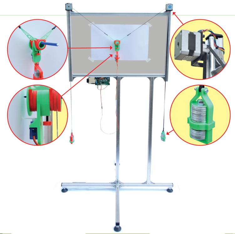
At the top (that is to say, at the upper angles) two NEMA 17 stepper motors at 200 steps/revolution are fixed, each one having a toothed pulley applied to the axis (and tightened by means of a hexagon socket screw) on which an opened belt goes by; the latter is composed of two segments, and it hangs on both sides and is opportunely stretched (so that it may adhere to the pulleys) by means of counterweights that are formed by a certain amount of 30 x 10 mm washers, each one being 2 mm thick. The counterweights are fixed by means of a screw passing through the eyelet that has been purposely made at the corresponding end in the toothed belt.
Actually, the belts are two fragments and in the middle of them a print head has been fixed: it is composed of a cylinder in which the pen is inserted, and fixed by means of a metal screw (in the next page you may see it in detail) that is provided with a plastic knob so to easily tighten it with a hand; a servo command with a plastic lever allows to push away and let the pen get closer to the sheet, respectively when there is need to draw or not.

A piece of the belt starts from one of the ends of the print head, it turns around the toothed pulley of a stepper motor and hangs on the side, and is kept tightened by a counterweight that is screwed to it; the other piece starts from the opposite side, it turns around the pulley of the other motor and hangs on the opposite side, even in this case it is kept pulled by means of a counterweight. The end of each belt’s portion creates an eyelet within which the screw that holds the counterweight is entered.
In order to ensure that each belt’s portion is being tightened, at the basis of the print head there is a further counterweight that, along with the head’s mass, balances the tension of the side masses; this detail is very important because if there was no central mass, the head would be raised and always brought up, with the part attached to the belt being aligned to the upper part of the stepper motors’ pulleys.
The print head’s mass has the function to bring down the pen when the motors reduce the belt’s tension, that is to say to have it move down and sideways, depending on which one of the two motors carries out more steps; on the subject we would like to point out that, in order to have the print head move on a side, the motor of the corresponding side has to rotate towards the internal part more than it does on the opposite side.

The penholder print head has two triangular wings, so to secure it to the belt; it has been 3D printed by means of our 3Drag printer and you will find the files on thingiverse, along with those needed in order to create the counterweights’ cases.
The counterweights have to be chosen so that the print head remains in the right position, even with unpowered motors, and they must have a weight such that they allow the belt to adhere to the pulleys’ teeth, so that it will be them to move or brake the belt itself, and the print head with it. As we could see, in our vertical plotter we used some washers as a counterweight. This way it is easy to calibrate the weights and to choose an adequate number of washers.
The motor in the corner up and on the left is connected to the output for the X-Axis motor of the 3Drag controller board, and the one up and on the right to the output of the Y-Axis motor of the same board; the servo command is managed by the X-STOP connector of the usual controller board, that in this case is configured by the firmware so to operate as an output, instead of as an input.
Naturally the chassis that we created is not a mandatory solution, and you may create it of the size you prefer (by adjusting the software parameters concerning the print head’s travel) as well as build it as you prefer: for example in wood, or by using a picture frame, or by applying the stepper motors at the upper corners of a plank, and by making the pulleys stick out (to them the belt system, the print head and the counterweights are to be fixed).
Once the mechanic part has been completed, it is possible to carry out the few required wirings, by respecting the wires’ colors, as indicated in the drawing that you see in the previous pages.
The 3Drag controller board has to be programmed by means of the specific firmware.

The loading of the firmware is carried out by connecting the board – via USB – to a PC in which the Arduino IDE has been installed; in fact the controller board is based on Arduino Mega’s hardware.
Afterwards, please open the downloaded firmware’s file (.pde), and select the board’s COM port, and choose Arduino Mega2560 as a board, then press the programming button. After a few seconds the board is ready for the usage.
The management software
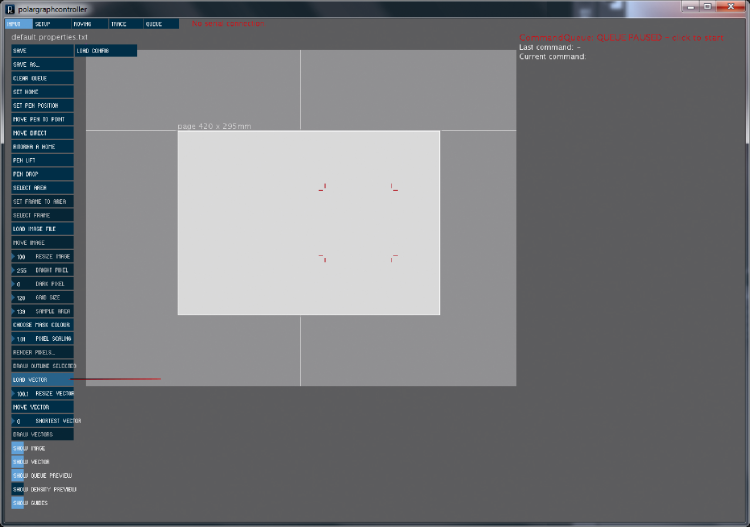
In order to check our plotter we chose the Polar Graph program, that may be downloaded: actually, the one we used is a customized software that we have developed and it has to be downloaded from our website, along with the other project files (among which the firmware used in order to manage the plotter) and the libraries, in addition to the Processing file. All of this is available under the form of a compressed archive: once it has been downloaded it must be unpacked and some folders will be obtained (all of them are contained in the “Vertical plotter” folder). One of them will contain Processing, version 1.5.1 (that’s the one to be used): the program (in the Processing folder) and the source files (in the Processing Source folder). Please open the latter, inside of it you will find the polargraphcontroller.pde file, that is placed in the Vertical plotter\processing\Processin-source\polargraphcontroller path, you have to double click on it. This way you will boot Arduino’s IDE, and this screen will appear, and it wil show you the corresponding listing. By clicking on the Play button (the arrow up and on the left in the IDE commands bar) you will be before the program’s window. This means that the program has been started.

How to connect polargraph to the PC
If the plotter is not connected to a PC – when we start Polargraph Controller – it won’t be detected: the words “No serial connection” will appear up and on the left. At this stage we will connect the USB to the PC, and will wait that Arduino drivers are installed, then will open polargraph controller; if the words “Polargraph READY! (arduino version)” words do not appear, it is needed to go in the SETUP tab and click on the last entry in the “SERIAL PORT…” column. At this stage we will select the port assigned to our Arduino (in this case, COM 8).
How to configure the vertical plotter
The first thing to do now is to configure the plotter, that is to say, to define the parameters of our mechanical part, so that the program may know it and know how to regulate the print head’s movements. As for the configuration, let’s go to the “SETUP” tab and click up and on the left, at the specific menu entry. As a first thing, please type in the circumference of the pulley mounted on the motors, in “MM PER REV”: in our case it’s 40. After that, please set the numbers of the motor’s steps/revolution in “STEPS PER REV”; you will have to be careful with this step, since a mistake will make the print head go out of the “frame”. The NEMA 17 motor (the one we used) has 200 steps/revolution, but with the 3DRAG controller board each step is divided in 16 micro-steps, so in order to obtain the total number of steps per revolution to be inserted, we will have to multiply the number of the motor’s steps by 16 (200×16=3.200 steps). You will now have to set the machine’s size. MACHINE WIDTH is the distance among the closest points of the stepper motors’ pulleys, while MACHINE HEIGHT is the distance between the imaginary axis that joins the motors’ axles and the chassis’ lower side, that is to say of the area that may be drawed. In order to set the size of the sheet we want to print, we will have to type in the values in “PAGE WIDTH” and “PAGE HEIGHT” that respectively are the page’s width and height. You will now have to set the size of the pen’s (or felt pen’s) tip you want to use in “PEN TIP SIZE” and then click on “SEND PEN TIP SIZE”. Please insert the pen in the print head and fix it by means of the specific screw, however you will have to be careful that the distance between the print head and the sheet is not greater than the length of the servo arm used in order to lift the print head from the sheet. Once all of this has been done, please remember to click on “SAVE”, in order to save the settings in a permanent way, and on “UPLOAD MACHINE SPEC” so to write the settings in the EEPROM microcontroller, in the case you wanted to download them you would have had to click on “DOWNLOAD SIZE SPEC”. If the printing turns out to be too slow or too fast, it is possible to act on the maximum motors’ speed and on the acceleration. By raising “MOTOR MAX SPEED” we will raise the motors’ maximum speed, while by decreasing it we will decrease that speed. By raising “MOTOR ACCELERATION” we will decrease the acceleration, and by decreasing it we will increase the acceleration.
How to load and print a vector
We will now make a print: as a first thing please click on “LOAD VECTOR” on the left column, once a dialog windows opens (in which to select the file to be opened).
Once the file (in the path it is located) has been chosen, please click on “Open” and the corresponding image will appear in the dialog window. After that please click on “SELECT AREA”, so to select the area on which you want to draw the vector and then click on “SET FRAME TO AREA”. It is now possible to move and resize the vector at leisure, by means of “MOVE VECTOR” and “RESIZE VECTOR”. In order to print the vector it will be enough to click on “DRAW VECTOR” so that the coordinates needed in order to draw the vector will be created; now it will be enough to just click on “QUEUE PAUSED” (the caption is in red and up and on the right), it will become green and will change in “QUEUE RUNNING”.
How to load and print an image
Please click on “Load image file”, in the left column.
Please select one of the examples in the “examples” folder and click on open. In the case you made a mistake when opening, please click on “clear image” and repeat the operation in order to open another one. In our case we will use apple logo. Once opened, please click on “MOVE IMAGE” and place the image wherever you want in the white area that corresponds to our sheet; once the position has been reached please click on it and then click again on MOVE IMAGE, so to deactivate the tool. If the picture is too big for the sheet, or if we want to make it smaller or bigger to our liking, we will have to click on “RESIZE IMAGE” and drag the mouse upwards in order to make the picture smaller, and downwards in order to make it bigger. Even in this case, once the operation has been completed please exit the tool by clicking again on RESIZE IMAGE.

Once the picture has been placed, please click on “SELECT AREA” and select the picture’s area that you want to print, and then click “SET FRAME TO AREA”. It is now possible to act on several picture’s parameters and therefore to create a style for the picture that will be printed.
- BRIGHT PIXEL will act on the amount of light pixels found in the photograph;
- DARK PIXEL will act on the amount of dark pixels found in the photograph, by default this value has been set to the minimum (0).
- GRID SIZE: by modifying this value you will act on the pixels’ size, the greater it is, the bigger the pixels will be (and the bigger the pixels are, the less the time needed by the plotter in order to print the drawing).
- SAMPLE AREA: by modifying this value, the pixels’ density will increase or decrease (the greater this value is, the more the time needed in order to print the drawing).
Once these parameters have been set at leisure, it is possible to click on RENDER PIXEL and a dialog window will open, in which to choose the filling style as for the image. In the first column it is possible to choose where to start the pen, as for the printing:
- up and on the right;
- down and on the right;
- down and on the left;
- up and on the left.

In the second column on the right it is possible to choose the writing mode for the pen:
- VARIABLE FREQUENCY SQUARE WAVE; the pixels are drawn in a square wave form, in order to draw the darker parts the wave frequency is increased;
- VARIABLE SIZE SQUARE WAVE; instead of increasing the square waves’ frequency, the size of the squares drawn is increased;
- SOLID SQUARE WAVE; this one is used in the case different colors are used (the line is always in a square wave form, but it is constant);
- SCRIBBLE; the line’s form is one as if there were disturbances, it is a totally random one (within the pixels limit); in order to draw the darker areas more lines are drawn;
- SPIRAL; the pixels are drawn in a spiral form;
- SAWTOOTH; the line has a sawtooth form.

In the last two lines it is possible to choose:
- LIFT PEN OVER MASKED PIXEL that is to say, the pen is lifted when there are masked pixels; it is possible to choose the color of the masked pixels by clicking on “CHOOSE MASK COLOR” in the usual menu, and then by selecting the core as for the pixels you want to mask;
- DRAW MASKED PIXEL AS BLANKS; where there are masked pixels, they are drawn as blank spaces.
After having selected the desired options, please click on “GENERATE COMMANDS” and the coordinates for the pen will be created.
How to print the edge only
In order to draw the image’s edge, it is enough to simply load the image, to place it where you prefer, to select the area and the frame, afterwards please go to the “TRACE” tab. It is possible to modify three parameters:
- BLUR = distances among the lines;
- SIMPLIFY = how much do you want to simplify the image;
- POSTERISE = in order to create more harmonious lines.

Video
From openstore
Stepper motor NEMA17 – 1,8° – 0,28A
SUB MICRO SERVO 9g – 22x11x29 mm

[…] Open Source Vertical Plotterxyz […]
[…] Open Source Vertical Plotter […]
Do you have a link for the 3D print files on Thingiverse?