
.


Connected to a burglar alarm or fire alarm in the event of making phone calls playing voice messages. Controlled via DTMF actuators can operate on the spot.

In recent years we have introduced several telecontrols based on the SIM900 GSM module. We released schematics and code for a gate opener (that activates when receiveing a call from a given number), a GSM thermostat to manage the temperature of remote houses with simple text messages, a remote alarm control with DTMF and, last but not least, a remote alarm with I/O and controlled via calls or SMS.
Many of these tools send text messages or place phone calls in response to changes to the electrical inputs. In some cases, especially when the receiver is a human, nothing is like a voice that clearly yields you screaming “fire in progress!”, or”thieves in the house!” etc. …
That’s why – and also since we love things that speak (see our Voice shield for Arduino) – we decided to design a remote alarm, with text to speech capabilities and able to send DTMF commands (which allows quick and easy remote configuration).
This device can be controlled by the phone keyboard and only accept calls from a defined group of numbers (8) that must be stored in the device or from any number, as long as a password is provided. Controls are there for management for output relays, inputs, as well as for some operational settings.

The Main board
The most attentive of you will have noticed that the schematic is missing a component, ie: the DTMF decoder…where’s the mystery? Well, we can do without 8870 (the decoder that always equipped our telecontrols in the past) because since few months SIM900 module can directly handle DTMF decoding. This means that all new SIM900 are able to inform the microcontroller and clearly distinguishing a DTMF two-tone from another.
Also our breakout boards with SIM900 have this feature.
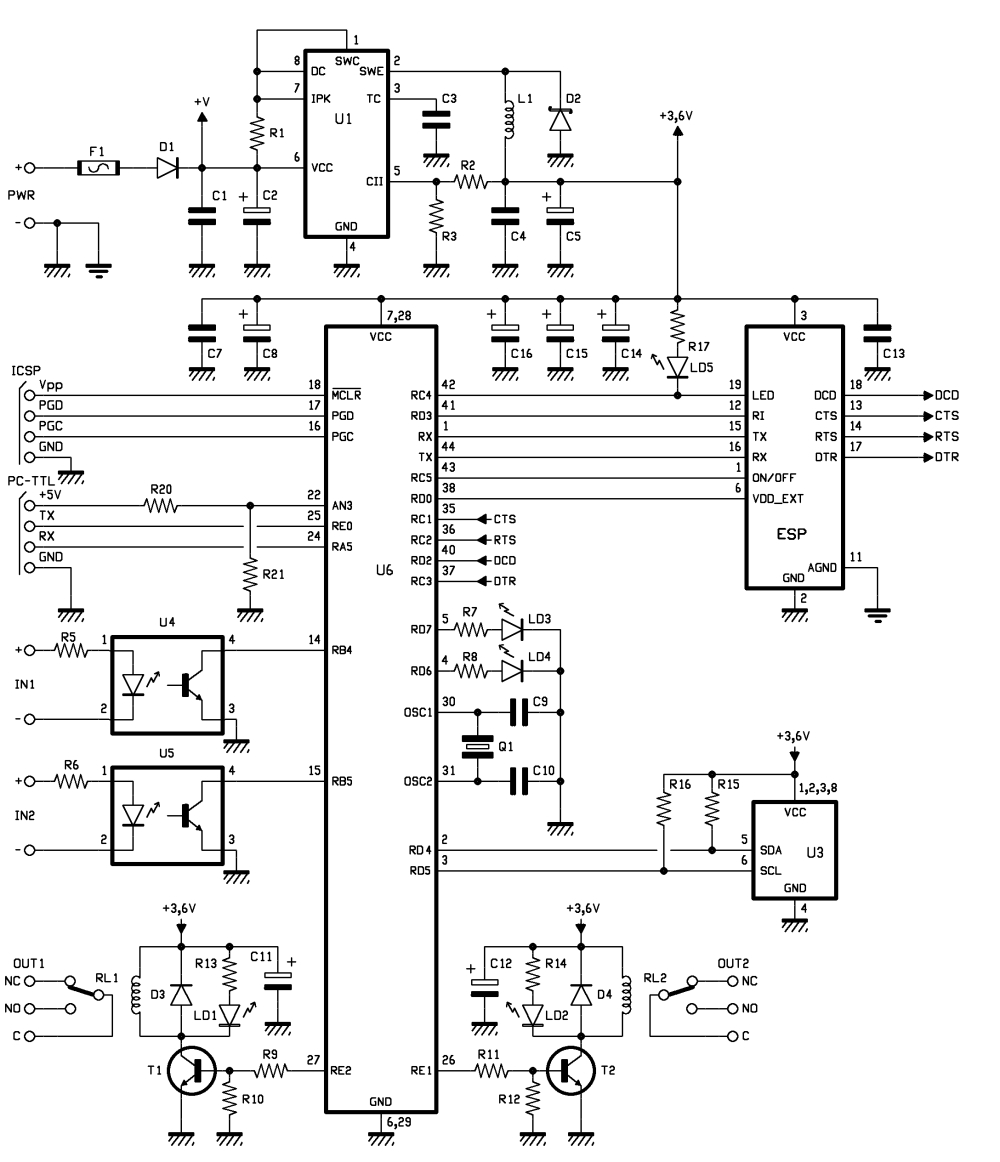
Well, let’s start with the analysis by the main component, ie the microcontroller that manages the GSM / GPRS module, checks the logical conditions of the two opto-isolated inputs and controls the two relays. Power supply is not stabilized DC voltage (applied to points named +PWR and -PWR) its value is between 9 and 32 V; it is filtered downstream the D1 protection diode from polarity inversion by means of the C1 and C2 capacitors. F1 fuse allows to protect the circuit and the power source in the event of a short circuit in the integrated controller that follows.
The microcontroller, the speech synthesis modules and GSM modules, as well as the rest of the circuit, are made to operate at 3.6 V, derived from a switching (U1) based on MC34063 integrated and used as series PWM regulator with inductance winding.
The UART inside the PIC18F46K20-I/PT, is accessible from pins 44 (transmission) to 1 (reception) and is used to give commands to the mobile phone and the voice module, sharing the same bus; the GSM module is cyclically interrogated using the TX in order to verify SMS arrival, while TX and RX together serve, during calls or messaging, to communicate between the microcontroller and the GSM module. With regadrs to the voice module, TX imparts commands and RX reads incoming data.
The GSM is also managed via RC5 and RD0: the first controls the on/off switch (via a transistor in mobile base), the second resets the mobile module.
The CTS (Clear To Send), RTS (Request To Send) and DCD (Data Carrier Detect) are actually not used as such, but they instead form the four-wire SPI bus the microcontroller uses to communicate with the speech module. The voice module is mounted on the base board and, upon it, it takes place the phone circuitry.
Now let’s see the alarm inputs read by the RB4 and RB5 I/O, both configured as input and provided with internal pull-up resistor; each reads the state of the output transistor of the corresponding optocoupler. Each input (IN1 and IN2) is active when subjected to a voltage value between 3 and 30 V. The collector of each optocoupler is connected to a pin of the microcontroller (14/U4 and 15/U5).
Once a 3 volts voltage is applied to IN1, the photocoupler lites up the LED and the phototransistor output is into conduction, so that the (pin 5) collector is about zero volts, as a result of the fall on the internal pull-up resistor configured during I / O initialization. If the input is not polarized, the optocoupler is forbidden and its pin 4 is at high.
As for the relays, those are controlled by RE1 and RE2 lines, using two NPN transistors used as current amplifiers. RE1 and RE2 respectively T1 and T2 transistors. Activation is indicated by a LED powered in parallel to the coil.
Let’s see how to communicate with a PC for configuration: a serial interface is provided which can be applied to the TTL / USB converter to interface the unit via USB. Having already used UART to talk with the cellular module, serial communication takes place via lines RE0 and RA5, respectively exploited as TX and RX. AN3, assigned to the internal A/D converter, is used to detect the 5 volts (the insertion of the connector into the computer).
The USB / TTL converter we suggest is the FT782M, already used in other projects.
Configuration data is stored in an external 24FC256-SN memory, a 256 kbit EEPROM CMOS with I²C-Bus interface. To interact with it, the microcontroller uses RD4 and RD5, initialized to operate respectively as SDA (data line) and SCL (clock line).
BOM main board
[code]
R1: 0,1 ohm 1W (1206)
R2: 2,2 kohm (0805)
R3: 1,2 kohm (0805)
R4: –
R5: 4,7 kohm (0805)
R6: 4,7 kohm (0805)
R7: 330 ohm (0805)
R8: 330 ohm (0805)
R9: 4,7 kohm (0805)
R10: 10 kohm (0805)
R11: 4,7 kohm (0805)
R12: 10 kohm (0805)
R13: 330 ohm (0805)
R14: 330 ohm (0805)
R15: 1,5 kohm (0805)
R16: 1,5 kohm (0805)
R17: 330 ohm (0805)
R18: –
R19: –
R20: 1 kohm (0805)
R21: 2,2 kohm (0805)
R22: –
R23: –
R24: –
R25: –
R26: –
R27: –
C1: 100 nF (0805)
C2: 1000 µF 35 VL
C3: 100 pF (0805)
C4: 100 nF (0805)
C5: 100 µF 16 VL
C6: –
C7: 100 nF (0805)
C8: 470 µF 6,3 VL (CASE-D)
C9: –
C10: –
C11: 100 µF 16 VL
C12: 100 µF 16 VL
C13: 100 nF (0805)
C14: 470 µF 6,3 VL (CASE-D)
C15: 470 µF 6,3 VL (CASE-D)
C16: 470 µF 6,3 VL (CASE-D)
C17: 10 pF (0805)
C18: –
C19: 10 pF (0805)
C20: –
Q1: –
Q2: –
U1: MC34063AD
U2: –
U3: 24FC256-SN
U4: TLP181
U5: TLP181
U6: PIC18F46K20-I/PT
U7: –
D1: 1N4007
D2: 1N5819
D3: 1N4007
D4: 1N4007
T1: BC817
T2: BC817
LD1: led 3 mm red
LD2: led 3 mm red
LD3: led 3 mm yellow
LD4: led 3 mm yellow
LD5: led 3 mm green
L1: 2 µH
RL1: Relè 5V
RL2: Relè 5V
P1: –
F1: Fuse 2 A (1206)
[/code]
Speech syntesis

Speech synthesis is carried out with the ISD1790PY: it is a solid state recorder consisting of a sampling circuit, an analog memory (called MLS = Multi Level Storage) and an output block that rebuilds the stored audio. Contrary to what one might expect, this integrated uses DAST technique developed and patented by ISD (Information Storage Devices), which is to store the audio samples directly, rather than digital data obtained by converting thanks to an ADC allowing greater storage density.
ISD1790PY belongs to the ISD1700 Nuvoton family, consisting of different devices each characterized by a recording length; specifically, the ISD1790PY has a 90 seconds capacity. The component sports a mike input with automatic gain control (AGC), an 8 ohm speaker output and another separate analog output that can be configured to drive an external amplifier. It has volume control features, vAlert (voiceAlert) – that can be used to indicate that there is a new message in memory – anti-aliasing filter and smoothing filter. It also provides four special sound effects to confirm operations.
Although ISD1790PY can be controlled directly via logic levels and buttons, in this case we manage it with the microcontroller. We do that by exploiting SPI interface (that’s why P1 and P2, are not really connected to the integtrated but they reach, through the module connectors, the microcontroller.
In fact, the buttons perform the request to the microcontroller, which responds by controlling the ISD, whereas the LED status indicator, showing the recording phases, and the end of the playback, is directly controlled from the relative U1 output (pin 2).
SPI connection is fully bidirectional and allows the main board microcontroller to issue commands and read the incoming data.

The microcontroller is in charge of managing memory: it is divided in two main areas. The first, lasting 40 seconds, contains the commands menu proposed by the circuit when it is called and this portion can not be changed. Instead, in the second part we can record custom messages related to the answers that the system will give with regards to the the status of the inputs and outputs. The only limit to message personalization is 5 seconds.
The audio output is provided between the SPK contacts, from them you can directly drive a small speaker to be used as a monitor. Since the audio power stage of SD1790PY is a bridge, then the SP + and SP- pins are lifted out from ground, to transfer the signal from BF to to the cellular module we had to create a network formed by R7÷R10, as well as with C6 (the latter filters out high frequency signals and prevents the oscillations that the impedance mismatch can cause). The coupling to the audio input of SIM900 is essential to listen to the messages in the alarm calls and the voice menu. Message recording is carried out directly with a microphone capsule (MIC) connected to the appropriate differential input of U1 (MIC + and MIC-) and polarized by the R2, R1, R3, C3 network.
The audio input (LINE) is not used by the system, but can be useful if you want to record messages or music from an external source, remember that the line input has a sensitivity of a few hundred millivolts and high impedance.
Recording time is determined by the frequency of the ISD1790PY internal oscillator clock, which marks the sampling frequency that is defined by the value of the R4 resistor (connected between Rosc and ground).
BOM speech syntesis
[code]
R1: 4,7 kohm
R2: 4,7 kohm
R3: 4,7 kohm
R4: 82 kohm
R5: 100 kohm
R6: 1 kohm
R7: 10 kohm
R8: 10 kohm
R9: 100 ohm
R10: 100 ohm
C1: 100 nF 63 VL
C2: 100 nF 63 VL
C3: 4,7 µF 100 VL
C4: 2,2 µF 100 VL
C5: 100 nF 63 VL
C6: 4,7 pF
C7: 100 nF 63 VL
C8: 100 nF 63 VL
C9: 100 nF 63 VL
C10: 100 nF 63 VL
C11: 10 µF 63 VL
C12: 10 µF 63 VL
LD1: LED 3 mm red
U1: ISD1790PY
P1: Microswitch
P2: Microswitch
MIC: Microphone
[/code]
The GSM card
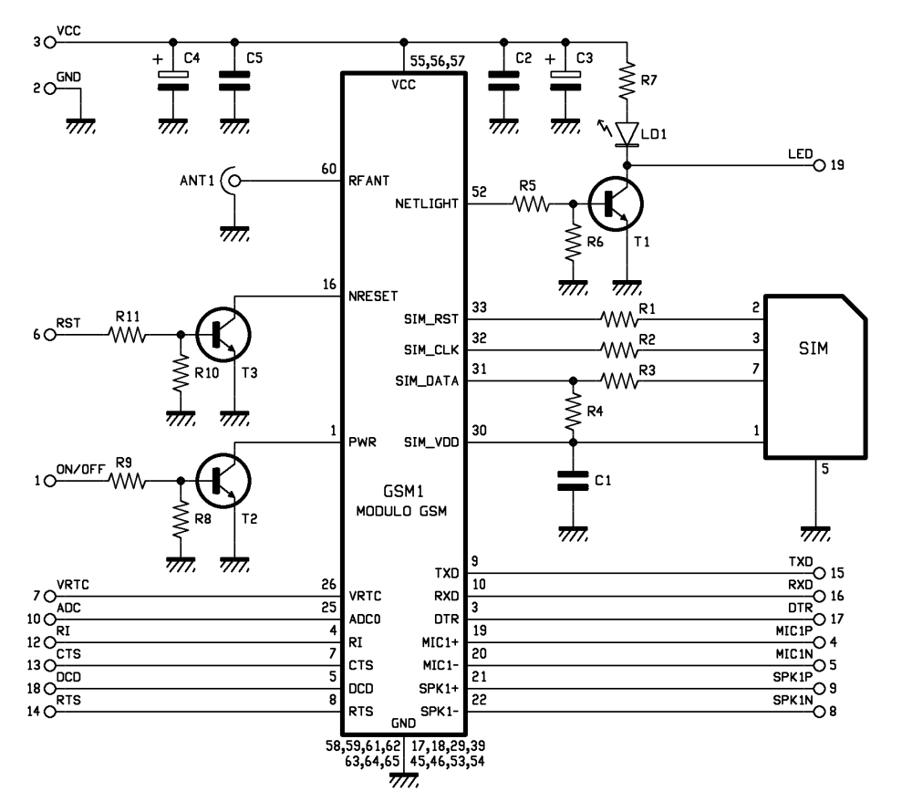
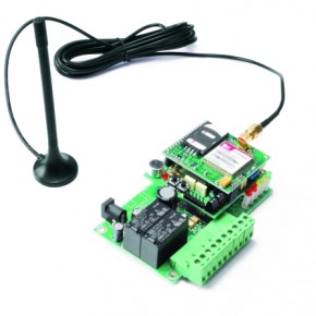
The printed board hosting the SIM900 is mounted above all. For this purpose, it has two pin-strips for connections with the remote control circuit: one made of 3-pins and another made of 16-pins: the first carries positive and negative digital power supply, as well as the PWR, while the second contains all the signals and the communication lines to and from the GSM module, and also the ground of the analog section of the mobiles (AGND, 11 contact pin).
Functions and commands
The device performs two functions:
1) warns with voice messages about the occurrence of a certain condition on one or both of its optically isolated inputs,
2) can controls remote actuators
Our system provides notification of alarm conditions also via SMS.
For configuration and remote control a large set of commands is provided to be sent via SMS. There is a second set of commands, that you can give via DTMF, but are limited to relays control, and reading the status of inputs.
SMS commands are of two types: those to define how the system is supposed to work (configuration) and those more operational, used to activate and deactivate each of the outputs, both impulsive (defining, within the specified limits, the activation time) or bistable, and to interrogate the unit to know the condition of one of the outputs.
DTMF commands
When you call the system, it answers with a voice menu providing the list of commands, each of them can be imparted by pressing a key on the keyboard.
As said, the menu and a few sentences about the password can not be changed, but you can freely edit the answers that the system dynamically provides. Since we have two inputs and two output we have eight messages.
You can basically map each permutation to a specific messge mixing inputs an ouputs.
The same applies to the inputs and outputs. For example, if the relay controls an electric lock that locks a door we can model “open lock” and “closed lock” conditions. Furthrmore, if we use a relay to control a siren we can play back messages such as “siren activated” or “siren off.”
To record the messages, you just need to press one of two buttons and then give power. By doing so you enter programming mode (5 flashes of the yellow LED signal). You can not record messages when the circuit is already in operation.
Upon entering the audio programming, after the button has been released the first message is played: by pressing P1 (NEXT) it moves to the next message and so on.
To record a new message instead, you have to press and hold P2 (REC): the LD1 LED lights up indicating the recording (the maximum time available to record a message is 5 seconds).
Configuration software
The program runs in a PC running Windows XP/2000/Vista/7 (you can even emulate).
You can use the very same program also for our TDG133, TDG134, TDG139, TDG140 telecontrols: just connect the USB to the device and the computer will automatically recognize it. Depending on the device connected, the software adapts its interface, showing the main dialog box, for the only relevant cards.
In the info tab we summarized the control characteristics (in this case, TDG135), the firmware version and SIM900 IMEI.
The Master Numbers section summarizes the numbers in the list (a maximum of 8) that are authorized to perform the configuration and issue commands via SMS or call.
With the Alarms tab, you can specify how the relative number shall be alerted, if by SMS or by a phone call.
Inputs tab allows you to check or change the logic of the inputs, the inhibition time between a an alarm and the next, and the observation time, ie the time interval for which the alarm condition must persist.
The Outputs tab allows you to set the relays operating mode from the dedicated section (Manual Control), you can manually activate the relay to verify the correct operation of the entire system. On the same tab there’s a Ripristino all’avvio section, from which we can decide if the telecontrol shall restore the state of the outputs after a black-out, or leave them all to rest.
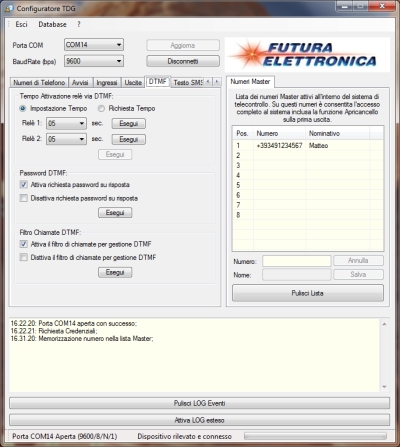
This brings us now to the tab that is perhaps the most important: the DTMF. From here we can set the activation intervals of output relays and decide whether the DTMF dialer must follow the commands unconditionally or only if the caller dials the password.
A third section of the DTMF tab is the one that allows you to enable or disable the filter on calls (DTMF Call Filter).

[…] GSM Voice Dialer with Automation Control – [Link] […]