.
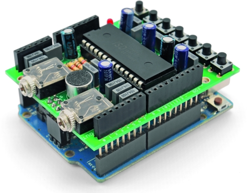
The objective of this project is to build an Arduino voice shield to empower thousands of voice related applications! All this mostly thanks to an integrated ISD1790PY chip.
This particular voice/TTS feature can be useful to integrate voice messages in alarm systems, to implement generic I/O controls in home automation or even in home security applications: something like playing an alert when a person or a vehicle approaches any given protected area. The use cases are many and limited only by your imagination!
You could even create your own Lucy Liu Bot :D
The Arduino integration is made simple thanks to a special library which is responsible for managing the ISD voice chip.
The Diagram
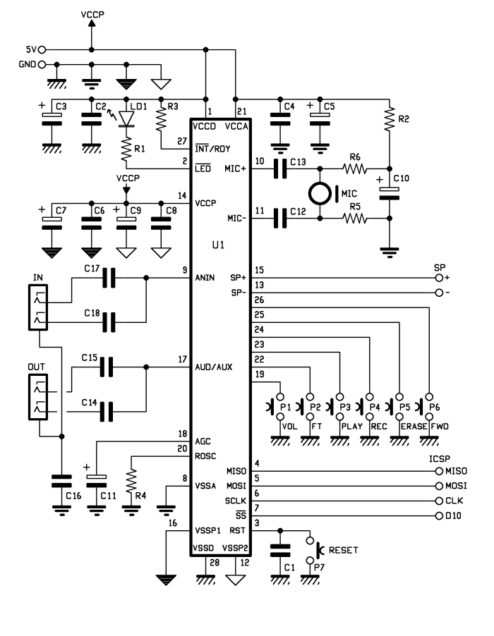
While this shield can operate stand-alone, it can be better managed through and SPI interface: by connecting this with Arduino it can take control of the speech synthesis.
The ISD1790PY sports a microphone input with automatic gain control (AGC), an output for 8 ohms speaker and another analog output that can be configured to drive an external amplifier. Volume control features as well as anti-aliasing and smoothing filter are provided and the vAlert (voiceAlert) function is used to indicate a new message is available in memory
ISD1790PY provides aso four sound effects to confirm operations such as start recording, stop recording, delete, forward and memory reset, along with vAlert, the effects are played from the AUD / AUX output.
The speaker output is amplified by a built-in power bridge stage, whose power is separated from those of both the analog section (microphone input with AGC, analog not amplified output) and digital section (sampler, memory) and is taken from the Vccp and Vssp1/Vssp2 pins.

Regarding the control buttons:
- P1 adjusts the listening volume during playback
- P2 lets you listen to the audio directly applied to ANIN
- PLAY and REC control respectively the playback and recording
- ERASE clears the memory
- FWD allows – if memory contains several messages – to jump from one to another (in this case, pressing P5 deletes only following messages: in other words, if we have recorded 5 messages and we press FWD to move to the third one, by pressing ERASE we’ll delete the memory area from that point until the beginning of the fourth message, which means the third track)
The same applies to PLAY and REC: both are valid for the memory slot where you are located at the time they are pressed.

While ISD1790PY allows both recording the entire memory or divide the space into partitions (each defined by a specific address), addressing can only be done by SPI by adding to the command to desired address. With manual control buttons you have to handle the P4 button: recording starts by pressing the button: it stops releasing it.
Imagine that memory is empty: pressing REC I can start recording, releasing it, recording stops and ISD1790PY adds a marker in the corresponding memory location. This marker will then be used when playing as EOM = End Of Message. When hitting the PLAY button, reading starts from the last EOM marker and stops at the next.
Message logging is carried out directly with a microphone capsule (MIC) connected to the appropriate U1’s differential input (MIC+ & MIC-) via the two decoupling capacitors (from bias network and by ground), polarized by the R2, R6, R5 network.
C10 capacitor filters out the capsule power to ensure registration is not disturbed by any noise propagated.
The IN audio line (that’s why a female stereo jack has been realized, whose L and R contacts end on the same U1 pin thanks to C17 and C18 capacitors) can be useful if you want to record from an external source.

Recording time is determined by the clock frequency of ISD1790PY internal oscillator, which marks the sampling; such sampling frequency is defined by the value of the R4 resistor, in this case is 8 kHz.
The entire shield takes the power supply from Arduino 5V and GND pins. The three power lines (analog, digital, power) are cross-linked to Arduino’s 5V, close to the filter capacitors.
Those capacitors are there to prevent oscillations caused by digital sampling (Vccd) or from the operation of the audio power amplifier (Vccp).
The three grounds (one for the analog section, one for the digital and one for the loudspeaker amplifier) are indicated with different symbols on the circuit diagram and joined after the filtration operated by capacitors C4 and C5 (analog), C2 and C3 (digital) and C6, C7, C8, C9 (power). Together they are joined to the pin that leads to the Arduino GND.

BOM
[code]
R1: 1 kohm
R2: 4,7 kohm
R3: 100 kohm
R4: 82 kohm
R5: 4,7 kohm
R6: 4,7 kohm
C1: 100 nF 63 VL
C2: 100 nF 63 VL
C3: 10 µF 100 VL
C4: 100 nF 63 VL
C5: 10 µF 100 VL
C6: 100 nF 63 VL
C7: 10 µF 100 VL
C8: 100 nF 63 VL
C9: 10 µF 100 VL
C10: 4,7 µF 100 VL
C11: 2,2 µF 63 VL
C12: 100 nF 63 VL
C13: 100 nF 63 VL
C14: 100 nF 63 VL
C15: 100 nF 63 VL
C16: 100 nF 63 VL
C17: 100 nF 63 VL
C18: 100 nF 63 VL
LD1: LED 3 mm red
U1: ISD1790PY
P1: Microswitch
P2: Microswitch
P3: Microswitch
P4: Microswitch
P5: Microswitch
P6: Microswitch
P7: Microswitch
MIC: Mic D10 mm
– Jack 3,5 mm CS (2 pz.)
[/code]
The sketch
To manage the shield functions see the sketch
#include <ISD1700.h>

ISD1700 chip(10); // Initialize chipcorder with
                  // SS at Arduino's digital pin 10

int apc=0;
int vol=0;  //volume 0=MAX, 7=min

int startAddr=0x10;
int endAddr  =0x2DF;
int inInt=0;
void setup()
{
  apc = apc | vol;  //D0, D1, D2

  //apc = apc | 0x8;    //D3  comment to disable output monitor during record

  apc = apc | 0x50;    // D4& D6  select MIC REC
  //apc = apc | 0x00;      // D4& D6  select AnaIn REC
  //apc = apc | 0x10;    // D4& D6  select MIC + AnaIn REC

  apc = apc | 0x80;    // D7   AUX ON, comment enable AUD

  apc = apc | 0x100;     // D8   SPK OFF, comment enable SPK

  //apc = apc | 0x200;   // D9   Analog OUT OFF, comment enable Analog OUT

  //apc = apc | 0x400;   // D10  vAlert OFF, comment enable vAlert

  apc = apc | 0x800;     // D11 EOM ON, comment disable EOM

  Serial.begin(9600);
  Serial.println("Sketch is starting up");
}

void loop()
{
  char c;

  if(Serial.available())
  {
    /* Power Up */
    chip.pu();
    c = Serial.read();
    switch(c)
    {
       case 'A':
         Serial.println(chip.rd_apc(), BIN);
         break;
       case 'Y':
         chip.play();
         break;
       case 'P':
         chip.stop();
         delay(500);
         break;
       case 'E':
         chip.erase();
         delay(500);
         break;
       case 'R':
         chip.rec();
         break;
       case 'F':
         chip.fwd();
         delay(500);
         break;
       case 'Z':
         chip.g_erase();
         delay(500);
         break;
       case 'I':
         Serial.println(chip.devid(), BIN);
         break;
       case 'W':
         Serial.println(apc, BIN);
         chip.wr_apc2(apc);  //
         break;
       case 'S':
         Serial.println(chip.rd_status(), BIN);
         break;
       case '>':
           startAddr=SerialIn();
           Serial.print("startAddr: ");
           Serial.println(startAddr);
         break;
       case '<':
         endAddr=SerialIn();
         Serial.print("endAddr: ");
         Serial.println(endAddr);
         break;
       case 'y':
         chip.set_play(startAddr,endAddr);
         break;
       case 'r':
         //chip.set_erase(startAddr,endAddr);
         //delay(500);
         chip.set_rec(startAddr,endAddr);
         break;
       case 'e':
         chip.set_erase(startAddr,endAddr);
         delay(500);
         break;

    }
    Serial.print("Status---> ");
    Serial.print(chip.CMD_ERR()? "CMD_ERR ": "OK ");
    Serial.print(chip.PU()? "PU ": "NO PU ");
    Serial.print(chip.RDY()? "RDY ": "Not_RDY ");
    Serial.print(chip.rd_status(), BIN);
    Serial.println();
    delay(1000);
  }
}

int SerialIn(){
  inInt=0;

           while (Serial.available() <= 0)
         {
           delay(300);
         }
           while (Serial.available()) {
            // get the new byte:
            char c = Serial.read();
            // add it to the inputString:
            inInt = (inInt*10) + (c-48);
            // if the incoming character is a newline, set a flag
            // so the main loop can do something about it:
            if (c == '\n') {
              //stringComplete = true;
              Serial.print("stringComplete ");
            }
          }
         //c = Serial.read()-48;
         //mess(c);

  return (inInt);

}
/*
void mess(int num){
  Serial.print("num: ");
  Serial.println(num);
  startAddr=(0x50*num)+0x10;
  endAddr=(startAddr+0x50)-1;
  Serial.print("startAddr: ");
  Serial.print(startAddr, HEX);
  Serial.print(" - endAddr: ");
  Serial.println(endAddr, HEX);

}
*/
Using The software

A simple application is made available, to be used when you need to control the recording and you want to do so with extreme precision. It’s also useful to load up music or voice messages from a personal computer: in this case it must be MP3 or WAV files.
Download the Voice shield software
Installation and Use
note: Microsoft .NET Framework 4 is required to install the software.
The use of the software is fairly intuitive: you need to first choose the COM port for Arduino. Choose Settings from the Tools menu you can then define the serial port and configure operating parameters, such as data-rate, parity, etc..
Once done, Save the settings and Exit the dialog box to return to the main window.
You must then define, through the the top left box, the type of integrated chip mounted in the shield: choose from the drop-down menu or press the Request button. Furthermore, you must define the oscillator operating frequency and, therefore, the maximum time available for recording: choose the value of the R_Osc mounted on the shield (default is 82 kohm) from the drop-down menu.
Once this is done, in the box immediately below the information, there is a box where you can select the ID of the track you want to record, import .mp3 or .wav files and possibly listen those before transferring.
By ticking the option box Automatically calculate memory locations … the program will determine the needed memory to create a storage that is consecutive to the previous track (or the first available location). Removing the mark you could define at will the position of the recording.
Repeat the procedure for each of the records: every time you add one, it will appear in the right panel.
The first buttons row – above the playlist panel – allows you to execute various actions.
During the playlist design phase, you can also set the playback volume. Buttons under the panel are related to the management of ISD chip (ISD Recording starts recording selected tracks).
The ISD Play button allows you to listen the content, shown in the white box. If you want to erase tracks, checkmark it and click Delete tracks from the ISD: this will remove the related tracks from the chip.
If you’re not in the mood of dealing with making the PCB and all: buy the Arduino Voice Shield kit on our Open Electronics Store and go for your voice related application!

“sketch is starting up” rofl
I’ve had an ISD1760 module kicking round ever since I purchased it but became despondent as I could not get it to work using SPI. Your post – especially the Special Library, was extremely useful to enable me to record audio via the AnaIn port and have this play on demand using SPI control from my Arduino.
OK, I didn’t make the shield but the sample sketch helped me understand how it fitted together.
OK, I could not get the Voice Shield s/w to run – it was all in Italian and fell over an exception on installation. Also the app seemed to be in Italian whereas the screen grabs of it were in English. Possibly an issue with my Local setting.
I liked the case ‘m’ option – this sets a starting memory block for recording / playback so even if you don’t know exactly how long your clip is (main function of windows app as I could make out), you can guess the length and chop the set_play endAddress accordingly. I’m not sure why it took me so long to find your post – I may re-post it on the Arduino forum.
OK, I’m 10 years late but better late than never.
Thanks for bringing this all together.