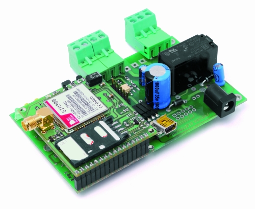
For the GSM temperature controller we have provided a double-sided PCB with plated holes, made by photoengraving; once you have the board you can start the assembly with SMD components.
The thermal probe can also be mounted out of the PCB, connecting it somewhere else by means of a three-conductor cable, at least 20 meters long.

Top Layer

Bottom Layer
PARTS LIST:
R1: 0,1 ohm 1W (1206)
R2, R21: 2,2 kohm (0805)
R3: 1,2 kohm (0805)
R5, R6, R9, R18, R19: 4,7 kohm (0805)
R7, R8, R13, R17: 330 ohm (0805)
R10: 10 kohm (0805)
R15, R16: 1,5 kohm (0805)
R20: 1 kohm (0805)
R11, R12, R14, R22, R23, R24, R25, R26. R27: unused
R28, R29: 0 ohm
C1, C4, C7: 100 nF multilayer (0805)
C2: 1000 µF 35 VL electrolytic
C3: 100 pF ceramic (0805)
C5: 100 µF 16 VL electrolytic
C8: 470 µF 6,3 VL tantalum (CASE-D)
C11: 100 µF 16 VL electrolytic
C13: 100 nF multilayer (0805)
C8, C14, C15, C16: 470 µF 6,3 VL tantalum (CASE-D)
C6, C9, C10, C12, C17, C18, C19, C20: unused
Q1, Q2: unused
U1: MC34063AD
U2: DS18B20
U3: 24FC256-SN
U5: TLP181
U6: PIC18F46K20-I/PT (MF857)
U4, U7: unsued
D1, D3: 1N4007
D2: 1N5819
D4: unused
T1: BC817
T2: unused
LD1: LED 3 mm red
LD2: unused
LD3, LD4: LED 3 mm yellow
LD5: LED 3 mm green
L1: Coil 20 µH
RL1: Relay 5V single pole
RL2: unused
P1: Microswitch
F1: Slow fuse 2 A (1206)
Miscellaneous:
– 2 pole terminal block (2 pcs.)
– 3 pole terminal block
– power plug
– 6 pin male strip
– 3 pin female strip
– 16 pin female strip
– 4 pin 90° female strip
– PCB
Download PCB details (Layout and Gerber): PCB
