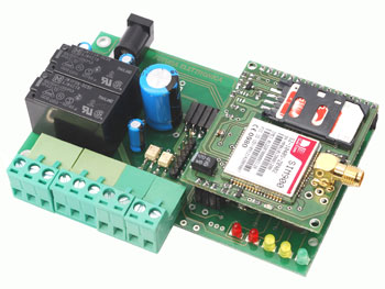
Now that we are familiar with the structure and functions of the base circuit, we can look at how it is built; let us state in advance that its realization presupposes a double-layer printed board with metallic holes, a choice we made in order to be able to reduce the overall size of the device. As a result, you need to have a 20÷25W solder with a very fine point, as well as thin alloy thread (max. 0.20 inches in diameter). As for the printed circuit, you can find the traces corresponding to the end of this post; if you should be unable to create it on your own, keep in mind that there are various companies that can do it for you at a fairly low cost.


Layout MotherBoard Remote Control
PARTS LIST:
R1: 0,1 ohm 1W (1206)
R2: 2,2 kohm (0805)
R3: 1 kohm (0805)
R4: 100 kohm (0805)
R5, R6, R11, R18, R19, R22: 4,7 kohm (0805)
R7, R8: 330 ohm (0805)
R9: 4,7 kohm (0805)
R10, R12: 10 kohm (0805)
R11: 4,7 kohm (0805)
R13, R14, R17: 330 ohm (0805)
R15, R16: 1,5 kohm (0805)
R20: 1 kohm (0805)
R21: 2,2 kohm (0805)
R23: 330 kohm (0805)
R24: 39 kohm (0805)
R25: 56 kohm (0805)
R26, R27: 100 kohm (0805)
C1, C4, C6, C7, C13, C18, C20: 100 nF multilayer (0805)
C2: 1000 µF 25 VL electrolytic
C3: 100 pF ceramic (0805)
C5, C11, C12: 100 µF 16 VL electrolytic
C8, C14, C15, C16: 470 µF 6,3 VL tantalum (CASE-D)
C9, C10: unused
C17, C19: 10 pF ceramic (0805)
Q1: unused
Q2: Crystal 3,579545 MHz (HC49/4H SMX)
U1: MC34063AD
U2: DS18B20+
U3: 24FC256-SN
U4, U5: TLP181
U6: PIC18F46K20-I/PT (MF857)
U7: MT88L70AS
D1, D3, D4: 1N4007
D2: 1N5819
T1, T2: BC817
LD1, LD2: LED 3 mm red
LD3, LD4: LED 3 mm yellow
LD5: LED 3 mm green
L1: Inductor coil 20 µH
RL1, RL2: Relay 5V single pole
P1: Microswitch
F1: Slow fuse 2 A (1206)
Miscellaneous:
– Screw connector 2 poles (2 pz.)
– Screw connector 3 poles (2 pz.)
– DC plug
– Male strip 6 poles
– Female strip 3 poles
– Female strip 16 poles
– Female strip 4 poles 90°
– PCB
Download PCB details (Layout and Gerber): PCB

And code file?