[youtube id=”XpYjn9-xgvY” width=”620″ height=”360″]
We have already seen many motorized versions of “human traction” transport means: bicycles and scooters, for example, or even some skateboard, but surely we lacked the motorized skateboard controlled by a smartphone.
Well, now we have found it!
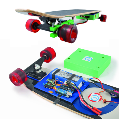
It is a dedicated project, which combines the motorized version of the popular wheelboard with the most modern Android App technology that allows you to control the vehicle via Bluetooth, giving commands to start, stop and speed variation. A nice application, easily achievable, whose mechanical uses 3D printed parts by 3Drag printer for the traction mechanism. The control electronics is based on Arduino.
The base of this project is a traditional skateboard, the bottom of which the control electronics and the belt transmission, acting on a single wheel, are fixed to.
The electronics are three: Arduino in version A, an ESC to control the traction brushless motor used (develops a peak power of 1,190 watts) and a Bluetooth transceiver through which Arduino establishes the connection required to receive commands from the smartphone.
Arduino, through a proper sketch, interfaces with the smartphone, used here as a simple wireless remote control that allows you to move the skateboard at will of the user; according to the commands received, it generates the PPM signal to command the ESC, which in turn generates the three-phase voltage with which feeds the stator windings of the brushless motor.
The ESC module is an electronic circuit that generates a three-phase voltage that drives the windings of the brushless motors used, for example, in radio-models; these motors have the stator with three delta-connected windings and a rotor with magnets and pole pieces (at least three, spaced from each other by 120° or a multiple of 3 poles; the angular distance is equal to 360 ° divided by the number of polar expansions). The stator is driven by three square wave voltages whose pulse width depends on how much power is required to the engine: the more power is requested, the greater the pulses duration (=width) is, and vice versa. The frequency determines, instead, the rotor rotational speed.
Well, the ESC manages the parameters according to the PPM signal applied to its control input (being a radio-model ESC , it has a connector with three wires from which it receives the control pulses and through which supplies the 5 V to Arduino). The module also has the power cables to connect the battery, which in this application is a 4s LiPo (4-cell, 14.8V) 5,000 mAh capacity and discharge current equal to 25C (it can bear a125A peak current, which corresponds to 1500W on a 12V engine, theoretical). With the 5 Ah battery, you can skateboarding for about 30 minutes at maximum speed.
The connection scheme ESC – Arduino – Bluetooth is shown in Figure.

Bluetooth module
For the wireless connection, a dedicated module is used, dubbed HC05 and based on the Bluetooth chip BC417143 by CSR; it is a low cost transceiver unit (transmit / receive) sold from $ 5. To obtain the minimum possible size, the module has a contact pitch of just 1.9 mm, so to make its assembly easier we recommend getting an adapter to bear 2.54 mm pin-strip connections.
The module exists in various versions. In the project, the module is set with the default parameters regarding serial communication (9600, N, 8, 1) and Password / pairing code (1234). The module supports AT commands for setting the baud rate, the device name, passkey, the master / slave mode, etc.
The module technical features are:
– Baud-rate = 2400 ÷ 1,382,400 bps
– Compliance Bluetooth v2.0 + EDR
– Operating frequency of 2.4GHz (ISM band)
– Modulation: GFSK (Gaussian Frequency Shift Keying)
– Transmission power = ≤4dBm (Bluetooth Class 2)
– Sensitivity = ≤84dBm (with BER of 0.1%)
– Communication speed = 2,1Mbps / 160 kbps (asynchronous) and 1Mbps / 1Mbps (synchronous)
– Security authentication and encryption
– Power +3,3Vcc – 50mA
– Operating temperature = 20 ÷ 75 ° C
– Size = 26,9x13x2,2 mm
The brushless motor used for hauling is a Turnigy SK3 Aerodrive – 4250-350kv powered by a voltages ranging from 14 to 19V, which runs at 350 rpm / volt; it can absorb up to 53A and provide a maximum power of 1.190W. The motor shaft diameter is 5 mm and the weight is 266 grams. Upon it, it shall be applied a pulley fixed with a grain (or even with a hub and a self-centring chuck) to transmit torque to the skateboard wheel. The propulsion group properly made allows the skateboard to reach a maximum speed of 25 km / h, carrying a person between 60 to 70 kg.

Bluetooth module connection to Arduino
Our Bluetooth module operates at a voltage of 3.3V, then we will use the 5V and GND Arduino pins to feed it (they connect respectively to 5V and GND of HC05), while we will make a voltage divider to lower the module RX voltage since the HC05 RX tolerates only 3.3 V and not the 5 V TTL levels provided by the TXD Arduino pin.
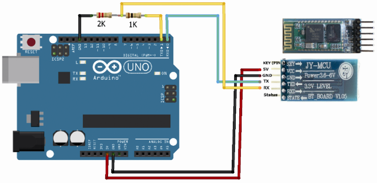
We can make the voltage divider by using a 2 KOhm and a 1KOhm resistors connected respectively between the Bluetooth module RX pin and Arduino GND and between Arduino TX pin and Bluetooth module RX pin. As for the Bluetooth module TX, we can directly connect it to Arduino RX, as it is also compatible with the 0 / 3.3V levels and so it will interpret 3.3V as a high logic state. About the sketch to upload to Arduino to receive data sent by our smartphone through the Bluetooth module, it will be written by creating a serial channel listening from the Bluetooth itself. The instructions are listed on code listing 1.
Listing 1
#include <Servo.h>
Servo esc;
int value = 0;
void setup()
{
// ESC is connected to Arduino PIN 9
esc.attach(9);
// init bluetooth serial connection
Serial.begin(9600);
}
void loop()
{
// Every cycle we read if a new data is on serial
// if no data is read, we get a 0 that we will drop
value = Serial.parseInt();
if (value != 0) {
// if Value is not 0, we will pass it to ESC
//The smartphone app will take care of sending a proper value
// (0179) to  bluetooth
esc.write(value);
}
}
ESC Module
Controlling a ESC (Electronic Speed Control) circuit with Arduino is never a simple thing, and it’s not about the software that you need to write but mainly because of the fine tuning needed to calibrate the ESC. Calibration is really important because otherwise the ESC would not understand what are the transmitter limits (we are referring to Arduino now, even if the typical use is on radio-models) and can not precisely control the engine.
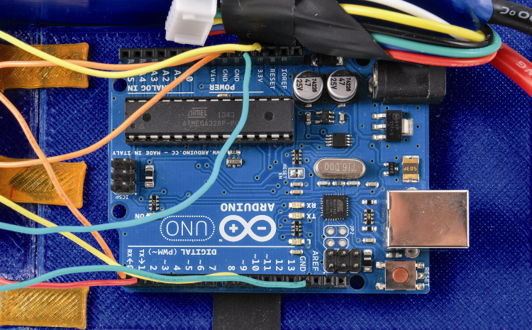
Let’s first see how we put our ESC within the circuitry managing the skateboard motor (Fig. 3): the ESC circuit connects the battery to the engine, and we use the BEC (a block which excludes the engine power supply if the battery is low, but still supplying 5 V to the control circuit, which in this case is Arduino) of the circuit to power Arduino. To do this, simply connect the red and black wires to 5V and GND Arduino connectors.
Finally we connect Arduino pin 9 to BEC orange connector, through which we will send the signal to the ESC.
Since the ESC is designed to receive inputs from a remote control receiver, with a PPM signal compatible with that normally sent to actuators, we can control it as if it was an actuator itself: for this reason, we do not have to write any code but we control it using the Arduino Servo available libraries. So we just include the libraries in our Servo sketch and we are done.
Smartphone control
The remote control unit of the skateboarding engine is done through an Android App called C’monStick, which runs on smartphones with that operating system; once installed and launched, it shows the screen shown in figure. To set speed, drag the cursor with your finger on the screen. For the rest, you can drive the skateboard as a normal non-motorized one, steering by leaning aside and pressing the board with your feet.
App is available for download

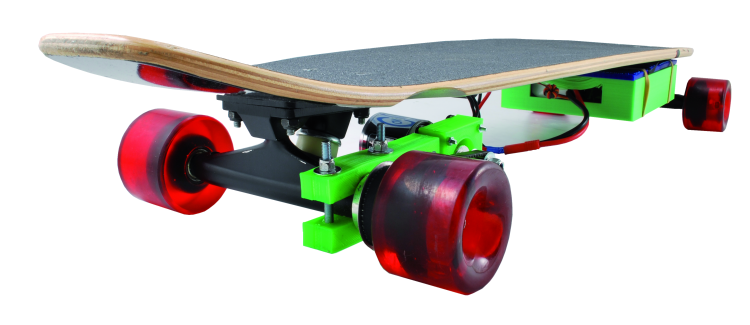
The Assembly
To install the motor on the skateboard you need a pulley of 1 cm less than the wheel diameter, to be screwed laterally (radially) to the wheel itself, making sure that the screws go straight and do not exit from the “tread”. This pulley may be obtained from a 3D printing in ABS from a template provided on www.thingiverse.com possibly processed with OpenSCAD, but you can also purchase it ready-to-use, in aluminum.
In any case it must contain a number of radial holes to fix it to the drive wheel. The PLA box that contains battery and electronics was made using a 3DRag printer. The same applies to the motor support, its 3D print has been developed after many field tests. The support we provided should be screwed in under the skateboard, exactly on the rear axle near the traction wheel; the support bracket has a clamp to be tightened by screws. On it, the engine is fixed with screws; the motor shaft is applied to a hub screw or to a chuck that is equipped with toothed pulley, ideal for the belt. You can also use a flat belt pulley, but in this case you have to increase its tension to prevent slippage. The belt teeth must have dimensions compatible with that of the hub and the toothed pulley applied to the wheel.

The propulsion unit fixing is designed for a certain model of skateboarding but do not necessarily apply to all; however, as we provide the STL file, each can customize it to print a version that suits your needs. It should also be said that you can even use other fastening systems such as a square piece of aluminum properly drilled. Fixed the mechanics, you have to think to electronics, housed in the box that is secured to the table bottom (for fixing you can use different solutions, ranging from clip, screws, and also to the simple silicone sealant.

From Store
Breakout RN-42 Bluetooth module

[…] web es http://www.cmonboard.com, y en Open-Electronics.com tenéis lo necesario para montaros uno, ¿os atrevéis? y si lo hacéis mandarnos el […]
Is it possible to hook up two esc on the arduino? In the case of two motors electric skateboard.
There are some project on line
http://www.instructables.com/id/ESC-Programming-on-Arduino-Hobbyking-ESC/?ALLSTEPS
How about using a $6 Bluetooth controller like this instead of the Smartphone?
http://www.banggood.com/Cobirey-VR-PARK-01-Wireless-Bluetooth-Controler-RC-VR-Gamepad-For-Android-iOS-p-1038101.html
[…] le projet est un peu plus détaillé, on utilise un smartphone pour communiquer en Bluetooth avec le skate1 au travers d’une […]
The download link for the app is not working. How can I get the app please ? :)