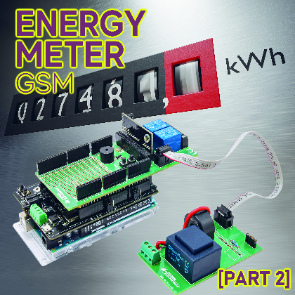
It monitors the electricity consumption and sends the detected data to the cloud through the GSM cellular network; it is based on an Arduino Mega equipped with GSM Shield and a board on which the measurement board is mounted. Second and final instalment.
In the previous post on Open Electronics, we have proposed the realization of a project created to monitor electricity consumption through a board for detection of voltage and current in the plant, entirely managed by an Arduino Mega 2560 board equipped with a GSM Shield, which implements the data connection on mobile radio network aimed at sending to a remote server of the detected data.
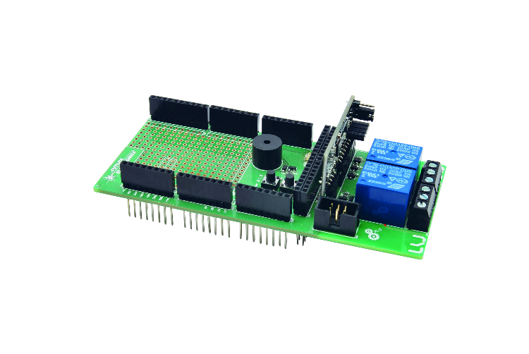
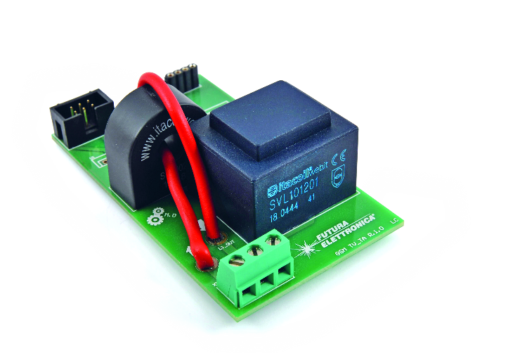
Physically, the project is composed of a sensor board that mounts the classic current transformers (TA) and voltage transformers (TV) on, which can take place in a particular female strip; the module Energy Meter FT1346M is equipped with a 2.54 mm pin pitch, as well as a shield made to be applied to Arduino Mega 2560 or Fishino Mega board; in addition, there is a GSM Shield for mobile data connectivity.
The project offers two possibilities of use: the configuration just described is the one for the application proposed in this article, i.e., the hardware managed by Arduino/Fishino Mega, and provides that the board with TA and TV transformers is a simple sensor of the parameters of the electrical power and is interfaced through the appropriate connector and its flat-cable to the GSM Energy Meter shield. This configuration allows the Arduino/Fishino Mega to acquire and process absorption data and the eventual sending via GSM/GPRS network.
But it is also possible to use the TA-TV board alone in combination with a Personal Computer. Still, the FT1346M module must be plugged into its female strip and not into the Energy Meter shield as in the complete configuration with Arduino.
The heart of the measurement is the FT1346M module, which needs the board with the TA and TV transformers. Still, it detects the corresponding voltages and determines phase, power factor, instantaneous absorption, apparent power, active and reactive, simply by analyzing the relationship between the waveforms provided by the two transformers. It is then the FT1346M that communicates the data to the computer through the interface connector.
The FT1346M is based on the MCP39F511 integrated circuit, which uses a sampling algorithm that takes a finite number of samples per cycle of the mains AC. The accumulation interval of the samples is given by the integer value 2N, which identifies the number of line cycles on which you want to sample and consequently perform calculations. For example, with N fixed at five, you have that the line cycles on which you will perform sampling and computation will be 32.
Well, after this summary of the project and a brush up on the operation of the integrated circuit that measures the power parameters, let’s pick up the conversation from where we left off in the first episode (in which we explained the hardware and the library for Arduino) that is the sketch that has been prepared to use the project in its full version, that is with the Energy Meter shield.
Sketch Test_MCP39F511
The sketch, written to work on the Arduino Mega 2560 or Fishino Mega boards, is proposed as a first approach to using the new MCP39F511 management library. This is divided into six separate files that we will comment on below:
- “Test_MCP39F511“. ® The main file containing variable declarations used in the sketch, string constants, and the two usual functions of Arduino projects: void Setup() and void Loop();
- “DigitalInput® Management file of the input I/O, that is the two buttons P1 and P2 present on the demo board GSM EnergyMeter R.1.1;
- “DigitalOutput® Management file of the output I/O or the two relays K1 and K2, the buzzer and the service LEDs LD1 ÷ LD4 always present on the demo board GSM EnergyMeter R.1.1;
- “Measures® Management file for reading electrical measures and visualization on serial monitor, if enabled;
- “TimersInt® File of management of the interrupt of system TIMER 5 containing the code of control of the temporal variables used in the sketch. TIMER 5 acts as a time base with 2 ms resolution;
- “Uart_to_Uart“. ® Management file for the serial communication between the Arduino Mega 2560 board and the EnergyMeter software installed on the PC. In practice, the data packets sent by the software, since it is not directly connected to the integrated into hardware mode, are intercepted and sent to the MCP39F511 integrated. As a result, responses from the integrated are intercepted and sent to the PC software.
Let’s analyze the main file “Test_MCP39F511,” where at the top we find a series of constants declarations, including the I/O to which are connected both buttons and relays, as well as LEDs and buzzer. These I/O are only available on the Arduino Mega 2560 boards. This is followed by a series of constants for managing the state machines used in the sketch and output I/O management.
We have then defined a constant threshold beyond which the system goes into alarm (500 W, modifiable by pressing the button P1, which we will discuss later) and an offset constant that, combined with the previous one, puts the system in pre-alarm.
This is followed by string constants to be used for printing on the serial monitor some information and the electrical measurements taken. Finally, we have the declarations of the state machines used and the variables needed for the sketch to work.
To better understand the firmware, we can help ourselves with the flowchart shown in Fig. 1, which highlights both the “void setup()” section of the sketch and the “void loop()” function of the sketch.

Fig. 1
The setup function used to configure the sketch includes the configuration of the TIMER 5 used to manage time variables, the configuration of input I/O (buttons), the configuration of output I/O (relays and buzzer), and the configuration of the UART of the serial monitor and the connection to the MCP39F511. The library interrupts are then enabled, the library I/O pins are configured, and finally, the reset condition of the MCP39F511 is released. Last but not least, the state machines used in the sketch are configured, some variables are configured, and the revision number of the sketch in use is printed on the serial monitor.
Once initialization is complete, the system enters the “void loop()” function where the following functions are executed (see the second section of the flow-chart):
- debouncing the two buttons P1 and P2;
- state machine management for the functions associated with the two buttons P1 and P2;
- state machine management for reading electrical measurements;
- state machine management for Uart-To-Uart function; this function requires running the software on EnergyMeter PC R.1.0.4.0 or higher;
Suppose the intervention thresholds are not being set using button P1. In that case, the function of monitoring the active power engaged concerning a preset intervention threshold is carried out to warn using an acoustic-visual signal when the power threshold is exceeded. The system only warns of the overrun and does not act on the two relays on the board, which can be energized or de-energized by pressing the buttons P1 and P2. If a threshold configuration is in progress by pressing button P1, this function is ignored until initialization is complete.
If the EnergyMeter software is running, it can take advantage of the UART of the Arduino IDE’s serial monitor to communicate with the MCP39F511 IC. In other words, the UART of the serial monitor acts as a bridge between the software and the integrated. In this way, you can configure the registers of the integrated unit or read the electrical measurements directly and display them on the PC monitor. This functionality has been named Uart-To-Uart. If it is not active, the flowchart continues with the following available functions. Otherwise, it returns to the head, repeating the above functions.
The system, every two seconds, begins a session of reading the registers containing the electrical measurements. In other words, it activates the read state machine seen in the previous points.
If you are not running a readout session, the electrical measurements are printed on-screen on the serial monitor every ten seconds.
The P2 button can activate the Microchip factory parameter reset function. To do this, press the P2 button for at least 6 seconds and then release it. The yellow LED LD2 will indicate this selection. In this case, the system will send a text string with a specific code to the MCP39F511 so that it can start its internal procedure to reset the parameters. If you want to reset the FT1346M to factory settings, press P2 for more than 3 seconds but less than 4 seconds. The red LED LD1 will indicate this selection. In this case, the EEPROM of the MCP39F511 is read to retrieve the recovery data and send them to the integrated circuit.
BUTTONS MANAGEMENT
This concludes the description of the main loop. Let’s then consider the management of the P1 and P2 buttons.
If pressed for a period of less than 1 second, pushbutton P1 energizes/de-energizes the corresponding relay K1; the same applies to pushbutton P2, but it refers to relay K2.
Button P1 is associated with the function of setting the intervention threshold. The default value loaded at power-up is always 500 W, with an offset of 100 W.
This means that if 500 watts are exceeded, the system goes into alarm (red LED LD1 ON; the buzzer emits an acoustic signal to warn that the threshold has been exceeded), but if it remains below 400 W, the system is in normal conditions (green LED LD3 on). Between 400 W and 500 W is pre-alarm (yellow LED LD2 lit).
Changing the threshold value changes the trigger point, while the offset remains unchanged.
So the thresholds that can be set by button P1 are as described below.
- Prolonged pressure for at least 1 second. LED LD1 comes on to indicate the selection of 1 kW. If you release button P1, the buzzer emits one beep to confirm the selection.
- Press and hold for at least 2 seconds. LED LD2 illuminates to indicate the selection of 2 kW. If you release button P1, the buzzer emits two beeps to confirm the selection.
- Press and hold for at least 3 seconds. LED LD3 illuminates to indicate the selection of 3kW. If you release button P1, the buzzer emits three beeps to confirm that the threshold has been selected.
- Press and hold for at least 4 seconds. LD1 and LD2 LEDs illuminate to indicate the selection of 4 kW. If you release button P1, the buzzer emits four beeps to confirm the selection.
- Press and hold for at least 5 seconds. LEDs LD1 and LD3 light up to indicate the selection of 5 kW; if you release button P1, the buzzer emits five beeps to confirm the selection.
- Prolonged pressure for at least 6 seconds. LD2 and LD3 LEDs illuminate to indicate the selection of 6 kW. If you release button P1, the buzzer emits six beeps to confirm the selection.
Now let’s move on to the P2 button; this is used to energize/de-energize relay K2 if pressed for less than one second. Otherwise, it is used to restore the factory parameters. In particular, if the P2 button is pressed for at least 3 seconds, the factory parameters of the FT1346M measurement board are restored.
The LD1 LED lights up to indicate the FT1346M factory parameter reset selection. When the button is released, the procedure is started. In addition, a string is printed on the serial monitor to indicate what has been done.
On the other hand, if the P2 button is pressed for at least 6 seconds, the Microchip factory parameters are restored by sending the appropriate serial command. The LD2 led lights up to indicate this selection; when the button is released, the procedure is started, and the string denoting the successful restoration operation is printed on the serial monitor.
As for the electrical measurements handled by the sketch, we have the following:
- RMS voltage (library function called cmd.MCP39F511_ReadRmsVoltageRaw();)
- Current RMS (library function called cmd.MCP39F511_ReadRmsCurrentRaw();)
- Network frequency (library function called cmd.MCP39F511_ReadLineFrequencyRaw();)
- Power factor (library function called cmd.MCP39F511_ReadPowerFactorRaw();)
- Apparent power (library function called cmd.MCP39F511_ReadApparentPowerRaw();)
- Active power (library function called cmd.MCP39F511_ReadActivePowerRaw();)
- Reactive power (library function called cmd.MCP39F511_ReadReactivePowerRaw();)
As for the power factor, you must also call the Cmd.CalcPowerFactor() function calculates the correct value since the data read is in two’s complement. When the electrical measurement is printed on the serial monitor, it is adjusted according to the decimal places assigned to the various measurements. For example, for RMS voltage measurement, we have:
Serial.println((float)(Cmd.VoltageRmsRaw.uWord/(pow(10, VOLTAGE_DEC))));
Then the read value of the RMS voltage, saved in the appropriate library data structure, is divided by a power of 10 and so on for all other measurements.
Let’s make one last consideration: at the top of the file “Test_MCP39F511“, there is a directive to the compiler named “ONLY_SOFTWARE_ENERGY_METER.” This is usually commented out and therefore disabled. When you remove the comment and recompile the sketch, you will have that the only active function in the “void loop()” will be the “Uart-to-Uart” function for the configuration of the measurement board using EnergyMeter software R.1.0.4.0 or higher.
PC SOFTWARE
EnergyMeter R.1.0.4.0:
Let’s conclude with some brief comments on the new version of the software EnergyMeter R.1.0.4.0, which provides a series of commands for managing the EEPROM memory of MCP39F511.
Fig. 2 shows the new interface of the software, where we have highlighted in red the new commands created that we are going to describe:
- Write Calibration Registers and Freeze FT1346 Eeprom Factory Data“. this command sends the data to the calibration registers of the MCP39F511 and, at the same time, saves the data in EEPROM in the appropriate memory locations;
- Write Design Configuration Registers And Freeze FT1346 Eeprom Factory Data“. this command sends the data to the configuration registers of MCP39F511 and, at the same time, saves the data in EEPROM in the proper memory locations;
- View MCP39F511 Eeprom” . with this command, the management window of the EEPROM memory of the MCP39F511 is called.
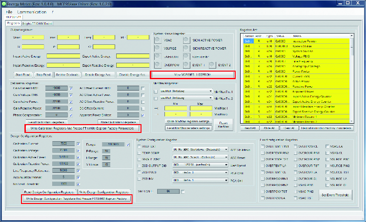
Fig. 2
Fig. 3 highlights the EEPROM memory management window; the table shows the data eventually stored in the memory. As already widely said, this is divided into pages. Each page is composed of 8 Word for a total of 16 bytes.
On the left side of the user interface, we find the commands to read or write data from a file on the computer; this is useful when you have to take data from an EEPROM and then write them into the memory of another FT1346M measuring board, or when you have to program a series of measuring boards.
So, to summarize:
- “Save MCP39F511 Eeprom Data File“. saves in a file the data eventually read from the EEPROM memory;
- “Read MCP39F511 Eeprom Data File“. reads data from a previously saved file;
- “Reset Table Values® resets the data displayed in the table back to the default values or 0xFFFF.
On the right of the user interface screen, instead, we find the commands to read, write or erase the EEPROM memory of the MCP39F511 integrated circuit mounted on the FT1346M measurement board. Specifically, we have:
- “Reads All Eeprom Pages from the MCP39F511“. reads all EEPROM memory pages from the MCP39F511 and displays their content in the table;
- “Writes All Eeprom Pages of the MCP39F511“. writes all the EEPROM memory pages of the MCP39F511, taking their values from the table;
- “MCP39F511 Bulk Erase EEPROM“. executes the total erasing of the EEPROM memory bringing it back to the default value that is 0xFFFF;
- “Reads a single EEPROM page from the MCP39F511“. Reads a single page of EEPROM memory and shows its content in the table. On the left is the text box in which to enter the memory page you want to read;
- “Writes a single EEPROM page of the MCP39F511“. Writes a single EEPROM memory page of the MCP39F511; data are taken from the corresponding memory page shown in the table.

Fig. 3
Last but not least, we have the configuration window of the settable thresholds of the MCP39F511 integrated circuit. 4 shows the new window with the latest available command (in the software release we are describing) highlighted in red, which allows us to write the threshold values in the appropriate registers and to save them in the EEPROM memory.

Fig. 4
CONCLUSIONS
With this, we can say that we have concluded the discussion of the Arduino library for managing the MCP39F511 integrated circuit in all its forms and a thorough manner. Thanks to this piece, we can now move on to integrating the same in a data management system with our GSM board or any other electronic board for interfacing to a database for the management and display of electrical measurements acquired. We will be developing an application of the system with other hardware in the future, so follow along.
FROM OPENSTORE
VOLTAGE MEASUREMENT TRANSFORMER
CURRENT MEASUREMENT TRANSFORMER
