Just few weeks ago, the maker Electronoobs announced the Homemade Soldering Iron v1.0, but unfortunately it encountered many problems from the beginning: the design was held back by the quality of the $5 replacement soldering iron tips he designed it around.
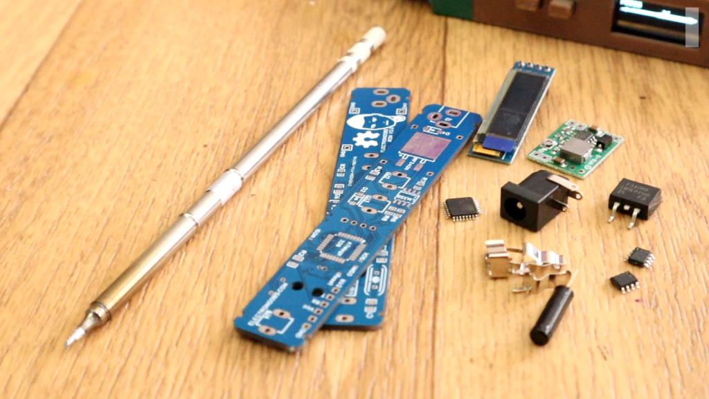
Now Electronoobs is back with the second version of the Soldering Iron and this time it’s using the vastly superior HAKKO T12 style tip. As this tip has the thermocouple and heating element in series it involved a fairly extensive redesign of the entire project, but in the end it’s worth it.
The new iron replaces the old MAX6675 with a LM358 operational amplifier to read the thermocouple in the T12 tip. Electronoobs then used an external thermocouple to compare the LM358’s output to the actual temperature at the tip. Using Arduino code, with this data he created a function which will return tip temperature from the analog voltage.
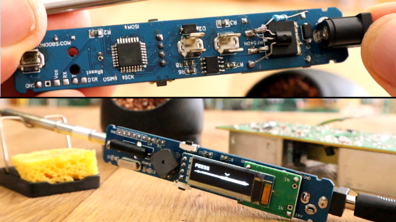
First, let’s see what improvements we have for this new board. First, the Iron tip is not that big and ugly one anymore. Now we use the T12 tip. For taht the board has 3 PCB clips to fit the tip in place. The first clip is connected to nothing. But the two clips in the midle are positive and negative connections of the iron tip. Those connections are the thermocouple and heating elenent in series. To read then temperature, we now use and OPAMP configuration and amplify the voltage drop across the iron tip connectors and then read the temperature corresponding to that drop.
We now have side 90 degrees push buttons and that will give us more space on the board and the buttons are now easier to push. The board alos has a buzzer for sound signals such as entering sleep mode. A very interesting component is the vibration sensor which is just a tube with metal connectors inside. We will use this to get out of sleep mode when movement is detected. The board is still using the ATMega328p-AU chip at 16MHz and the same buck converter for 5V from main input of up to 24V. Same DC connector, same MOSFET and same other small components.
Please, watch the video below for further information.
