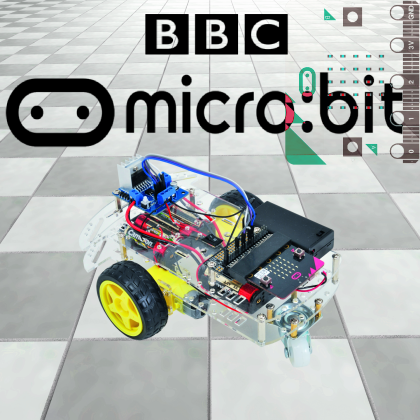
It is a newborn board, but it is rapidly growing in popularity thanks to the potential we are going to show you through the project of a robot on wheel that can be controlled by a smartphone via Bluetooth.
micro:bit is a small but solid and powerful prototyping board designed by no other than BBC (the English broadcaster), that can be easily programmed from a personal computer; besides the microcontroller which represents its core, it has onboard sensors such as accelerometer, compass and a small “display” composed of a 5 x 5 LED matrix. The small board has built-in 2.4 GHz wireless Bluetooth LE connectivity, implemented thanks to a dedicated transceiver and a proprietary protocol, besides an antenna integrated into the PCB. By combining the ease of use of micro:bit and a motor controller, in this article we are going to show you how to create a robot on wheels that can be controlled through an application from your smartphone using the onboard low-energy Bluetooth link. For a start, we must mention the origins and structure of micro:bit. The micro:bit project micro:bit (http://microbit.org/) is the mind child of BBC, promoter and coordinator (with the nonprofit goal to provide kids and students with a platform to easily learn the basics of programming…), and it is also supported by several partner companies, each providing a portion of the onboard components; among these companies we can find ARM (providing the processor and owner of the known architecture), Freescale (providing the sensors), Nordic Semiconductor (providing the transceiver and Bluetooth controller), Samsung and others.
The onboard sensors allow developing various applications, such as IoT and wearable electronics applications. The sensors are connected to the main controller through the I²C bus connected on the P19 (SCL and P20 (SDA) pins on the GPIO comb connector (with direct insertion).
The magnetometer can generate an interrupt towards the main processor while the accelerometer can generate two different interrupts towards the main processor. The latter, a nRF51, also includes a temperature sensor.
The project
Very well, after this brief introduction on the micro:bit board we can get down to business, i.e. describing the robot on wheels project.
The electronics of our robot is composed of a micro:bit board nested in the connector of a docking station board, which will allow to create electric connections with the rest of the hardware, composed of the controller based on the integrated L298N driver by ST and the motoreducers piloted by it.
In terms of structure for our robot, we chose the frame kit sold by Open Electronics with product code 2846-FISHGOCHASSIS, including a robotic platform composed of a Plexiglas body formed by two plates, two motoreducers, two Tamiya racing wheels, a metal ball-caster, a deviator, a power outlet, a 4xAA battery compartment with screws, nuts and hex bolts to assembly the two plates.
As for the programming, since we are dealing with the micro:bit, we will choose its dedicated language and development environment, i.e. Block Editor by Microsoft (www.microbit.co.uk/blocks/editor#).
Now, we will start by describing how to build the hardware, that is our robot on wheels.

Practical production
For the electronics section, given the simplicity of the circuit diagram, we wanted to avoid a printed circuit and connect together modules and motors, choosing to connect the micro:bit with the motor drivers and the power source using make – female jumper cables (like Arduino’s). We are also going to wire the motoreducers to the motor driver board; the motoreducers used have a 120:1 reduction ratio and 180 RPM when powered by 6 Vcc.
Despite the considerable number of wires employed, the result will be very neat and visually “clean”, especially if you’re going to zip tie the wires and fix them in place once the wiring is done. Since the electronics is placed on the mechanics, we will start by building the latter, which involves HSE and two motoreducers with front wheels, plus a pivoting wheel on the backside; the list with the parts needed to build the mechanics section is listed in the Material needed box.
Once we have all the elements, the first thing to do is assembly the frame (it is composed of a top plate that will host all the electronics and a bottom one that will host batteries and wheels, mounted on the respective moto-reducers); in order to connect the two frames we’re going to use the provided 3MA screws and hex bolts that you are going to screw on the bottom plate by using the 3MA nuts. In total, you will need 4 bolts and as many screws beside the respective nuts.
On the bottom side of the frame, we are going to place the motoreducers, using 3MA screws and nuts, after inserting them in the dedicated plastic brackets “coming down” from the bottom of the frame itself.
Each motoreducer can be fixed using the two supports that must be inserted in the frame in the dedicated slots, screwing through the lower external mount first, then the motoreducer and finally the internal mount. Torque the screw with a nut and repeat the operation on the top hole.
Finally, we are going to mount the spacer bolts using eight screws (four for each side) to place the ball caster that will be used to keep our robot standing; the four hex bolts have 3MA threading and are 15 mm of length each.
On the top plate of the frame, you are going to mount and attach the motor driver board and the micro:bit (using the usual 3MA x 15 mm).
We can now start with the wiring, which is better described by the scheme in the figure.

Connections between the driver of the motoreducers and the micro:bit board are shown in figure and are recapped in table 1. Please note that to control the motors we chose a module based on the ST L298N integrated circuit, one of the most used for this task. Connections are really easy for the program we are going to use, even for the newbies of the applied electronics world, we’re going to connect the first motor, which is the left motoreducer in our case, to the OUT1 and OUT2 terminals, and we’re going to connect the second motor, which is to right one in our case, to OUT3 and OUT4. The micro:bit board can be powered by a standard micro USB cable, or by a direct 3 V voltage (you can only use one power source at the time), which we get in our case from two 1.5 V batteries placed in the battery compartment provided with micro:bit and equipped with sliding switch (to turn it on and off), as shown by the arrow in figure.
Table1

Anyway, please remember that in order to make the micro:bit connections easier, we can use a kind of docking station that has a direct insertion connector on one side to host the micro:bit and a PCB on the other side from where you can access all the board’s connections.
Once the wiring is done, you have to connect the two battery compartments by wiring the power of the motor driver through the switch in order to be able to turn off movement anytime.
Please note that the on/off switch for the movement is placed into the dedicated central space of the upper part of the frame. The battery compartments must be cabled by soldering the black cable of the battery compartment to the central pin and another cable to the other pin that will then be connected to the motor module. The battery compartments must be attached to the bottom part of the frame using two screws and two nuts.

The software
Okay, now that we are done with constructing the robot, let’s move on to the software side, which involves the micro:bit on one side and the smartphone that you are going to use as remote control on the other.
On the micro:bit side we have to write and load the firmware; we remind you that it is written using Microsoft Block Editor, a visual language simple enough to be approached even by programming newbies. From the official micro:bit website you can, however, use different languages for programming, but we have chosen Block Editor because it allows for a very simplified Java programming, in order to make the device easy to use; in fact, it doesn’t use lines of code to program, but a system with jigsaw-like interlocking blocks that will make the program much clearer even to those who are complete beginners when it comes to programming.
Of course, you can also use classic code lines, if you feel like it and you have to skills for it.
The program can be seen in figure in the block format of micro:bit, and can be downloaded from our website along with the other files for the project (you will also find a javascript list, if you prefer). Alternatively you can find it at the web address: https://makecode.microbit.org/28400-70583-92133-46155. In order to load it on the micro:bit board, you first have to connect the board to the computer on which the development environment is installed through a micro USB cable.

If you connect the board correctly, the connection will be indicated by the amber-yellow LED turning on (placed next to the micro USB connector) as shown in figure.

After completing the program, you can download it by pressing the “download” button and finally drag the file on the board’s folder; you will notice that the board, once connected and installed by the operating system, will be identified as a removable mass storage unit.

After having programmed the micro:bit, let’s move on to the smartphone. In order to pilot our robot through a smartphone by using the Bluetooth link, we need two applications: the first one allows to connect, using the Bluetooth link, the micro:bit board to the smartphone and it is actually available for both Android and iOS (as it appears on the download page shown in figure, so if you do not have an Android smartphone but an Apple iPhone, you can use that.

Once the app has been downloaded and installed, in order to connect your smartphone to the board you have to open the micro:bit application, click on the “Connection” icon and, after that, click on “Pair a new micro:bit” and follow the instructions.
Now, let’s move on to the second application, allowing to control the robot directly through a virtual joystick implemented on the smartphone’s touchscreen.
After connecting the micro:bit through the Bluetooth, you have to open the application, called “bitty game controller” and press the “scan” button in order to find the micro:bit board of the robot, connect it to your smartphone over Bluetooth. Once the connection is established, you will be able to control your robot using the virtual keys on your screen.

Conclusions
Alright, that’s all for the project. The robot on wheels we have proposed in these pages, although essential, can be greatly customized by each one of you and it is a useful support to learn to programme with micro:bit and to get to know all the features of this development board. By adding specific sensors you can put conditions on every detection actions, and you can even allow it to move autonomously. For instance, you can equip the robot with linear IR detectors (LED + photodiode) to make the system move along a track, or add an accelerometer to detect movements and corresponding speed.
You can also take advantage of the onboard sensors to implement functions we haven’t used here (given the instructional nature of the project) such as the measurement of room temperature and other parameters.
We hope you will enjoy this project and have fun experimenting with micro:bit!
From openstore
Motor Driver 2A Dual H-Bridge L298
Base Robot Chassis + Wheels + Motors + Battery Holder
