The Star Wars saga, created by George Lucas and started 40 years ago with the first Star Wars movie, has fascinated and somehow amused more than a generation; many successful movies have been proposed to the public in trilogies, the last of which being the sequel trilogy that gave us the first and most recent episode in 2015: “Star Wars: The Force Awakens”.
For the upcoming premiere in the movie theaters of the second film of this trilogy, dedicated to the life of Han Solo and titled “Star Wars: the last Jedi”, we deemed appropriate to celebrate the 40th anniversary of the saga with a project that is surely amusing, but also fascinating and especially useful as Christmas gift for children, kids and “grown-up kids” affected by Star Wars nostalgia. It’s a lightsaber replica, which is, of course, harmless and created using LEDs that give the visual illusion of the weapon at the center of scenes and duels in Star Wars: a toy, we might say, which can be used for fun during recitals and artistic performances, but it is also something you can save for Halloween, since Star Wars themed costumes are evergreens.
The project
With that said, let’s dive right in and explain how our lightsaber is composed and to do that, we refer to figure which reports the wiring diagram. The project is essentially composed of two Neopixel LED strips, each with 53 RGB LEDs, managed by a tiny board, the Beetle.
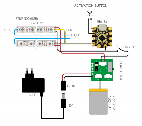
Since everything must function autonomously, we have added a rechargeable battery, a lithium one to be specific, it’s a 3.7 V – 1000 mA cell battery, that will be mounted on the sword thanks to a dedicated breakout board, which is small enough to fit into the hilt along with the battery and the rest of the electronics (except for the LED strips). The battery charger board is a breakout 004 based on the MCP73831T integrated circuit, an SMD encapsulated in a SOT-23 case produced by Microchip. The board typically accepts 5 V as input, which can come either from a common power adapter or from a miniaturized solar panel, but also from the USB connector of the computer; from the S+ and S-terminals, the power voltage reaches the (VIN) input of the MCP73831T (U1) charge regulator, which allows inputs ranging from 3.75÷6 volt and provides the necessary current on the output to charge the Li-on or Li-Po elements with an output up to 550 mA. The battery (that must be connected to the +/- BAT contacts) theoretically has unlimited capacity, because it charges in a very long time at its peak, however, consider that with a 550 mA current, a 550 mAh element can be charged in an hour, a 1.100 mAh will require 2 hours, a 5,5 Ah will take 10 hours and so on. Charging status is indicated by the LD1 light diode which lights on during recharge and lights off when the charge is complete or when the VBAT output is not connected to any battery. This output is the battery line.
The batteries charge current is 454 mA at the moment, but it can be modified by changing R1 value according to the formula:
Ireg = 1.000/R1
Where value is measured in ohms if Ireg current is expressed in A.
Now, let’s move to the brain of the lightsaber, which is an essential version of Arduino called Beetle. The Beetle board was created by the American DFROBOT (www.dfrobot.com) and it is based on the ATMEL ATmega32U4 microcontroller, the same one used on Arduino Leonardo, Micro boards and others. Dimensions are very compact (20 x 22 x 3.8 mm) hence the name Beetle. In order to reduce dimensions, there are very few pins available on the Beetle but there still is a USB interface for direct connection to the PC and power (e.g. micro USB connector), which in this case is 5 V stabled, also applicable to dedicated pads, besides the possibility to take the voltage from the micro USB plug. There are 10 accessible pins other than the power pins, and the peculiar thing is that 9-pin and 10-pin can also be configured as A9 and A10 analog inputs. However, pins SCL, SDA, TX, RX, MISO, MOSI, SCK and RST are on the back.

The reduced quantity of available I/Os on the external side and the small dimensions of the Beetle, besides its low-cost, make the board more fitting for gadgets and tech toys.
Our Beetle is running a sketch that uploads the library to manage Neopixel strips and then reads the status of the activation button (connected to D11 line): as long as this is not active, the board is in standby, and as soon as you press it, the microcontroller wakes up and launches the light effect display, consisting in the progressive activation of the LEDs, which simulates the light saber from Star Wars; by releasing the button, the LEDs are progressively turned off, simulating the laser retreating, also in true Star Wars fashion.
The whole system can be turned off by operating a slide switch which also cuts power from the Bettle and therefore from the Neopixel strips; battery stays connected to the breakout 004, although it doesn’t absorb anything, at least when it is powered by the jack connected to terminals S+ e S-. The jack must be connected to the power adapter for recharging the battery, which can be the classic standard 5 V, 500 mA wall-cube.
Please note that, given the firmware’s functioning, if you apply a voltage to the Beetle using the switch and the activation button is closed, the color selection routine is launched: the Neopixel strips sequentially show each color and animation patterns; when the sword shows the desired color, you turn it off using this light switch. Once you turn it on again, Arduino Beetle will launch and use your selection.
Let’s finish the circuit analysis by mentioning the Neopixel strips, which we have already found in many projects, such as the “Back to the future flux capacitor”.

The strips are managed in parallel with just one line of Arduino, which is easily editable in our case by specifying it in the sketch; D9 is the default. Communication with the strips is unidirectional and references to a group of LEDs, which are 106 in total in our case. Neopixel strips are composed of “smart” RGB LEDs with integrated controller, easily manageable by Arduino thanks to the proprietary libraries, free to use. A peculiarity of Neopixel LEDs is that they can be connected to cascade so that the data line from one strip moves on to the next strip.
Each RGB LED can be individually managed through a dedicated comment inserted in the serial string and can produce up to 256 hues of its own color, for a total of 16,777,216 combinations of colors. To be more precise, command protocol of Neopixel involves sending out groups of three bytes in a 24-bit string, each one containing the lighting status of each base color (green in the first eight bits, then red and then green).
The data channel used for communicating with the Neopixel LEDs and therefore with the strips is similar to oneWire; the communication speed can reach a maximum of 800 Kbps. In our case, the LED scan frequency is 400 Hz for each strip.
In our project, we pilot the two Neopixel strip segments in parallel, connected to D9 line of the Beetle through the pins DI. The strips power is taken from + and – 5 volt pads of Arduino since the power absorption of each strip doesn’t go over the allowed limits. Reference ground for power and data (only one, found on G terminal of the strip) is still Arduino’s and connects to the GMD of the board.
Practical creation
Okay, now that we have explained how the electronics work, that’s move on to assembling our sword, for which you will need a handle and a rod, and you are going to apply the Neopixel strips on each side of the rod; the hilt that is going to enclose the electronics, can be 3-D printed in gray (or black) PLA using our 3Drag printer. To this purpose, you will find the necessary STL’s, along with the project files, on our website. In the figure, you can see the expanded view of the plastic parts composing the mechanical section of the lightsaber.

In order to make the strip’s light more uniform, we suggest inserting the rod in a translucent plastic white tube that you can find at any DIY store.
The Neopixel LEDs used in the project are two strip segments that can be found at our store. The battery will go under the lid of the hilt, and then secured in place with two self-threading screws; please note that the lid is designed so that, if the screws are not too tight, you can easily remove it by rotating it just enough to move the large sockets corresponding with the heads of the screws. The electronics must be wired and inserted from the top, before connecting the lithium battery, maybe also by adding a piece of cardboard to separate board and battery. The power button must be screwed on the hilt and on the bottom of it, in the dedicated socket, you’re going to insert the slider switch, by gluing it with sealing silicone or hot glue; on the hilt, you are also going to mount the jack for recharging the battery.

Please note that the sketch must be uploaded on the Beetle before inserting the board in the hilt of the lightsaber. Once you have mounted everything, turn on the sword by pressing and holding the button, choose a color and turn off using the switch. Once you turn the lightsaber on again, you will be ready for… Space Duels!!!
From openstore
STRIP 300 LED RGB ADDRESSABLE WS2812B- NEOPIXEL
Lithium battery charger – mounted
Compact switching power supply 5 Vdc / 2 A plug DC output

but pssssst – never ever tell anybody what sketch and/or where to find it!!