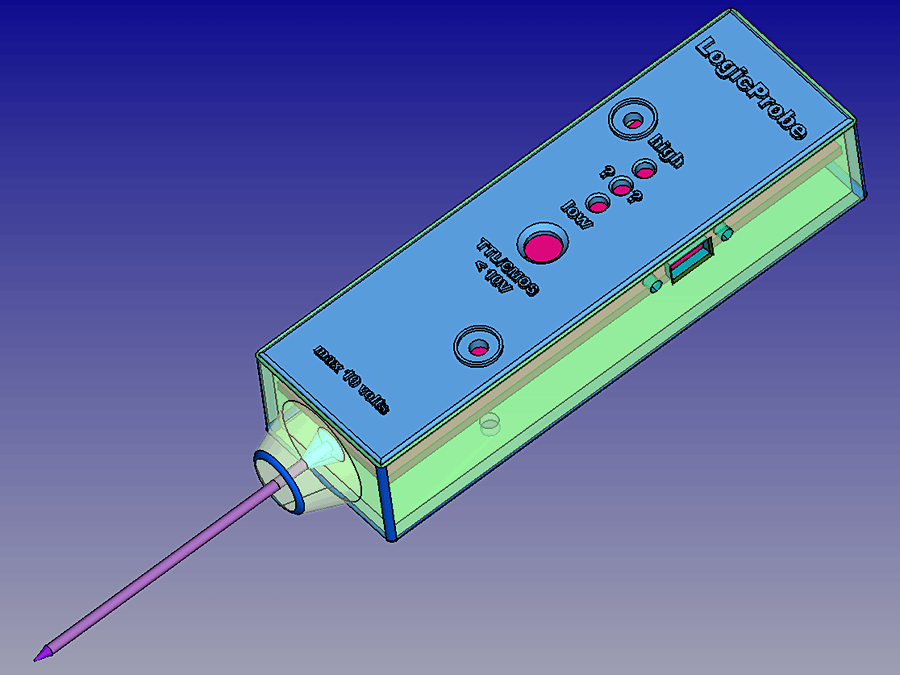
In this project we see how to build a logic probe, that is a complete, simple and effective instrument that allows you to measure digital logic levels 0 and 1, both in TTL and CMOS technology.
The maximum accepted level is 10 volts but CMOS can reach up to 18 volts (however best avoided). To use it just connect the Mini USB cable with black ‘crocodile’ clip to the GND of your circuit, touch the probe whose logic level you want to know (in the same circuit) and watch the corresponding LED that will light up. In addition there is a complete circuit to recharge the LiPo battery.
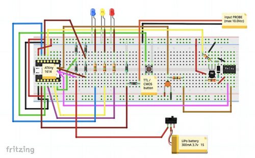
The small MPU board is a double-sided PCB with SMD components: there is the ATtiny processor (programmed with Arduino Nano and his IDE), a USB mini, two capacitors, a resistor for the LED and finally the 3.3v voltage regulator, this is the scheme:

I am interested in Build a logic Probe TTL / CMOS