Designed to be coupled to an irrigation controller, a weather station or motorized curtains and rolling shutters, it shuts down a relay when rain is detected.
One major issue when dealing with sprinkler controllers is rain starting to pour during sequences execution, because in this case it is useless – if not damaging – to water a garden or plants while nature is already taking care of that; not to mention that pouring additional water on soil that has already been hit by pouring rain may lead to collapse of drainage canals or ditches, manholes or catch basins, besides causing garden or courtyard floods. Another issue is water stagnation once the rain stops pouring, because this is another instance where garden watering is of no use, since there already is a surplus of water.
In order to bypass said obstacles, a sprinkler controller worthy of its name must include a sensor capable of detecting pouring rain and water on the ground beside being obviously able to handle signal coming from said sensor and consequently stop or delay execution of irrigation sequences; this latter aspect is assigned to programming and is currently taken into account in sprinkler controllers, which have a dedicated input, typically a clean-contact or resistive input with pull-up.
Once input is activated, the controller executes expected action, skipping the cycle or just putting it on hold for a period of time believed to be sufficient (e.g. a couple of hours) for water to run out; said period of time must start from sensor deactivation, that is when water presence is no longer detected.
Our Project
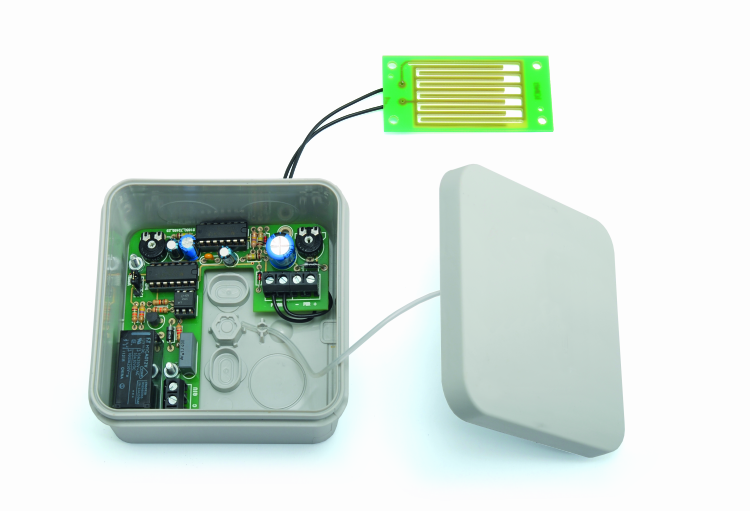
We are proposing you the realization of an electronics-aided sensor that allows us to use it not only to stop a sprinkler system’s cycle, but also to send a closing signal to a motorized curtain or rolling shutter; in fact, the sensor output is composed by a relay, therefore offering a clean contact. This way, it’s not just a simple sensor but a real control unit that can be adjusted to sprinkler controllers, motorized curtains or rolling shutters, but also to various applications where there is the necessity to detect the presence of rain or water on the ground, e.g. flood sensor in a basement or a warehouse.
The circuit is substantially composed by a (monostable) timer and a bistable capable of executing two different tasks upon detection of the same event; said event being a decrease of the resistance value between 1-pin and 2-pin of U1 NAND and ground, which corresponds to the contact of interdigitated-electrodes sensor with water.
When this happens, a timer is triggered; this timer keeps a logic level for a set amount of time within certain limits; a bistable is also triggered, which remains excited; this configuration allows for a very versatile circuit, in fact, timer can be used for instance to stop time-controlled irrigation controller, or to drive a monostable signal emitter, but also to send an impulsive signal to a circuit tasked to activate a curtain, a rolling shutter etc.
On the other hand, the bistable is designed to activate the usual irrigation controller or the one controlling motorized curtains and rolling shutters, however a stable level is to be used when necessary, that is a command that, once the event is detected, will not de-activate again till manual intervention or incoming reset signal.
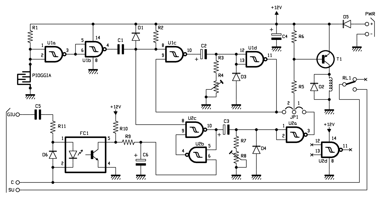
Analyzing the circuit diagram will allow a better understanding of the above. Let’s take a look at the next page right here, showing circuit’s composition: we find a monostable composed by logic gates U1c e U1d (both NAND from a 4093 containing four NANDs with Schmitt-trigger inputs, a solution allowing more precise switching around threshold logic level) and a bistable composed by U2b and U2c NANDs. Both stages are triggered by the buffer composed of U1a and U1b NANDs, cascade-connected and configured as logic inverters, used to acquire sensor-determined tension: when sensor is dry, 1-pin and 2-pin are kept at logic 1 by pull-up resistor R1, while if sensor gets wet enough that water closes contacts, resistance drops to such a value that 1-pin and 2-pin are no longer capable of keeping logic 1; in this case, 3-pin switches from 0 to 1 and U1b output goes low, dragging the C1 casing to which it is connected to around 0 volts. This leads to a logic zero impulse on U1’s 8-pin, lasting around R2 x C1, which excites both monostable and bistable; let’s see what happens in the former, supposing C2 is discharged and U1d output is high: in such conditions, when one input is a logic zero and the other is 1, NAND prior having both inputs at 1 and output at zero sees 10-pin going high. Since C2 is empty, said level is found on U1d inputs, configured as NOT, which now takes its output to zero, maintaining monostable’s current condition although 8-pin goes back to logic 1 (because C1 charges up or sensor goes back dry); meanwhile, electrolytic C2 starts charging up – due to logic 1 on U1c’s output – through series resistors R3 and R4 and reaches such a voltage between its plates that U1d inputs go low in a time roughly equal to product of said series resistors and its capacitive value. Since R4 is a trimmer mounted as a rheostat, charging time may be adjusted to an extent in order to suit one’s needs, so we can set monostable duration as we see fit; since R4 is 10 MΩ, time can vary between a few fractions of a second and a bit over 10 seconds. Once C2 has sufficiently charged up and is capable of retaining most of the voltage supplied by U1b, U1d output switches from zero to logic 1 and brings back to this state 9-pin of U1c; at this point, since C1 has charged up and 8-pin is also at logic 1, U1c’s output goes back to logic zero and causes rapid (almost instantaneous) discharge of C2 through diode D3, which is now in direct polarization and conducts current, at least as long as its work voltage is over 0,6 V. This reactivates monostable, thus making it ready once again for a new work cycle. If JP1 is closed between central contact and 2, when monostable is excited and for the whole duration of its temporization, T1 transistor’s base is polarized from low state and enters saturation mode, powering RL1 relay’s coil and closing exchange between C and NO, therefore short-circuiting C and SU contacts on the terminal board; by connecting those to the controller of a motorized curtain or rolling shutter, this is instructed to lower. It is understood that point C goes to the system’s common point (i.e. motors’) and that if we are controlling an awning, SU must be connected to the button to lift the awning (because when it rains awning must be pulled back).

Note that we can adjust timer duration so that it last just a bit longer than request for lowering state of full opening, after all if relay’s contact closes down longer than necessary we are sure motors won’t get damaged, since they have a built-in limit switch that cuts off power as soon as opening/closing mechanism reaches maximum/minimum extension.
Now, let’s take a look at what happens inside the bistable, which, for the purposes of controlling the relay, can be used as an alternative to the monostable, moving JP1 Jumper to contact 1: upon powering on circuit, if we suppose C6 is initially empty, U2b NAND finds 6-pin at logic 0, and this is enough (since it’s a NAND) to force its output to 1. If we suppose sensor is dry, given that 8-pin of U2c NAND is also at logic 1, the latter’s output is zero and takes back that condition to 5-pin of the same U2. Under this condition, we are sure U2b will keep output at logic 1.
Now, is we suppose rain sensor get wet enough so that water connect interdigitated contacts, we find the same logic 0 on u1b’s output, determining a low-level impulse between node D1-C1 and ground and therefore to 8-pin of U2c; this causes 10-pin to switch to high level, then a high-level impulse passes through C3 capacitor and it keeps U2a’s inputs at high-level till, while C3 is charging, voltage across series resistors R7/R8 drops below ¼ of power source. This normally happens after a period τ, the time constant which is equal to the product:
τ = (R7+R8) x C3
The time constant is in seconds if the sum of resistance values is expressed in MΩ and C3 in µF.
As long as 1-pin and 2-pin of U2a stay at the high level, 3-pin of U2 goes to logic 0 and stays there, determining once again saturation of transistor and activation of the relay, which closes contacts down and C.
Since R8 is a trimmer, time U2a’s output stays at logic 0 and relay closes down can be adjusted from fractions of a second to over 10 seconds. Once C3 has enough charge, a voltage equals to logic 0 can be found between 1-pin and 2-pin of U2a, relays go back in standby because 3-pingoes high and T1 goes back in interdiction state.
Unlike what happens in the monostable at the top of the diagram, this one can’t be re-triggered, meaning that the cycle we just mentioned will take place just once, in fact U2c and U2d form a bistable which, once received logic-0 impulse, stays in this condition till reset, which is obtained by bringing 6-pin of U2 to high level. This happens if DOWN input is powered by alternating voltage; this input is designed to reset monostable when someone accidentally presses the button for lifting motorized rolling shutter, in order to prepare both bistable and the monostable piloted by it for a new cycle.
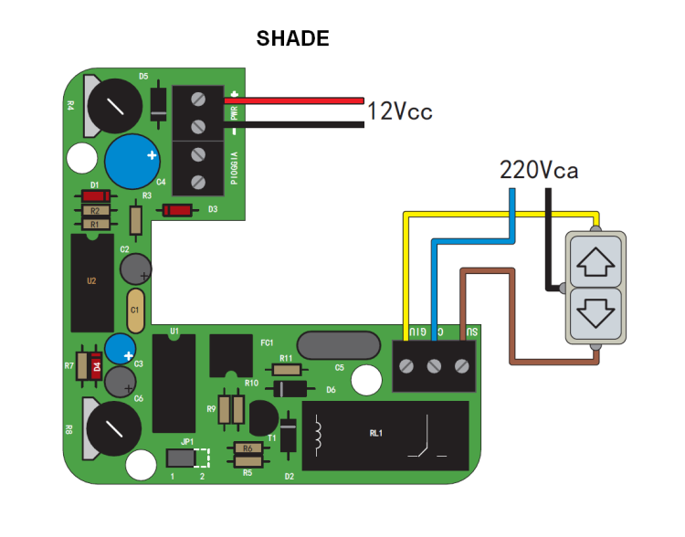
So, to recap, it is recommended to use the monostable at the top to provide a timed-controlled command to a motorized rolling shutter or a sprinkler controller, while the one at the bottom provides a stable command which de-activated if we come back home and decide to lower curtains again. We have to mention that, given the structure of the circuit, if the rain keeps wetting the sensor, we have the option to lift the rolling shutters again, but then this will go back down automatically one released DOWN button. The circuit used to detect command and reset bistable is made with a photocoupler composed of a LED as input device and an NPN transistor as output; by connecting DOWN to the output of the button used to lower the rolling shutter and C to common, that is to say the two contacts placed at the opposite ends of the motor, when we activate rolling shutter contacts receive 220 Vca and alternating voltage passes through C5 capacitor (which party lowers voltage) and on R11 resistor, used as RC impedance to limit LED current of photocoupler. Capacitor’s value is 100 nF and, at utility frequency of 50 Hz, has a capacitive reactance of:
Xc = 1/(6,28 x 50Hz x 0,1 µF)
= 31,85 kΩ
In series with 8,2 KΩ R11 resistor, capacitor forms an impedance which value is enough to allow LED polarization in the FC1 with a current of around 5 mA, enough to saturate output phototransistor and discharge C6 capacitor, which is inserted in order to stabilize logic state on 6-pin of U2 and to filter possible noise that may lead to false switching of the bistable. The diode in parallel to LED of the photocoupler protects it from negative half-waves, and since it is in interdiction, it should be able to resist alternating voltage skies, which is over 300 V.
Photocoupler has been inserted in order to create a galvanic separation between circuit powered by utility voltage and low-voltage circuit, that is section powering logic gates, FC1 output stage, T1 transistor and sensor; this section is powered by a direct voltage of 12÷14 V through terminals + and – PWR; D5 diode protects this line from inversion of polarization that might accidentally occur when making connections.
Usage Notes
Connection to the system to be used will be made as illustrated in wiring pictures you can find on the next page, depicting systems for motorized rolling shutters and motorized curtains.
All cables can pass through holes drilled in the bottom or on the sides, which are then to be filled with sealing silicone in order to protect the circuit from humidity, possible high waters or dust; silicone must be left to dry out for at least a couple hours before moving cables.
Once finished assembly, apply interdigitated sensor on the ground or in the garden (simply put down or fixed, although not using nails or at the very least not with metal nails) if you are going to use it as rain sensor, you will then connect it to the board using wires of desired length: a small-diameter twin-lead for electric systems is good. Length is not critical, just do not exceed 20 m otherwise interferences from 230 Vca network cables might cause big enough disturbances to make input logic gates (U1) switch levels. If you have to “pull” longer connections and want to make sure you’re safe from interferences, use a shielded coaxial cable or a two-conductor cable with a shield; in this case, conductors will be connected to contacts of printed circuit labelled RAIN and shielding sleeve must be connected to electric system’s ground, where accessible, or to the ground of circuit’s power supply.
If you are going to use the device as flood sensor for basement or in any room, place sensor on the ground (you can glue it to the ground using clear silicone), connect (well-isolated) cables to the circuit and you will be able to control both the input of a flood alarm controller (generally, a technological alarm controller…) or you will be able to directly control a visual or acoustic single-emitter, but you could also control a GSM remote monitoring in order to send an SMS in case of flood.
Please note that interdigitated-contacts sensor can also be used to detect liquid spillage other than water (if electrically conductive) such as oil, liquid cleaners etc. It does not detect, however, distilled water, since in theory, it lacks dissolved ions, therefore, it’s electrically isolated. In any case, avoid using the interdigitated-contacts sensor with high-flammable liquids (solvents, fuel), because, even if it works with low voltage, it’s always better to avoid useless risks.
If you want to use the sensor to communicate a rain situation to a weather station, use the monostable (JP1 jumper on contact 2) with a shorter time, even just half a second; same thing if you want to connect the circuit to a technological alarm.
Well, we have reached the end, thank you and have a nice day!
From openstore

Great project and write up! I was curious as to what program or software tool did you use to create the connection diagram (i.e.image 1-1.png)?
Thanks in advance!
Cheers,
Sam