[youtube id=”5H85RDA5HEw” width=”620″ height=”360″]
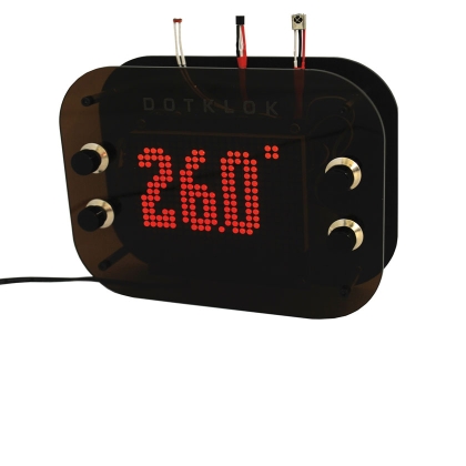
Today we present a mod of Dotklok, the product that we presented few months ago , with new features such as reading ambient temperature and controlling display brightness based on the ambient light. The whole thing can be controlled remotely via a standard TV remote control.
Open firmware and hardware have let many hackers to build and customize their own Dotklok, sharing the sketches they made to add or change Dotklok’s animations.
Let’s see now the two changes implemented: one is about hardware and the other is about software.
The hack inventor, Stefano Del Bufalo, added two sensors: temperature and light. Also a standard infrared 38 kHz receiver has been provided, suitable to receive commands from the classic IR remotes for televisions, DVDs, VCRs, set-top box etc. This allows you to send remote commands to Dotklok, that everyone can write freely in the firmware. In fact, the proposed solution contains the code implementation to read the remote control used by Stefano, but everyone could replace the code with one that is suited to his own.
In addition to these features, the firmware is modified to change the time representation mode.
Regarding the sensors, the temperature one allows, through an appropriate modification of the sketch, to represent the ambient temperature on the display as if it was one of the many animations already present in Dotklok.
The temperature probe chosen is the classic and well-proven LM35 by Texas Instruments, which provides an analog signal consisting of a10 mV DC voltage for each centigrade degree detected; the LM35 provides the temperature value with an accuracy of 0.5 ° C in a measuring range of between -55 and +150 ° C. The chip has three pins, two of which are for the power supply (4 ÷ 30 Vdc), while the middle one provides the analog voltage that expresses the recorded temperature. Since the LM35 gives 10mV / ° C starting at 0 K, 0 ° C – corresponding to 273.15 K – determine a 2.7315 volts output .
The second sensor allows you to activate or exclude the automatic adjustment of display brightness according to the ambient light, to avoid the LEDs to get annoying or hardly visible.
The reading of the temperature probe and photoresistor info is done by applying corresponding voltages to the analog inputs of Arduino. In particular, the photoresistor that has a value of about 20 kohm in full darkness, is connected in series with a 1 kohm fixed resistance, in so as to form a voltage divider powered by +5 V. In order that the reading takes place correctly, also the Vref pin of Arduino must be brought to this voltage.
The remote control
The latest variation is the addition of a remote control, implemented with a few lines of code. This function allows you to read the signals sent by the common IR remote control used in TV, decoder, etc.. With this change you can make most of the Dotklok functions controllable remotely, as to replace the remote control buttons to buttons already present.
In the code examples provided by the creator, the remote control allows you to switch from animation to another while sitting on the couch, or, still remotely, turn off the light sensor to set manually the display brightness. In fact , once a sensor and a sketch that reacts to pressing any button of any remote control introduced, the only limit on the introduction of new functions, it your creativity. In fact the best of this solution is that it does not need a specific remote control, but the system can learn the codes of the most part of remote controls, provided that operating with 38 kHz carrier data. To do this, just set the Dotklok in DEBUG mode to see on the serial monitor (Arduino’s IDE Serial Monitor) which values are connected to the various buttons of any remote control, and insert these values in the sketch; we shall see shortly how to learn the codes directly from the display, instead of from the Serial Monitor.
New firmware
Unfortunately to achieve all this, you must give up some animations because of the lack of space in the ATMega328P microcontroller. in this case the author has given up on “percent_time”, “random_dot_time”, “morse_time” and “game_time” , that have been removed by the firmware. Besides, who wants to recover more space than that of the author, can follow the instructions in the prof. Michele Menniti’s guides, by suitably modifying the file board.txt for ATMega Stand-Alone programming with the ISP method. The features added and the one removed involved a substantial modification of the sketch, as regards the setup part.
The sketch sent by the creator (downloadable from here) is updated to be included with the Arduino’s IDE 1.0.1 and the related libraries (the current RTClib, for example) support all IDE versions.
The updated RTClib library already contains the control of the IDE version. To check IDE version, the creator added the following lines to the Button library – contained in the file Button.h:
#if (ARDUINO >= 100)
#include <Arduino.h>
#else
#include <WProgram.h>
#endif
Library ht1632 however, is the same published by us for the original Dotklok.
// LM35 sensor
int pin_lm35 = A1;

// IR sensor Remote Control
int pin_IR = 12;
#include <IRremote.h>
IRrecv irrecv(pin_IR);
decode_results results;
int ir_mode = 0;  //int ir_mode = 2 (test IR) - int ir_mode = 0

int c;
boolean remote_control = false;

int pin_fotoresistenza = A0;
int fotoresistenza_val;
int lux_val = 10;
boolean fotoresistenza_stato = true;
Here you can see the declaration of the variable for the modified sketch.
Notice the lines:
// LM35 sensor
int pin_lm35 = A1;
which concerns the addition of the temperature sensor and:
// IR sensor Remote Control
int pin_IR = 12;
which refers to the IR remote control.
For this feature, load the library IRremote.h:
#include <IRremote.h>
For this project to work you must import the library IR Remote 0.11, other versions may not work.
Regarding the remote control, the combination is performed in the following way: first you need to bring Dotklok in mode 2 (IR test) changing the line int ir_mode =0; in Listing 1, substituting 2 to 0 until the line become int ir_mode = 2;.
At this point, aim the remote at the 38 kHz IR sensor, remaining at least half a meter away and transmit using the buttons that you want to connect with the Dotklok functions. Thanks to the function change implemented by Mr. Del Bufalo, the Dotklok display directly shows the number corresponding to the code of the pressed button.
Simply take note of the numbers and then replace in the function “press_remote”, so the system will recognize the buttons you want.
To test IrRemote, which is the reading function of the IR remote control, you must set the variable int ir_mode = 2;,which transforms the DOTKLOK in a remote control tester. You can use any remote control, but if you see too many “0” (zero) when the various buttons, it is possible that it does not work at 38 kHz, so the system cannot detect it.
The sketch provided by the author contains, in the “press_remote” function, the hex codes contained and returned by a remote control in his possession.
In the author’s example, using the remote control, you can:
A) Change modes 0, 1 and 2 (i.e. the value of ir_mode)
-
In mode 0 (the first LED in the top left turns on for one second) with the + and – buttons you can change animation.
-
In mode 1 (the second LED in the top left turns on for one second) with the + and – buttons you can change the display brightness.
-
In mode 2 (the third LED in the top left turns on for one second) debugging for remote control is activated, in fact when any key is pressed on any remote control the hexadecimal code that returns is displayed.
B) Enable or disable the automatic brightness of the display according to the ambient light: press once to switch it off, you will see a minus (-) in the lower left corner, press again to turn it on and you will see a plus (+) at the bottom left. Keep in mind that using mode 1, this function is automatically deactivated.
The firmware section that manages the IR remote control is shown here:
// press_remote
press_remote(){

    if (irrecv.decode(&results)) {

    String ir_val = String(results.value, HEX);
    // legge il codice esadecimale letto dal sensore IR

    if (ir_mode==0 && ir_val==”15”) {
            animation++;
            if(animation > ani_max)  animation = 1;
            delay(50);
    } else if (ir_mode==0 && ir_val==”16”) {
            animation--;
            if(animation < 1)  animation = ani_max;
            delay(50);
    } else if (ir_mode==1 && ir_val==”15”) {
            lux_val++;
            fotoresistenza_stato = false;
            ht1632_sendcmd(11, HT1632_CMD_PWM + lux_val);
            delay(50);
    } else if (ir_mode==1 && ir_val==”16”) {
            lux_val--;
            fotoresistenza_stato = false;
            ht1632_sendcmd(11, HT1632_CMD_PWM + lux_val);
            delay(50);
    }

    if(ir_val==”30”)
{
            ir_mode++;
            if (ir_mode > 2) { ir_mode = 0; }
            plot(ir_mode,0,1);
            delay(1000);

        } else if(ir_val==”12”)
{
            if (fotoresistenza_stato) {
                fotoresistenza_stato = false;
                plot(0,13,1);plot(1,13,1);plot(2,13,1);
            } else {
                fotoresistenza_stato = true;
                plot(1,12,1);
                plot(0,13,1);plot(1,13,1);plot(2,13,1);
                plot(1,14,1);
            }
            delay(1000);

        } else if(ir_val==”11”)
{
            // test Funzione 3
            plot(1,15,1);
            delay(50);

        } else if(ir_val==”10”)
{           // test Funzione 4
            plot(2,15,1);
            delay(50);

        } else if(ir_mode==2)
{
            ht1632_clear();
            int step = 0;

            char char_print[10];
            ir_val.toCharArray(char_print, sizeof(char_print));

            scroll_text(char_print);

            delay (500);
        }

        irrecv.resume(); // Pronto per il prossimo segnale

        return true;
    }

    return false;
}

void luce_ambiente(boolean fotoresistenza_stato) {

    if (fotoresistenza_stato) {
        fotoresistenza_val = analogRead(pin_fotoresistenza);

        lux_val = map(fotoresistenza_val, 1023, 700, 0, 15);
        if (fotoresistenza_val<700) { lux_val = 0; }
        ht1632_sendcmd(11, HT1632_CMD_PWM + lux_val);
    }

}
//--------------------------------------------------------------
You must write in the code portions if (ir_mode == 0 && ir_val ==”15″) the numbers corresponding to the transmitter buttons that you have obtained during the test in test mode. The number following _val == should be replaced for the various buttons with the codes corresponding to the animation that you want to control.
In Listing 2, the following code portion:
if (ir_mode==0 && ir_val==”15”) {
animation++;
if(animation > ani_max) animation = 1;
delay(50);
} else if (ir_mode==0 && ir_val==”16”) {
animation–;
if(animation < 1) animation = ani_max;
delay(50);
defines the codes of the buttons assigned to the scroll backward and forward in the animations (mode 0): pressing of the key identified by the code 15 scrolls forward, that of button 16 lets return to the previous animation. If the keys that you have chosen correspond to other numbers, enter these instead of 15 and 16.
Again in Listing 2, the code portion:
} else if (ir_mode==1 && ir_val==”15”) {
lux_val++;
fotoresistenza_stato = false;
ht1632_sendcmd(11, HT1632_CMD_PWM + lux_val);
delay(50);
} else if (ir_mode==1 && ir_val==”16”) {
lux_val–;
fotoresistenza_stato = false;
ht1632_sendcmd(11, HT1632_CMD_PWM + lux_val);
delay(50);
defines the function of the 15 and 16 keys if the Dotklok is in mode 1 (dimming). The observations just made for the mode 0 are similarly valid.
 The calls to the various functions involved in the new firmware is shown here,which covers the system setup. Here’s a freely call in the setup() “analogRead(pin_lm35);” that is used in the photoresistor management.
/***************************************************************
 * traditional Arduino sketch functions:
 and loop.
 **************************************************************/

void setup()
{
  // init the button inputs
  pinMode(4, INPUT);
  pinMode(5, INPUT);
  pinMode(6, INPUT);
  pinMode(7, INPUT);
  pinMode(8, INPUT);
  digitalWrite(4, HIGH);
  digitalWrite(5, HIGH);
  digitalWrite(6, HIGH);
  digitalWrite(7, HIGH);
  digitalWrite(8, HIGH);

    // debug mode forced by B4 pressed during start up
  if(!digitalRead(7))  DEBUG=true;

  if(DEBUG){
    Serial.begin(57600);
    Serial.print(“DOTKLOK “); Serial.println(REV);
    Serial.println(“DEBUG true, serial port open at 57600”);
    //Serial.print(“Avail mem = “);
    //Serial.println(availableMemory());
  }
  else{
    Serial.begin(57600);
    Serial.print(“DOTKLOK “); Serial.println(REV);
    Serial.println(“DEBUG false, serial port now closed”);
    Serial.end();
  }

  // display screen setup, software version display, (and test)
  ht1632_setup();
  ht1632_clear();
  putchar_3x5(6, 5, REV[0]);
  putchar_3x5(12, 5, REV[2]);
  putchar_3x5(18, 5, REV[4]);
  plot(10, 9, 1);
  plot(16, 9, 1);
  delay(1000);
  if(DEBUG)  screenTest();

  // general set up
  //pinMode(13, OUTPUT);
  randomSeed(analogRead(0));

  // RTC setup
  Wire.begin();
  RTC.begin();

  if (!RTC.isrunning()) {
    if(DEBUG) Serial.println(“RTC is NOT running!”);
    // following line sets the RTC to the date & time this sketch was compiled
    RTC.adjust(DateTime(__DATE__, __TIME__));
  }
  else {
    if(DEBUG) Serial.println(“RTC is running.”);
  }

  // test buttons
  /*
  while( b5.isPressed() ){
    for(int i=0; i<4; i++){
      if( buttons[i].isPressed() )  plot(i,0,1);
      else                          plot(i,0,0);
    }
  } */

    //--------------------------------------------------------------
    //#### introduzione nuove funzionalita’ (Stefano Del Bufalo) inizio
    //--------------------------------------------------------------
    // Avvio ricevitore IR
    irrecv.enableIRIn();
    // settaggio pin fotoresistenza
    pinMode( pin_fotoresistenza, INPUT);
        analogRead(pin_lm35);
    //--------------------------------------------------------------
    //#### introduzione nuove funzionalita’ (Stefano Del Bufalo) fine
    //--------------------------------------------------------------

} // end setup()

void loop()
{
  // all time and button checking handled in animation fucntions
  // main loop just handles animation number (init. to 1)
  // bound the animation number
  //animation = constrain(animation,1,ani_max);
  //if(DEBUG)  animation=6; // used to force any animation during testing/debugging
  if(DEBUG) { Serial.print(“loop / animation: “); Serial.println(animation); }

  // run the clock animation
  switch(animation) {
  case 1:
    big_time();
    break;
  case 2:
    basic_date_time();
    break;
  case 3:
    scroll_time();
    break;
    //------------------------------------------------------------
    //#### introduzione nuove funzionalita’ (Stefano Del Bufalo) inizio
    //------------------------------------------------------------
  case 4:
    temperatura_time();
    break;
    //--------------------------------------------------------------
    //#### introduzione nuove funzionalita’ (Stefano Del Bufalo) fine
    //------------------------------------------------------------
  } // end switch(animation)

} // end main loop

//--------------------------------------------------------------
//#### introduzione nuove funzionalita’ (Stefano Del Bufalo) > time_animations.h
//--------------------------------------------------------------
// temperatura_time
void temperatura_time(){

    long millis_now = 0;
    long millis_temp = 0;
    long gap_temp = 1000;

    boolean power_up = true; // used to force time display on function startup

    /* INIT DISPLAY */

    ht1632_clear();

    /* TIME LOOP */
    do{ // exit based on button presses, checked later in loop

        //========================================================
        // Lettura Sensore Temperatura
        //========================================================
        millis_now = millis();

        if (millis_now - millis_temp > gap_temp )
        {   // Refresh Sensore Temperatura ogni “gap” sec
            millis_temp = millis_now;

            float tempLM35 = (5.0 * analogRead(pin_lm35) * 100.0) / 1024.0;
            // (5.0 tensione di alimentazione)
            int tempcalc = tempLM35 * 10.0;

            String str_temp = String(tempcalc, DEC);
            char char_print[3];
            str_temp.toCharArray(char_print, sizeof(char_print));

            int step = 0;
            for (c = 0; c < 3; c++){                         // tre cifre in tutto
                putchar_5x12(1 + step, 2, char_print[c]);
                step = step + 6;
            }

            plot(12, 13, 1);

            plot(19, 1, 1);
            plot(20, 1, 1);
            plot(19, 2, 1);
            plot(20, 2, 1);
        }

        /* CHECK BUTTONS, return if necessary */
        if( change_animation() )  return;
        if( press_remote() ) return;
        luce_ambiente(fotoresistenza_stato);

    }while(1);

} // end function temperatura_time
//--------------------------------------------------------------
Note that currently, as the divider whose the photoresistor is part is connected to +5 V, the reference for the ADC of Arduino’s ATmega328 is also set to 5 volts. To increase accuracy, you could use “analogReference (INTERNAL) “, which sets AREF to 1.1 volts: by doing so, the 10-bit of the converter would lead to a resolution of about 1 mV, but in this case is necessary to recalibrate the photoresistor values.
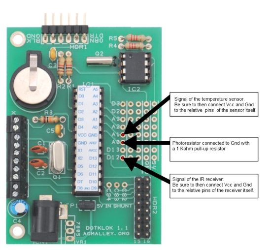
Hardware
Some hardware modifications to the control circuit of Dotklok – presented in the circuit diagram that could find here – are required to obtain the described functions. This diagram should be modified as in that in these pages, i.e. by adding the photoresistor with its 1 kohm resistance to the 5 volts positive, and the probe LM35.

Regarding the probe LM35, we must say that supplying a DC voltage in output and being powered by the same 5V line which powers the LED matrix, may induce fluctuations in the temperature signal due to the absorption by the 5 volt line. This drawback, although insignificant, could be overcome by using a DHT11 or DHT22 sensor (with digital output) connected to a digital rather than analog pin, but this would imply writing the code to acquire the data from the new probe and the removal of that for the analog reading. This is to your choice.
The new firmware, contained in a zip folder, can be downloaded here.
The end result:

The Dotklok kit is available at our store.
