
We use an Arduino to program other ATmega without bootloader . This technique allows you to use all flash memory for code and make boards using new ATmega, cheaper than those with bootloader.
The qualities that have made the success of Arduino are undoubtedly the open-source software, many libraries, a good hardware and a virtually infinite Reference that explains each possible use of the platform.
But if we use Arduino for a specific use, we can integrate it into a specific circuit and program the micro in a way that performs a single firmware. We may so remove the bootloader and leave to the firmware the entire program memory.
The ATmega328 has 32 Kbytes of flash, that when the chip is mounted on Arduino are not all available, as a portion is reserved to the bootloader, the purpose of which is to communicate with the IDE Arduino to load programs (sketch) to be performed. The same bootloader, on each power on or reset of Arduino, verifies the presence of a sketch in flash memory and executes it. The bootloader occupies a space of 512 bytes, in the case of Arduino UNO.
Well, in a stand-alone application the bootloader no longer needed.

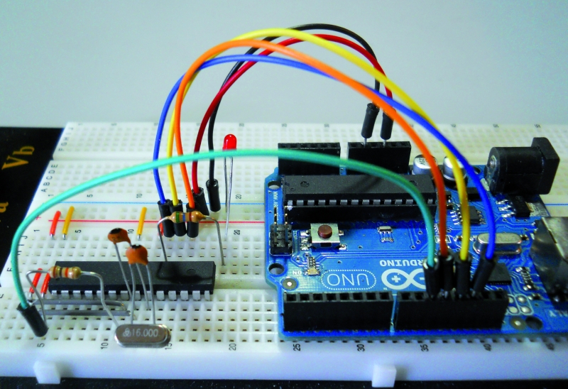
The configuration of the micro ATmega328P needs, in addition to the power (+5 VDC to pins 7 and 20, GND to pins 8 and 22), a 16-MHz crystal between pins 9 and 10, two 22 pF ceramic capacitors from between these pins and GND, a 10 k Ω resistor between pin 1 and +5 VDC for pull-up the reset line.
Programming ATMEGA in stand-alone

Anyone knows that it is necessary program Arduino uploading a sketch via USB, using the software called IDE and the operation is quite simple.

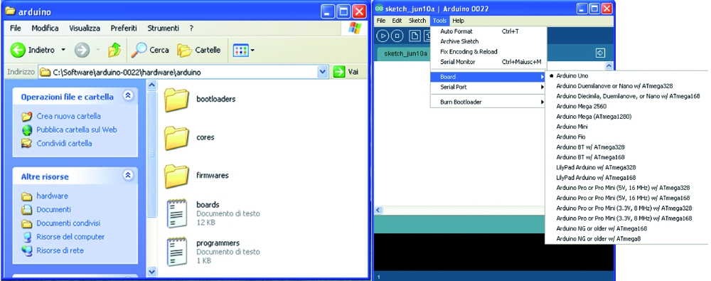
We can see a screenshot of the IDE with an Arduino sketch loaded and UNO during the receipt of the sketch (notice the yellow LED on).
The technique will test allows the use of a board Arduino as ISP Programmer.

We start with the list of required materials:
• Arduino UNO / Duemilanove (will be used as a programmer);
• ATmega328P chip (chip to be programmed);
• Breadboard and jumper;
• a crystal of 16 MHz, two ceramic capacitors from 22 pF, a resistance of 10 K Ω 1/4 W, a resistance of 560 Ω 1/4 W LED 3 or 5 mm;
• seven male-male jumper wires.
A resistance of 120 Ω 1/4 of watts, and an electrolytic capacitor or tantalum from 10 uF 10 ÷ 16 volts.
Now we prepare our target circuit and first of all insert the chip on the Breadboard, these are the connections to make:
• through the jumper to be Breadboard connect pins 7 and 20 of the chip to the positive supply line (+5 volts);
• in the same way we connect the pins 8 and 22 of the chip to the ground line supply (GND);
• connect pin 1 of the chip to the +5 V line through the resistor of 10 k Ω;
• insert the crystal to the pins 9 and 10 of the chip;
• insert the two 22 pF ceramic capacitors; both must have a leg connected to GND, while the other will serve to connect a capacitor to pin 9 and the other to pin 10 of the chip;
• insert one end of resistor 560 Ω at the pin 19 and the other end into an empty spot on the breadboard, and to this end we connect the anode LED(the longer pin) , whose other end (cathode) goes to GND;

At this point we can connect to the Arduino Breadboard using jumper cables under the following matches:
• Arduino pin 10 goes to pin 1 of the chip;
• Arduino pin 11 goes to pin 17 of the chip;
• pin 12 of Arduino is connected to pin 18 of the chip;
• pin 13 to Arduino pin 19 goes on the chip;
• the +5 V pins of Arduino goes to the positive supply line of the breadboard;
• any of the three GND pin of Arduino goes to the ground line of the breadboard.
Now look the software to reveal the “trick” that sends a sketch, using the IDE, to the chip on the Breadboard, bypassing Arduino that will play the role of Programmer ISP.

What we need to do is create a virtual board, starting from the original (corresponding to the model we are using Arduino) and making some simple but essential changes. We must first locate the file that is boards.txt containing all information relating to the various boards that the IDE shows us when we execute the command Tools->Board. Typically this file is located in the folder of the IDE software, the path X: \ mypath \ arduino-xxx \ hardware \ arduino, where X is the letter that indicates the logical drive and myPath the folder or location containing the program (xxx indicates the version of the program).
Now open the file with Notepad and see a long series of lines arranged in groups separated by a line consisting of a repetition of the symbol “#”,each group representing a different board. The lines are identified by the initial code, the same for all, but different for the board, the name that will appear in the submenu Tools->Board is inserted in the first row in the group.
The code is represented by the word “uno” which is at the beginning of each line.
The line containing the word “name” (usually the first) is followed by “=” and then the name that the board will have in the IDE.
Other information that concern us are:
• uno.upload.maximum_size = 32256: Sets the maximum capacity of flash memory that we can use in practice from 32 Kbytes of Flash which has the total ATmega328P we must subtract the space occupied by the bootloader, for the Arduino UNO is 512 byte;
• uno.bootloader.low_fuses = 0xff; uno.bootloader.high_fuses = 0xde; uno.bootloader.extended_fuses = 0x05; these three lines are the “fuse”, are used to set the behavior of the chip and are expressed with hexadecimal values;
• uno.build.f_cpu = 16000000L: This line must correspond to the clock frequency for which the chip has been set, by means of the fused, expressed in Hz, 1 Hz 6,000,000 correspond to 16 MHz, precisely the frequency of the quartz or, more precisely, the present external oscillator to Arduino UNO; this value is used as a reference for timing controls of the software, such as delay () and millis ().
And now we create our own virtual board, writing these lines of code:
atmsa16.name=ATmega in Stand Alone (w/ Arduino as ISP)
atmsa16.upload.protocol=stk500
atmsa16.upload.maximum_size=32768
atmsa16.upload.speed=115200
atmsa16.upload.using=arduino:arduinoisp
atmsa16.bootloader.low_fuses=0xff
atmsa16.bootloader.high_fuses=0xdf
atmsa16.bootloader.extended_fuses=0x05
#### atmsa16.bootloader.extended_fuses=0x07
atmsa16.bootloader.path=optiboot
atmsa16.bootloader.file=optiboot_atmega328.hex
atmsa16.bootloader.unlock_bits=0x3F
atmsa16.bootloader.lock_bits=0x0F
atmsa16.build.mcu=atmega328p
atmsa16.build.f_cpu=16000000L
atmsa16.build.core=arduino
Following the approach of the file will separate this group of lines to those of other boards, inserting a line of “#”.The end result should be:

We note that are varied: the code (atmsa16 instead of uno), the maximum_size (brought to its maximum capabilities of Flash, since we do not reserve space for the bootloader), then there a new line (atmsa16.upload.using = arduino: arduinoisp) that allows us to understand the IDE that will program the chip in stand-alone and not on the Arduino. Another new line is preceded by some “# # # #” that disables it, the reason is easily explained: the extended_fuses is set to 0x05, and in some special cases, during the transfer of the sketch could be an error bound the setting of this value.As we shall see later, simply change the following two lines of code:
 <em># # # # Atmsa16.bootloader.extended_fuses = 0x05</em>
<em>atmsa16.bootloader.extended_fuses = 0x0</em>7
thus activating the value 0x07 instead of 0x05, it will work out. Of course, this change should not be made before, but only if you get the error.
Program the micro
At this point we are ready for the final step: send our sketches to the chip mounted on the breadboard and then will test the operation separating it from Arduino.

To read the new board in the file, the IDE must be restarted, so if this program was open, when editing the file boards.txt must close it and restart it. To verify that our modification is successful, it is sufficient now run the command Tools->Board and check if there is now our “stand-alone” board, otherwise we should close the IDE and check the file boards.txt, because certainly we made a mistake.
The technique used to send the sketch to the chip in stand-alone mode is very simple: First select the Arduino board that we are using as a programmer (eg Arduino Duemilanove or UNO) , just as we do for normal use of Arduino. Then select the Arduino serial port (the COM for Windows users) and recall from the IDE the sketch ArduinoISP, execute this command by clicking the Upload button on the IDE. After several seconds of the three flashing LEDs and Arduino to the breadboard of course (at the moment is physically connected to pin 13 of Arduino that, as we know, check out one of the three LEDs on the board) on the IDE will come the message “done uploading “.
Arduino is ready to play the role of Programmer ISP, select, now, our board IDE “ATmega Stand Alone (w / Arduino as ISP)“, without changing the COM.
We load the sketch “blink” and execute it again by clicking the Upload button on the IDE: LEDs and Arduino breadboard flash again, this time for a much shorter period, after which the IDE will show the message again “Done uploading”.
So our ATmega328P chip was programmed without having to physically fit on Arduino and now lives its own life. It is then ready to be mounted in the circuit which it is intended.
Of course, the chip can be reprogrammed at will with any kind of sketch.
Troubleshooting
At this point we have to solve three types of problem that may occur when we send the sketch to the chip stand-alone. The problems of’extended_fuses and of autoreset may occur on either Arduino Duemilanove or Arduino UNO, without that you can establish a certain rule.We must also emphasize that the remedies that will illustrate to 100% solve the problems, but must be applied only if the problem occurs.
We start from the situation that may occur if we use a blank chip, the Atmel set the fuse to make the chip work at 1 MHz with the internal oscillator. If we send a sketch directly, happens that the chip in stand-alone ignores the external crystal and times will be staggered: for example, the LED blink with the sketch will last about 16 seconds instead of 1 second. Simply, we set the fuse, the operation can be done easily by loading the bootloader on the chip before sending the sketch.
Before explaining this simple maneuver quickly clarify two points: the bootloader is sent once a chip virgin and will only serve to set the fuse, then it will become useless and the sketch overwrite it, if we had to first load the sketch, noticing the error, and then load the bootloader, no problem: the chip is set and we just have to resubmit the sketch. The simple steps that are going to describe will return very useful for cases where we wanted to prepare a blank chip to work directly on Arduino; is a good idea to have in the house a spare chip with bootloader of our board, so if you were unfortunately damaged the original, a simple substitution solves this problem immediately.
Here are the steps to follow:
• prepare and connect the Breadboard Arduino as discussed previously;
• We open the IDE and select the model we are using Arduino and port to which it is connected;
• upload the sketch ArduinoISP to Arduino;
• now execute the command Tools->Burn Bootloader w / Arduino as ISP;
• After about a minute we loaded into the stand-alone chip the bootloader of Arduino boards (you may have noticed that in the IDE we’ve set our Arduino board).
As mentioned, the chip can be quickly mounted to receive the Arduino sketch, or leave it on the breadboard and repeat/execute the operation of sending the sketch stand-alone, this time the Blink will work perfectly.
Of course, other errors may occur, do not worry, keep reading this section and of course everything will be resolved.
So let the problem of ‘extended_fuses: the rows of our virtual board we expected a double value for this cast, because it can happen (even though it is quite rare) that some boards do not succeed in this program merged with the value 0x05. During the upload of the sketch on the chip with stand-alone mode, the IDE will display an error message (written in red on a black background) that will indicate the need to use the value 0x07, if it appears that in practice warning means that we must close the IDE, open the file boards.txt and activate the relevant line, simultaneously disabling the other (with 0x05), as explained above. At this point we can repeat the test. We clarify that if the error occurs on a given board will always occur on this board, so the variation of the files should be done only once and permanently.
And now we see the problem, more frequent, about autoreset. When the serial chip (FT232RL on Duemilanove or ATmega8U2 of UNO) receives a signal from the USB port, sends the reset pulse to ATmega328, who then prepares itself to receive Data. This operation corresponds to the one you make every time you press the button “RESET” on the Arduino.
If the data do not arrive or if the reset was made manually, the sketches in flash memory chip ATmega328 is executed. When Arduino is used as ISP Programmer can happen that, if the autoreset is sent too early, the upload operation fails. In this case the IDE returns the following error: “avrdude:stk500_getsync (): not in sync: resp = 0x15“.

The problem is solved by blocking the Autoreset. The 120 ohm resistance must be connected between the RESET pin of Arduino and +5 V, while the 10µF capacitor is connected with the positive pole to the RESET of Arduino and negative to GND.
With a jumper cable connect on Breadboard the RESET signal of Arduino.
The methods described should be used only if absolutely necessary.
Important note: the need to connect these components only when needed, is dictated by the fact that to load a sketch on the Arduino should autoreset, otherwise the upload will fail and we will get the error avrdude: stk500_getsync (): not in sync: resp = 0x00 – avrdude: stk500_disable (): protocol error, expect = 0x14, resp = 0x51, so if you see this error, know that you just have to “liberate” the pin “RESET” Arduino from the link with the Anti- autoreset.
[Thanks to Michele Menniti]
From the Store
You can buy the ISP & Serial Programmer for all microcontroller Atmel ATmega and ATtiny in PDIP package and SMD.

Is there any reason why an Arduino Pro-Mini with a USB adaptor couldn’t be used for this project?
I have those and want to program some ATMEGA 328s for instant start up of program code (i.e. without the bootloader delay)
Thanks
[…] Arduino ISP (In System Programming) and stand-alone circuits | Open Electronics. Bookmark the permalink. « kougaku-navi’s fotolife – 20110424041802 Arduino Shields « Circuits@Home » […]
Hello,
You can use Arduino Pro Mini with a USB-Serial ISP Programmer for the function. But Arduino Pro-Mini must work at 5V and 16MHz. If you need help please ask.
Thanks
I have a 5V/16MHz Pro-Mini…
My idea was to build it into a small box with a ZIF socket on the top and a lead for in-circuit programming (If I can ever locate the 3×2 IDC connectors!!!)
If I encounter problems I’ll be in touch and I’ll send you a photo when it’s built.
Thanks again
Duncan
You can follow these instructions for connections to the ZIF:
– connect pins 7 and 20 of the ZIF to the positive supply line (+5 volts) of your Arduino PRO-mini
– in the same way we connect the pins 8 and 22 of the ZIF to the ground line supply (GND);
– connect pin 1 of the ZIF to the +5 V line through the resistor of 10 k Ω;
– insert the 16MHz crystal to the pins 9 and 10 of the ZIF;
– insert the two 22 pF ceramic capacitors; both must have a leg connected to GND, while the other will serve to connect a capacitor to pin 9 and the other to pin 10 of the ZIF.
At this point you can make your ISP connection with 6 wires:
– pin 10 of Arduino goes to pin 1 of the ZIF;
– pin 11 of Arduino goes to pin 17 of the ZIF;
– pin 12 of Arduino is connected to pin 18 of the ZIF;
– pin 13 to Arduino pin 19 goes on the ZIF;
Now read carefully this article and the instructions for software
Good luck! ;-)
Prof. Michele Menniti
PS: The Magazine “Elettronica In” in the current issue, has presented an excellent project for the construction of an ISP Programmer for Atmel mcu:
I read through the article earlier – presumably I need to use a different piece of code for the Pro-Mini rather than the examples that begin “uno.—“?
I have to admit to being a little confused at this point – but it may become clearer when I actually have everything ready and have my brain aligned with Arduino again (I only “play” with it now and again).
Duncan
Great Work , but :/
i have atmega168v and 8MHz crystal and arduino ide ver 1.0
my change in board.txt
atmsa16.name=ATmega in Stand Alone (w/ Arduino as ISP)
atmsa16.upload.protocol=stk500
atmsa16.upload.maximum_size=14336
atmsa16.upload.speed=115200
atmsa16.upload.using=arduino:arduinoisp
atmsa16.bootloader.low_fuses=0xff
atmsa16.bootloader.high_fuses=0xde
atmsa16.bootloader.extended_fuses=0x05
atmsa16.bootloader.path=optiboot
atmsa16.bootloader.file=optiboot_atmega168_8.hex
atmsa16.bootloader.unlock_bits=0x3F
atmsa16.bootloader.lock_bits=0x0F
atmsa16.build.mcu=atmega168
atmsa16.build.f_cpu=8000000L
atmsa16.build.core=arduino
and start burn bootloader then output is
avrdude: stk500_paged_write(): (a) protocol error, expect=0x14, resp=0x64
avrdude: stk500_cmd(): programmer is out of sync
what is the problem ?
Hi 7Usam,
IDE 1.0 has a ArduinoISP defective, the new versions (1.0.1-rc1 & rc2) should solve the problem, but they are still beta versions. If you can do a test with IDE 002 or 0023.
A note on your virtual board: you have to set HFuse = “DD” and eFuse = “FC” or “04”. You can also work without 8MHZ crystal, with the internal oscillator: E2 = LF, HF = DD, EF = FC (or 04). Let me know the news.
Hi Michele i just remove the resistor and led from pin 19 then burn bootloader using ide ver 22
then work it :) , can i burn bootloader of usbasp to my stander alone chip using same method ? , i test other chip that have not a bootloader of arduino …. just for test uploading simple program like blink then uploading is done ! and the blink is work in that chip but slow , so why we burn bootloader on chip ?
EXCELLENT! :D if you use a resistor with value 680ohm or greater, you can also leave the LED on pin 19.
By way ISPs can program any MCU AVRDUDE.COND recognized by the IDE, but you need the “core” for his family.
If you burn bootloader, you’ll also change the fuses on the MCU, and set the exact frequency. After this you can schedule a firmware and you’ll see that the LED flashes properly.
If you program a MCU, without setting the fuse with burn bootloader, the oscillator works badly.
Unfortunately I do not know USBASP.
Thanks ;)
[…] • any of the three GND pin of Arduino goes to the ground line of the breadboard. Now look the software to reveal the “trick” that sends a sketch, using the IDE, to the chip on the Breadboard, bypassing Arduino that will play the role of Programmer ISP. • the +5 V pins of Arduino goes to the positive supply line of the breadboard; • pin 13 to Arduino pin 19 goes on the chip; Arduino ISP (In System Programming) and stand-alone circuits | Open Electronics […]
Hi,
I got an error when i try to program my controler on breadboard with blink example.
C:\Users\Maxime\Desktop\arduino-1.0.1-windows (1)\arduino-1.0.1\hardware\arduino\cores\arduino/Arduino.h:213:26: error: pins_arduino.h: No such file or directory
Here is my board code:
uno.name=Arduino Uno
uno.upload.protocol=arduino
uno.upload.maximum_size=32256
uno.upload.speed=115200
uno.bootloader.low_fuses=0xff
uno.bootloader.high_fuses=0xde
uno.bootloader.extended_fuses=0x05
uno.bootloader.path=optiboot
uno.bootloader.file=optiboot_atmega328.hex
uno.bootloader.unlock_bits=0x3F
uno.bootloader.lock_bits=0x0F
uno.build.mcu=atmega328p
uno.build.f_cpu=16000000L
uno.build.core=arduino
uno.build.variant=standard
##############################################################
atmsa16.name=ATmega in Stand Alone (w/ Arduino as ISP)
atmsa16.upload.protocol=stk500
atmsa16.upload.maximum_size=32768
atmsa16.upload.speed=115200
atmsa16.upload.using=arduino:arduinoisp
atmsa16.bootloader.low_fuses=0xff
atmsa16.bootloader.high_fuses=0xdf
atmsa16.bootloader.extended_fuses=0x05
atmsa16.bootloader.path=optiboot
atmsa16.bootloader.file=optiboot_atmega328.hex
atmsa16.bootloader.unlock_bits=0x3F
atmsa16.bootloader.lock_bits=0x0F
atmsa16.build.mcu=atmega328p
atmsa16.build.f_cpu=16000000L
atmsa16.build.core=arduino
I first tried:
atmsa16.name=ATmega in Stand Alone (w/ Arduino as ISP)
atmsa16.upload.protocol=arduino
uno.upload.maximum_size=32768
atmsa16.upload.speed=115200
atmsa16.upload.using=arduino:arduinoisp
atmsa16.bootloader.low_fuses=0xff
atmsa16.bootloader.high_fuses=0xdf
atmsa16.bootloader.extended_fuses=0x05
atmsa16.bootloader.path=optiboot
atmsa16.bootloader.file=optiboot_atmega328.hex
atmsa16.bootloader.unlock_bits=0x3F
atmsa16.bootloader.lock_bits=0x0F
atmsa16.build.mcu=atmega328p
atmsa16.build.f_cpu=16000000L
atmsa16.build.core=arduino
Have any idea on what could be the problem ? :S
hi michele
does this perform with clone arduino uno ?
Hello, I have always worked with IDE 0022. In ArduinoISP IDE 1.0 did not work, but IDE 1.0.1 should work properly even if the procedure is different. Tomorrow I install IDE 1.0.1 on my PC, I’ll give you some tests and news.
Now I noticed that, in your board, the “x” in the extended fuse byte is not x but a different character, why?
Also on the board you have previously used the line:
uno.upload.maximum_size = 32768
must be
atmsa16.upload.maximum_size = 32768
The different character was an error from a copy paste, I have no idea why the character changed.
Also I’m new to the arduino environement, I used to program PICs controlers but I wanted to try arduino for it’s vast variety of shields and libraries so forgive my stupid mistake.
I forgot to use the line atmsa16.build.variant=standard, that my code seems to need to work which yours doesn’t#, maybe because of the version.
I’d like to thank you for your quick answer and the great tutorial.
I thought the whole ISP programmation was working but i just realised it doesn’t. When i launch a code to program on the stant alone controler (after i programmed the UNO in ARDUINO ISP) it program the UNO and not the controler on breadboard.
I passed the whole day trying to figure out the problem…
I’m using those board config:
atmsa16.name=ATmega in Stand Alone (w/ Arduino as ISP)
atmsa16.upload.protocol=arduino
atmsa16.upload.maximum_size=32768
atmsa16.upload.speed=115200
atmsa16.upload.using=arduino:arduinoisp
atmsa16.bootloader.low_fuses=0xff
atmsa16.bootloader.high_fuses=0xdf
atmsa16.bootloader.extended_fuses=0x05
atmsa16.bootloader.path=optiboot
atmsa16.bootloader.file=optiboot_atmega328.hex
atmsa16.bootloader.unlock_bits=0x3F
atmsa16.bootloader.lock_bits=0x0F
atmsa16.build.mcu=atmega328p
atmsa16.build.f_cpu=16000000L
atmsa16.build.core=arduino
atmsa16.build.variant=standard
So when I use ATmega in Stand Alone (w/ Arduino as ISP) board in tools to program i still program the UNO. Any idea why?
Hi, IDE 1.0.1 works differently than IDE 0022, it provides directly to program Arduino via ISP, so you should NOT add the line “arduinoisp”, but you must refer to the original board dell’IDE1 .0.1. Yesterday I did not test because I thought you had solved the problem. Tomorrow I will do some tests and I hope to show you the solution. Stay tuned;-)
Hi! in first place, congratulation for your work!
I need you to help me, i am working with atmega2313 and i connect my microcontroler according the datasheet and the pins (MISO, MOSI, SCK).
I conect all the conexions, i think that all is correct.
Also i burn the Arduino Isp in my board Arduino Uno and i downloaded a archive with boards.txt and cores, i change the fuses in the boards.txt, i think that its wrong.
I need help becouse i don’t know to do yet for this microcontroler works.
I’m sorry for my English becouse i’m spanish.
Thanks in advance.
Hello Diego, Thanks!
You also connected to pin 10 of Arduino reset pin of 2313?
You have connected the 10K resistor between pin and GND reset 2313?
At what clock frequency you want to work on 2313?
If the chip is a virgin before I suggest you try the original fuses (Low = 64, DF = High, = Extended FF), without using the crystal and external capacitors.
If you do not have a bootloader for the 2313 test you by sending it directly to the sketch, but this can not change the values of the cast, which is why you must use the original ones.
Hola!
PS: I am Italian, your English is fine as well, is like mine :-)
@ NukeTheMoon
Hello,
I’m sorry but these days I had to work hard and I could not do the tests that I have promised. As soon as I can to make sure you write it here for updates.
yes, i also connect the pin 10 and the resistor of 10k is between Vcc and Reset of 2313.
If the resistor is between ground and reset the burn is bad.
i copy you the boards.txt referent a attiny2313, maybe something is bad.
attiny2313at8.name=ATtiny2313 @ 8 MHz (Oscilador interno)
# The following do NOT work…
# attiny2313at8.upload.using=avrispv2
# attiny2313at8.upload.using=Pololu USB AVR Programmer
# The following DO work (pick one)…
# attiny2313at8.upload.using=arduino:arduinoisp
# attiny2313at8.upload.protocol=avrispv2
# attiny2313at8.upload.using=pololu
attiny2313at8.upload.maximum_size=2048
# Default clock (slowly rising power; long delay to clock; 8 MHz internal)
# Int. RC Osc. 8 MHz; Start-up time: 14 CK + 65 ms; [CKSEL=0100 SUT=10]; default value
# Brown-out detection disabled; [BODLEVEL=111]
# Serial program downloading (SPI) enabled; [SPIEN=0]
# Preserve EEPROM memory through the Chip Erase cycle; [EESAVE=0]
attiny2313at8.bootloader.low_fuses=0x64
attiny2313at8.bootloader.high_fuses=0xdf
attiny2313at8.bootloader.extended_fuses=0xff
attiny2313at8.bootloader.path=empty
attiny2313at8.bootloader.file=empty2313at8.hex
attiny2313at8.build.mcu=attiny2313
attiny2313at8.build.f_cpu=8000000L
attiny2313at8.build.core=tiny
You’re right, I made a mistake in his haste, the r10k goes between reset and Vcc.
You also connected to pin 10 of Arduino reset pin of 2313?
Your board is completely wrong!
If your tiny2313 is a virgin and if you’re using Arduino as programmer uses this board:
###############################################################################################
attiny2313at1.name ATtiny2313 = @ 1 MHz (internal oscillator; BOD disabled)
attiny2313at1.upload.using = arduino: arduinoisp
attiny2313at1.upload.maximum_size = 2048
attiny2313at1.bootloader.low_fuses = 0x64
attiny2313at1.bootloader.high_fuses = 0xDF
attiny2313at1.bootloader.extended_fuses = 0xFF
attiny2313at1.bootloader.path = empty
attiny2313at1.bootloader.file = empty2313at1.hex
attiny2313at1.bootloader.unlock_bits = 0xFF
attiny2313at1.bootloader.lock_bits = 0xFF
attiny2313at1.build.mcu = ATtiny2313
attiny2313at1.build.f_cpu = 1000000L
attiny2313at1.build.core = tiny
You burn tiny2313 directly without bootloader, it does not exist for this MCU.
Let me know.
My board was downloaded of http://code.google.com/p/arduino-tiny/downloads/list
Your code give me a lot of mistakes.
I don’t know that is the reason for it doesn’t work.
i give you more information:
– Software Arduino 1.0.1
– Sketch that i try to burn: Blink
– Pin 10 of Arduino to pin 1 of attiny2313
– With my board, the burn was succesful without mistakes but doesn’t work
I hope that you can help me! this is a puzzle! jeje
OK, then use the last board of the core but WITHOUT replacing anything.
My suggestions are for the 0022 IDE, as I said the other user I have not done tests with IDE 1.0.1
Tiny2313 on the digital pin 13 corresponds to the physical pin 16, that’s where you connect the led through a R330-560ohm
mmmm okei, i test your suggesion and i tell you with something.
certainly, where do you see the digital pin assigned a phisical pin??
Mayby, i can change the pin assigned.
Thanks!
Inside the tiny folder \ cores \ tiny here is the file that contains the pins.arduino.c pinature of tiny2313; values ”dxx” represent the digital pins, connecting the LED to a pin and uses in its digital pin blink.
hi michele!! my attiny works yet!!! you have reason! the pins was the problem!! you are fantastic!!! thank you very much!!
Hi Diego!
I am very happy for you, congratulations!
Michele
@ NukeTheMoon:
OK, I managed to make tests and to burn a ATmega328P with IDE 1.0.1.
You follow these steps:
0 – Add the file boards.txt these lines:
####################################################
atmega3216.name ATmega328P = 16MHz
atmega3216.upload.protocol = arduino
atmega3216.upload.maximum_size = 32768
atmega3216.upload.speed = 115200
atmega3216.bootloader.low_fuses = 0xff
atmega3216.bootloader.high_fuses = 0xDF
atmega3216.bootloader.extended_fuses = 0xFF
atmega3216.bootloader.path = optiboot
atmega3216.bootloader.file = optiboot_atmega328.hex
atmega3216.bootloader.unlock_bits = 0x3F
atmega3216.bootloader.lock_bits = 0x0F
atmega3216.build.mcu = atmega328p
atmega3216.build.f_cpu = 16000000L
atmega3216.build.core = arduino
atmega3216.build.variant = standard
Save and close the file. Open the IDE 1.0.1.
1 – Set the board “Arduino UNO” and the corresponding COM / USB / DEV.
2 – Set the programmer “Arduino as ISP”
3 – Open the sketch “ArduinoISP” present in the samples and make upload to Arduino UNO
4 – Now open the sketch “blink”
5 – Set the board “ATmega328P 16MHz”
6 – Run the command File – Upload Using Programmer
If you want to load the bootloader instead of the sketch, you must only follow the steps 1-2-3, then:
4 – Run the command Tools – Burn Bootloader.
Keep in mind that:
the micro leaves the factory to 1MHz, if you want to use it clocked at 16MHz must set the fuse, the only way to set the fuse is loaded BEFORE the bootloader and then send the sketch.
Good luck!
Hi
I finally found the time to build this and it seems to work fine on IDE 1.0.1.
The Blink sketch was running slow and I realised that the ATmega328 was running at 1MHz.
I tried burning the bootloader but it failed with the message:
***failed;
avrdude: verification error, first mismatch at byte 0x0000
0xff != 0x07
avrdude: verification error; content mismatch
I have Board set at ATmega328p = 16MHz and Programmer set to Arduino as ISP, then I clicked on Burn Bootloader.
Am I doing something wrong or is this because I have burned the sketch first and it now cannot burn the bootloader?
Can the situation be fixed?
Thanks
Hi Duncan, the situation can be fixed easily.
1 – Replace the value in the virtual board: eFuse = FF with eFuse = 07
2 – Save, then close and reopen the IDE 1.0.1
3 – Burn the bootloader (REQUIRED!!!)
4 – Upload blink, now everything should work.
Follow the instructions for 1.0.1 which I wrote in my last post
Let me know.
Michele
Hi Michele
That fixed the problem and it is now working correctly.
I took the opportunity to look up Fuses but could not understand much of what I read. Is there a SIMPLE explanation somewhere that you could reccomend that would explain what they are and how to set them?
If I want to run an ATmega328 without any external oscillator components (for an application that is not time-critical) can I just burn the sketch onto a blank chip without burning the bootloader first – as I mistakenly did before? I didn’t try unplugging the crystal to see if it continued working at 1MHz (8MHz with 1/8 prescaler set???).
Regards and thanks
Duncan
Very good!
The topic of fused is not difficult to understand but it is difficult to explain.
I have published two articles on Electronics In Numbers (June and July / August 2012), in particular in the June, I explained very well the use of fused and lock bits. I recommend reading them.
You can work at 1MHz or 8MHz but you ALWAYS burn the bootloader first and then the sketch.
Hello
Michele
Hi Michele
Two problems:
1) The programmer seems to have stopped working.
I tried to burn another sketch over the Blink sketch.
On plugging in the ATmega328 the LED on Pin 19 (digital 13) blinks at the one second rate of the Blink sketch and continues to do so after I hit Upload using Programmer – nothing changes.
The IDE then reports “avrdude: stk500_getsync(): not in sync: resp=0x00” and the ATmega328 continues to run the Blink sketch.
Do I have to run “Burn Bootloader” before each and every upload of a sketch or something?
2) I did a Google search for “Electronics in Numbers” but nothing showed up – can you provide a link to this please?
Sorry to be so dumb!!!
Duncan
Hi Duncan,
The error “avrdude: stk500_getsync (): not in sync: resp = 0x00” indicates connection problems, double check that the wires and check the current COM port
You do not have to run “Burn Bootloader” before every upload sketches but only when you set the fuse of the micro.
You have to look “ElettronicaIn – Current Issue” in this same page, on the right frame
Michele
Hi Michele
I checked the wiring, I even tried a new USB cable – nothing…
Then I had a flash of inspiration. I seperated the programmer from the Arduino and reprogrammed the Arduino with the Blink sketch – that worked ok. I then uploaded the ArduinoISP sketch again, reconnected the programmer and everything is working again.
Do you have any idea what may have caused the Arduino to mess up its stored program?
Given the trouble I am having understanding all of this in English, I don’t think your articles on Fuses are going to help me much in Italian – thank you anyway.
Duncan
Hi Michele
I have been programming ATmega328 chips for standalone projects at 16MHz (external crystal oscillator) without any problems but now I need to do some for Internal Oscillator at 1MHz and at 8MHz..
Obviously I need to create two new entries in the “boards.txt” file (I was going to call the entries “atmega32801” & “atmega32808” and use “atmega32801.build.f_cpu=1000000L” & “atmega32801.build.f_cpu=1000000L” respectively), but I am totally confused about what settings to use for the fuses and other things.
Also (I don’t actually need to do it yet) is it possible to program the chips without a bootloader to free-up space or am I doing that already with “maximum_size=32768” and the references to the bootloader apply to the Arduino boad that is acting as the programmer?
The boards.txt entry I am using at the moment is:
atmega3216.name=ATmega328p = 16MHz Crystal
atmega3216.upload.protocol=arduino
atmega3216.upload.maximum_size=32768
atmega3216.upload.speed=115200
atmega3216.upload.using=arduino:arduinoisp
atmega3216.bootloader.low_fuses=0xff
atmega3216.bootloader.high_fuses=0xdf
atmega3216.bootloader.extended_fuses=0x07
atmega3216.bootloader.path=optiboot
atmega3216.bootloader.file=optiboot_atmega328.hex
atmega3216.bootloader.unlock_bits=0x3F
atmega3216.bootloader.lock_bits=0x0F
atmega3216.build.mcu=atmega328p
atmega3216.build.f_cpu=16000000L
atmega3216.build.core=arduino
atmega3216.build.variant=standard
Thanks
Whoops…
That should have read…
“atmega32801.build.f_cpu=1000000L” & “atmega32808.build.f_cpu=8000000L”
(the curse of “cut and paste”)
Hello Duncan, these boards allow you to program the micro and 1MHz to 8MHz with IDE 1.0.1 with the normal mode. The cast are already designed to use the entire flash memory for the application. But the first thing to do is always to load the bootloader, to set the fuse, then you can load the firmware, which will erase the bootloader.
Let me know how the tests will be
Michele
##############################################################
mega3208.name=ATmega328P 8MHz internal clock
mega3208.upload.protocol=arduino
mega3208.upload.maximum_size=32768
mega3208.upload.speed=115200
mega3208.bootloader.low_fuses=0xe2
mega3208.bootloader.high_fuses=0xdf
mega3208.bootloader.extended_fuses=0x07
mega3208.bootloader.path=optiboot
mega3208.bootloader.file=optiboot_atmega328.hex
mega3208.bootloader.unlock_bits=0x3F
mega3208.bootloader.lock_bits=0x0F
mega3208.build.mcu=atmega328p
mega3208.build.f_cpu=8000000L
mega3208.build.core=arduino
mega3208.build.variant=standard
##############################################################
mega3201.name=ATmega328P 1MHz internal clock
mega3201.upload.protocol=arduino
mega3201.upload.maximum_size=32768
mega3201.upload.speed=115200
mega3201.bootloader.low_fuses=0x62
mega3201.bootloader.high_fuses=0xdf
mega3201.bootloader.extended_fuses=0x07
mega3201.bootloader.path=optiboot
mega3201.bootloader.file=optiboot_atmega328.hex
mega3201.bootloader.unlock_bits=0x3F
mega3201.bootloader.lock_bits=0x0F
mega3201.build.mcu=atmega328p
mega3201.build.f_cpu=1000000L
mega3201.build.core=arduino
mega3201.build.variant=standard
##############################################################
Hi Michele
Can I just confirm the steps involved – I think I am worried that I may overwrite the bootloader on the Arduino that is the programmer.
To program a chip at 8MHz Internal Clock:-
1) Set “Board” to “ATmega328P 8MHz internal clock”
2) Set Comm Port
3) Set “Programmer” to “Arduino as ISP”
4) Click “Burn Bootloader”
5) Load the Sketch
6) Click “Upload Using Programmer”
Yes?
The programmer is now using a Duemilenove that blew its voltage regulator – as it is being powered only by 5V from the USB everything works fine (eventually I will replace the regulator).
Sorry if I am appearing to be a bit stupid!!!
Thanks
Duncan
where can i find the sample arduino isp sketch ???
In the list of programs included in the IDE, name ArduinoISP
Hello Michele, I’m working on a project in which I need to upload a program into brand new ATmega168V-10PU microcontrolers (that I’ve got straigth from Atmel). I have the arduino UNO with ATmega328 and the IDE using is 1.0.1.
In order to do that I followed exactly what it’s explained in this page. I built the exact same circuit with the 16MHz crystal oscilator. Then I modified boards.txt (here I started to have doubts because my microcontroler is different to the one used here so I didn’t no what to change), then I upload the sketch ISP to the arduino UNO, next I set arduino as ISP and finally I load the blink example and tryied to programe my new ATmega168V-10PU microcontroler. It’s been a complete nightmare, because it doesn’t work. Giving messages like ” not sync”, “signature problemes”, …
I’ve been trying to understand what may be going on and I have some ideas. Maybe it’s because this microcontroler are initially set to work with 8MHz inside oscilator, or maybe it’s because I’m using a 16MHz external oscilator while this microcontrolers can work up to 10MHz. Or maybe it’s because the boards.txt or the bootloader need to be different with this kind of microcontroler.
I need some light here. Thanks a lot for your help!!!
by the way, I forgot to tell you that I’m using the windows version of arduino.
And last, I tryied to modify the fuse byts but non of this work for me… I’m not an expert and maybe I did it wrong.
Hello Guillem,
please do not write many times the same post, you need patience, the answer comes.
The micro ATMEL leave the factory to work at 1MHz. To make them work at 16MHz is necessary to set the correct fuses. This operation can be done with the Arduino IDE, burning the bootloader in the micro, using a specific board. The board you find in this blog in response to Rohan. Here is the sequence of operations to do:
1 – edit the file boards.txt inserting the board for 168 16MHz (don’t change!)
2 – Upload ArduinoISP sketch in your Arduino
3 – Make the connections between Arduino and breadboard ISP (or your circuit) with mega168 (ATTENTION! the MISO MOSI SCK pin must not be connected to other components of the circuit!)
4 – select the new board with 168
5 – run burn bootloader (even if you do not need, it is essential to set the correct fuses)
6 – Now you can upload your sketch, you must not use the normal upload but the command File – upload with a programmer.
Let me know.
Best regards
Thank you so much Michele for your answer, right now I’ll try what you say. However I still have two questions:
1- do I have to put the 16MHz oscillator in the pcb or any other oscillator?
2- what is the 168 bord that I have to use? And what changes do I have to do to it to adapt the fuse byts?
Thanks so much! I’m not a micro expert so your help is very important to me!
The tutorial of this blog is well done and correctly explain all these things before, you have to study it well, otherwise it becomes difficult to help you. You have to read the tutorial well, then you have to read my post updated to version 1.0.x IDE, then you have to read my post about the ATmega168 at 16MHz, you’ll see that everything will be clear
I read all your posts before writing anything, but I’m not sure I can use the atmega 168 since my micros are 168V and they can only work up to 10MHZ and and also I’m not sure if the signature is the same. Isn’t it necessary that the burnimg micro and the programing one (arduino) are working at the same speed?
Thank you so much Michele!
The 168V model has the same fuse 168 to 16MHz (high fuse 0xDF means 8MHz or higher) but can not exceed 10MHz clock, I suggest you use an 8MHz quartz and two 15-18pF capacitors, so you have good compatibility with the times of the IDE.
Best regards
Finaly! today I’ve had been able to burn the bootloader into my micro!!! :-) thanks a lot for your help!
Last question: now if I want to program, let’s say the blink example, it says to me that arduino can’t find pins_arduino.h… is it because the pins are differently numerated than with Atmega 328?
thanks a lot!!!!
Very well! To upload a sketch you always have to select the board to program the micro and you have to use the technique ISP and ISP connections. But you do not have to click on the UPLOAD button, you must instead use the command File – Upload Using Programmer and everything will be fine. But let me know if the timing of the blink are correct (1 second on, 1 second off). Best regards
Hi Michele
I must be missing something, I can burn the bootloader no
problem but when I try to upload a sketch ArduinoISP tries to upload using
serial coms, it does not pull the reset on the breadboard and attempt to use the
same method as it does when I burn the bootloader. How do I ensure that the
sketch can be downloaded without rewiring the breadboard. I want to use in circuit programing not in circuit
serial programming.
Hi Ian,
which IDE version are you using?
You did both tests burn bootloader and upload sketches with the micro on-board?
IDE version 1.01, I found the problem the Sketch was set at 19200 and the board is 115200, correcting enabled me to upload a sketch. but now I have to burn the bootloader each time before it will run the sketch correctly although there are no errors reported by averdude.
Thanks
Ian
I’ve never had problems with the baud rate.
However, when you upload a sketch with the technique ISP bootloader is automatically deleted.
You need to burn the bootloader just to change the fuses to the micro, then you can load the sketch as many times as you want.
Are you following the additional info that I wrote in the post for version 1.0.1?
Dear Michele Menniti
I am sorry to bother you, my problem seems much more basic than all the questions that you have had to answer here. I just started with the Arduino Uno R3 (and have no useful knowledge in electronics whatsoever). I work with IDE 0022 on a MacBook Pro and wanted to burn the bootloader on a ATMEGA328P-PU on a breadboard (my goal is to get sketches like blink on it, but it seems that I am far from it). I have tried many tutorials and collected all kinds of error messages, but since I like your tutorial the most, I decided to ask you the following questions:
1) first of all: can I use your tutorial with my gear or am I already wrong here?
2) using your first approach (ignoring the 10uF cap) produces the error message :
avrdude: Yikes! Invalid device signature.
Double check connections and try again, or use -F to override
this check.
(I am pretty sure my cables are connected in the same way as in your picture)
3) also the approach with the extra 10uF cap and the modified virtual board does produce this error.
I am sorry that I have no idea how to get further information where the problem might be. Do you have any suggestion what might go wrong?
Thanks a lot for any comment! Most likely I am doing a very stupid mistake that I just cannot see.
best regards,
Lukas
Hi
have you solve your problem I want to burn bootloader to blank Atmega328P-PU with Arduino uno r3 as ISP and which IDE version is compatible.
Please help me I want to make arduino in breadboard
Hi Lukas,
you can burn the bootloader with your configuration. You must not use the 10μF capacitor and even the 120ohm resistor. You have to follow the Tutorial main, it’s for version 0022.
The error you get depends certainly in connections. You want to email me a photo of your connections between Arduino and breadboard? Some boards choose to burn the bootloader?
Dear Michele,
Miraculously, after changing the cables and redoing
all the connections, it works just fine. I am not sure what really
changed, but I am most happy that it works. Thanks a lot for your help
and all the effort to bring your knowledge to newcomers like me!
Best regards,
Lukas
Just found out what most probably was the problem (in case someone might use this): the microcontroller was not pressed hard enough into the breadboard, hence not all the legs had good contacts to the board. Most probably a beginners mistake..
thanks again,
L
Hi Lukas,
as I said these types of errors are recurring.
Thank you for the feedback.
Best regards
Michele
Another info: I’ve tried doing it using Arduino 0022 and it gives me the same error:
avrdude: Device signature = 0x000000
avrdude: Yikes! Invalid device signature.
Double check connections and try again, or use -F to override this check.
Thank you.
Hello everyone, I appeal to all those who write to me.
I can not give you an answer if you do not give me at least the following information:
1 – operation that you’re trying to do (burn bootloader, upload sketch)
2 – the IDE version you are using (0022 or 1.0.1)
3 – rows of virtual boards you are using (for uploading sketch)
Moreover, 80% of problems are caused by incorrect connection, should be carefully monitored.
Finally you must remember that this tutorial is based on IDE 0022, if you use 1.0.1 (1.0 is inappropriate!) Please refer to my post directed @ NukeTheMoon.
Thanks to all
Michele Menniti
Hi Michele, again!
Solved it. After a good night sleep, I realized it was a connection problem. Basically I could not see that one of the crystal’s leg was not on pin 10, but on pin 11. I was 4 a.m. I’m really sorry for that, hope I did not take any of your time.
I could now burn the bootloader and upload a sketch. I need to test it yet, but I’m very confident. And just for the info, although I tried with both 1.0.1 and 0022, after seeing the connection problem I did the upload using 1.0.1.
Thank you a lot.
Best regards,
Juliano
Hi Juliano,
I am very happy, I know that many times you something wrong in the connections.
I did not waste time, do not worry.
Best regards
Michele
where can i find the sample isp sketch ??? or pls send me the sample to my email add..
melricknicolas@yahoo.com
tnx … :)
Hello Michele,
I am trying to upload a sketch to an ATMega168 (with an external 16MHz clock), using an Arduino Uno. How would I setup the board.txt entry for it?
thanks
parli Italiano o preferisci che ti risponda in inglese?
Ciao
Ciao Michele,
italiano o inglese è lo stesso :-) puoi anche provare col francese se vuoi!
Bien :-) si vous voulez que je vous donne une information complète, vous devez d’abord me donner des réponses:
1 – Générique complet imprimé sur le microcontrôleur
2 – Version IDE (en particulier la “famille” 002x ou 1.0.x)
3 – Chargement se faire via bootloader ISP, croquis, ou les deux
Scherzi a parte mi servono questi dati perché cambiano parametri e procedure: la sigla completa del micro da programmare (quella stampata sul micro stesso), la versione IDE che vuoi usare e inoltre devo sapere se ti basta caricare uno sketch o se devi far uso del bootloader. Ciao
Allora, trattasi di un ATMEL 1122 ATMEGA168A-PU. La versione IDE è 1.0.1. Il bootloader è già preinstallato, mi basta poter caricare uno sketch. Ho provato un po’ a modificare i parametri in boards.txt ma senza successo (in generale ottengo un errore “Invalid device signature”). Grazie mille!
Dunque, la tecnica ISP ti permette di caricare il bootloader o di caricare uno sketch sovrascrivendo il bootloader; quindi nel tuo caso, con la tecnica ISP puoi caricare lo sketch ma cancelli il bootloader. Se il bootloader è di un Arduino predisposto per il 168 potresti provare a risolvere in modo molto più semplice. Ti indico i passaggi:
1 – Scollega Arduino dal PC e togli il micro ATmega328P
2 – Al suo posto (ATTENZIONE alla polarità ed ai pin!) inserisci il tuo ATmega168A-PU
3 – Collega nuovamente Arduino al PC
4 – Setta come board il modello: “Arduino NG or older w/ ATmega168”
5 – Richiama il tuo sketch e fai un normalissimo UPload.
In questo modo lo sketch si carica senza cancellare il bootloader.
Se l’operazione non va a buon fine significa che il bootloader è una versione più recente, nel qual caso la cosa si complica, e devi rassegnarti a perdere il bootoloader (che poi non ti serve a nulla se devi usare il micro in stand-alone). In questo caso me lo dici che provo a prepararti una board specifica per il tuo micro.
Buone prove!
P.S: Se vuoi approfondire l’argomento scaricati la mia Guida:
http://www.michelemenniti.it/VHD/Elettronica/GPAT_v4.pdf
Grazie mille per le preziose informazioni! Faccio un po’ di test nei prossimi giorni!
Hi, I have been successfully using your directions to program some Atmega328P (PDIP) on a few prototype boards. I would like now to use the same method on an Atmega328P TQFP on a custom PCB powered at 3.3V. The GND, Reset, SCK, MOSI and MISO pins can be wired to my Arduino Uno board, the target chip’s reset pin is tied to the 3.3V through a 10K resistor and I have a 16Mhz crystal with 2x22pf caps . Is there any reason I could not program the chip ? Anything I should do differently?
Also, I noticed that I had to install the bootloader first in order to use the external crystal. I’m not sure I can burn the bootloader with this setup. Any suggestions ?
Thanks!
Michel
Hi Michel,
You may NOT program a circuit powered at 3.3 V with Arduino, which runs at 5V, will almost certainly damage it a result of
differing logic
levels. Then you
must to use an
adapter of
logic levels or even the simple voltage dividers, to be implemented with two resistors.
It ‘s normal that you had to first load the bootloader in your micro, in fact this is the only type of operation that allows you to modify its fuse.
Best regards
Hello Michele,
Thank you for the advice, I should have though about it as it totally makes sense. On top of it, I also realized that I cannot drive the chip at 16Mhz under 3.3V. I think I need to ssomewhat rethink my plans…
Regarding the bootloader, thank you for confirming.
Best Regards,
Michel
Hy Michele
I have a TiDiGino with fixed ATmega 2560 on Bord, i have 6 Pins on Bord like this video: http://www.youtube.com/watch?v=m7cnEldGPog.
I have also a uno board.
For upload a new bootloader witch Pins i need?
From uno to TiDiGino.
thx
Hi Alf,
TDG
has a standard connector ICSP. For connections, you follow the attached figure. CN1 ISP Programmer is your TiDiGino.
ICSP
is your Arduino UNO ARDUINO
The free wire connects pin 5 of ICSP connector of TiDiGino to digital pin 10 of Arduino UNO.
For the software follow the instructions of the video.
good luck
Michele
TDG
has a standard connector ICSP. For connections, you follow the attached figure. CN1 ISP Programmer is your TiDiGino.
ICSP is your Arduino UNO ARDUINO
The free wire connects pin 5 of ICSP connector of TiDiGino to digital pin 10 of Arduino UNO.
For the software follow the instructions of the video.
good luck
Michele
Hi Alf,
TDG has a standard connector ICSP. For connections, you follow the attached figure. CN1 ISP Programmer is your TiDiGino.
ICSP is your Arduino UNO ARDUINO
The free wire connects pin 5 of ICSP connector of TiDiGino to digital pin 10 of Arduino UNO.
For the software follow the instructions of the video.
good luck
Michele
Ho un problema, quando arrivo a fare “carica” con lo sketck del blink mi esce:
“errore durante la compilazione”
In file included from Blink.ino:10:
C:Program Files (x86)Arduinohardwarearduinocoresarduino/Arduino.h:213:26: error: pins_arduino.h: No such file or directory
Ciao Simone, il tuo è il tipico caso di utilizzo “misto” tra IDE002x e IDE1.0.x. Rimuovi ogni traccia della 002x e se stai usando delle librerie, aggiornale in questo modo:
Al posto della riga:
#include “WProgram.h”
inserisci le righe:
#if defined(ARDUINO)
&& ARDUINO >= 100
#include “Arduino.h”
#else
#include “WProgram.h”
#endif
Fammi sapere.
Ciao.
io non sto usando librerie..
Ho seguito la guida modificando il file boards.txt poi passando ad arduino ho fatto l’upload di “ArduinoISP” e poi aprendo il “blink” e tentando di caricare non va. non ho capito dove dovrei mettere quello che hai scritto tu…
ho trovato su interntet gente che dice di aggiungere la riga:
atmsa16.build.variant=standard
Potrebbe essere la soluzione del mio problema?
Ho notato anche che nello sketch di “ArduinoISP” c’è la voce:
#include “pins_arduino.h”
non potrebbe essere questo a causare gli errori?
In effetti stai seguendo le istruzioni per IDE 0022 ma stai usando IDE 1.0.1. In uno dei miei interventi qui ho spiegato alla lettera all’utente NukeTheMoon come deve procedere. Se hai difficoltà scaricati la mia Guida dal link http://www.michelemenniti.it/Arduino_burn_bootloader.phpFammi sapere.
Ciao
No, sto usando IDE 1.0.5…
è la stessa cosa….. le istruzioni per 1.0.1 valgono per tutte le versioni successive
Ecco, ho seguito le istruzioni.. avviene si l’upload senza problema, ma il tempo è sfasato (il led rimane 24 secondi acceso e 24 spento con l’impostazione:
delay(1000)
quale può essere il problema?
No, quello dipende dal settaggio dei fuse e dalla configurazione hardware. Devi PRIMA eseguire il caricamento del bootloader, in tal modo setti i fuse correttamente, poi carichi lo sketch, sempre via ISP, ma il micro deve essere correttamente configurato col quarzo ed i due condensatori
mi esce questo:
errore durante la scrittura del bootloader.
***failed;
avrdude: verification error, first mismatch at byte 0x0000
0xff != 0x07
avrdude: verification error; content mismatch
Nella board che stai usando sostituisci il valore dell’extended fuse, dovrebbe essere ff, metti 07 (zerosette)
ok, Ora provo, ma poi devo reimpostare il valore ff ??
Funziona! Grazie per l’aiuto. :)
Ottimo! :-)
Il fuse 07 lo puoi lasciare, non dovrebbe crearti alcun problema, tecnicamente per il micro ha lo stesso significato di ff, in quanto in realtà sono usati solo i primi tre bit, che vanno messi a 1, quindi vale 07; ff imposta a 1 anche quelli inattivi, ma a volte questa cosa il micro non la gradisce. Ciao.
Dopo alcuni mesi, riprendo la discussione perchè credo di aver sbagliato qualcosa; ho scelto tipo di scheda:ATmega328P = 16MHz che ha questa configurazione:
####
atmega3216.name=ATmega328P = 16MHz
atmega3216.upload.protocol = arduino
atmega3216.upload.maximum_size = 32768
atmega3216.upload.speed = 115200
atmega3216.bootloader.low_fuses = 0xff
atmega3216.bootloader.high_fuses = 0xDF
atmega3216.bootloader.extended_fuses = 0x07
atmega3216.bootloader.path = optiboot
atmega3216.bootloader.file = optiboot_atmega328.hex
atmega3216.bootloader.unlock_bits = 0x3F
atmega3216.bootloader.lock_bits = 0x0F
atmega3216.build.mcu = atmega328p
atmega3216.build.f_cpu = 16000000L
atmega3216.build.core = arduino
atmega3216.build.variant = standard
#####
Ora, dopo aver aperto lo sketch, devo caricarlo con il programmatore “Arduino as ISP” o con “AVRisp mkII”?
Io ormai ho perso il filo…. comunque come programmatore devi settare quello che hai; se stai usando UNO+ArduinoISP ovvio che setti Arduino as ISP, se invece stai usando un programmatore vero devi usare la sua sigla. COmunque sia per caricare lo sketch via ISP NON devi usare il comando UPLOAD (carica) bensì File – carica con un programmatore, naturalmente mantenendo settata la board virtuale che hai creato in precedenza (a proposito togli il simbolo “=” prima della dicitura 16 MHz. Ciao
seguo la procedura del pdf di pag. 56-58?
Il condensatore va messo solo in un caso ben preciso, il cui errore è chiaramente scritto nella guida, altrimenti è prova persa. La board che stai usando va bene SOLO se i fuse del micro sono già settati con i valori FF-DF-07, in caso contrario devi prima caricare il bootloader con quella stessa board (e le specifiche istruzioni) per settare i fuse e poi puoi caricare lo sketch.
I chip che intendo programmare sono vergini.. uso lo stesso schema di questo articolo con l’IDE 1.0.5
Mi potresti dare il link per la guida con l’IDE 1.0.5?
non ho scritto una guida più aggiornata, ma 1.0.1 va bene per 1.0.5. Se non leggi bene la guida ti sfuggiranno sempre dei passaggi. Fondamentalmente prima bisogna settare i fuse e lo fai caricando il bootloader, poi puoi caricare via ISP qualsiasi sketch.
Ho scaricato l’ultima versione della guida(la 4a edizione) e mi sono letto bene le prime 60 pagine, appena ho un attimo leggo le ultime(seppur non servano al momento).Sono riuscito a programmare l’atmega328p correttamente. Grazie di tutto.
Quindi tu stavi usando la vecchia Guida? La mia risposta è dipesa dal fatto che la 4a edizione è di oltre un anno fa. Comunque sono contento che tu abbia risolto, come vedi avevo ragione, bisognava solo leggere attentamente ;-) Ciao
hai fatto un bellissimo lavoro con quella guida. Grazie ancora.
Hello
I would like to program a atmega168 chip by following your method. Right now I have arduino mega 2560 to be used as ISP. Can you please say if I need to change any value of the code that I have to paste in the boards.txt like “upload.maximum_size” or any fuse value? (as it has 16KB of memory instead of 32KB of the atmega328)
And do I need to do anything else as I would be using Mega as ISP?
Thanks
Rohan
Hello Rohan
you must describe me how you want to set the clock of the micro ATmega168, otherwise I can not give you a correct answer. Arduino MEGA is fine as ISP programmer, but the connections are different, are well described in the opening lines of the sketch Arduino ISP
Thanks for your reply. I would be using the atmega 168 with 16mhz crystal.
Out of curiocity I would also like to know what changes to make if I use it at its internal clock ie. @ 8mhz.
Hello,
for 16 MHz external crystal, you must use this board:
atm168_16.name = ATmega168 Stand Alone 16MHz external
atm168_16.upload.protocol = arduino
atm168_16.upload.maximum_size = 16384
atm168_16.upload.speed = 19200
atm168_16.bootloader.low_fuses = 0xff
atm168_16.bootloader.high_fuses = 0xDF
atm168_16.bootloader.extended_fuses = 0x07
atm168_16.bootloader.path = atmega
atm168_16.bootloader.file = ATmegaBOOT_168_ng.hex
atm168_16.bootloader.unlock_bits = 0x3F
atm168_16.bootloader.lock_bits = 0x0F
atm168_16.build.mcu = ATmega168
atm168_16.build.f_cpu = 16000000L
atm168_16.build.core = arduino
atm168_16.build.variant = standard
For with 8MHz internal oscillator, you must use this board:
atm168_8.name = ATmega168 Stand Alone 8MHz internal
atm168_8.upload.protocol = arduino
atm168_8.upload.maximum_size = 16384
atm168_8.upload.speed = 19200
atm168_8.bootloader.low_fuses = 0xe2
atm168_8.bootloader.high_fuses = 0xDF
atm168_8.bootloader.extended_fuses = 0x07
atm168_8.bootloader.path = atmega
atm168_8.bootloader.file = ATmegaBOOT_168_ng.hex
atm168_8.bootloader.unlock_bits = 0x3F
atm168_8.bootloader.lock_bits = 0x0F
atm168_8.build.mcu = ATmega168
atm168_8.build.f_cpu = 8000000L
atm168_8.build.core = arduino
atm168_8.build.variant = standard
Remember
to change the fuse you must first perform a burn bootloader on the micro, you can later upload the sketch, through ISP technique.
Best regards
Thanks a lot sir.
Hi Michele,
I want to try something similar. I have a bunch of ATmega16 &
ATmega 32 (40-pin DIP), and I want to use Arduino IDE with it, to
program them for various projects related to robotics (Like-
taking
readings from a bunch of sensors, driving DC motors and servos,
that
kinda stuff). I also have a USBASP programmer (10 pin out, like the one seen here- http://cloud7.lbox.me/images/384×384/201208/usbasp-usbisp-3-3v-5v-avr-programmer-usb-atmega8-atmega128_vmhzyt1346398689726.jpg) but don’t
have access to an Arduino Uno or other boards.
How can I use the Arduino IDE with the ATmega32?
What files of the IDE need changing?
Is there another programmer (hardware) that is better for this? What is the use of FT232RL USB to Serial break-out board from Sparkfun (http://www.sparkfun.com/products/718), and is it necessary?
Also, what
else do I need (hardware and/or software) to connect the ATmega32
to a
computer to
1. upload Arduino sketches onto it, and
2. be able
to use the Serial.read and write commands?
I have the latest
Arduino version- 1.0.5
I’m kinda new to Arduino so it would be
great if you could tell me the step by step process and the
necessary
hardware pin connections too. Can you help?
Thanks.
Hi JasSi,
a micro AVR can be programmed with an ISP programmer (what you already have) or using the Arduino sketch ArduinoISP or through a USB-to-serial converter (such as Sparkfun). But in the latter case the micro must have on board a firmware called “bootloader”.
To program a micro AVR via ISP technical and Arduino IDE requires two basic things:
1 – the technical characteristics of micro, written to the file AVRDUDE.CONF
2 – a “core” specific to the IDE. The core contains all the information that allows the dialogue between IDE and micro.
I studied everything for you and I can give you this information:
1 – AVRDUDE.CONF the file that contains both ATMEGA16 ATMEGA32
2 – there is no core to these micro official but you can read this link: http://retrointerfacing.com/?p=30=1
3 – they have the same pinature Micro ATmega644, so you can search and download everything you need for the 644 and then change to the board the only micro turning it into ATMEGA32 (or 16).
Best regards
Hello Michele, I’m working on a project in which I need to upload a program into brand new ATmega168V-10PU microcontrolers (that I’ve got straigth from Atmel). I have the arduino UNO with ATmega328 and the IDE using is 1.0.1.
In order to do that I followed exactly what it’s explained in this page. I built the exact same circuit with the 16MHz crystal oscilator. Then I modified boards.txt (here I started to have doubts because my microcontroler is different to the one used here so I didn’t no what to change), then I upload the sketch ISP to the arduino UNO, next I set arduino as ISP and finally I load the blink example and tryied to programe my new ATmega168V-10PU microcontroler. It’s been a complete nightmare, because it doesn’t work. Giving messages like ” not sync”, “signature problemes”, …
I’ve been trying to understand what may be going on and I have some ideas. Maybe it’s because this microcontroler are initially set to work with 8MHz inside oscilator, or maybe it’s because I’m using a 16MHz external oscilator while this microcontrolers can work up to 10MHz. Or maybe it’s because the boards.txt or the bootloader need to be different with this kind of microcontroler.
I need some light here. Thanks a lot for your help!!!
by the way, I forgot to tell you that I’m using the windows version of arduino.
And last, I tryied to modify the fuse byts but non of this work for me… I’m not an expert and maybe I did it wrong.
Hello
I have set up everything as described above. I am using an ARDUINO MEGA as ISP to program a 328 chip on breadboard with 16mHz crystal. I bought the 328 chip from market and flashed the bootloader (as it was virgin!). Now when I try to upload the Blink sketch an error message pops up saying
In file included from Blink.ino:10:
E:Installed Softwaresarduino-1.0.5hardwarearduinocoresarduino/Arduino.h:213:26: error: pins_arduino.h: No such file or directory
This error is showing every time I try to upload any sketch.
Can you please help me with the problem and how to solve it?
Which bootloader do you have loaded in the micro?
Which board did you use to load the bootloader?
Which board are you using to load the sketch?
Q: Which board did you use to load the bootloader?
Ans: I used Arduino Mega 2560 to load the bootloader in the Atmega328.
Q: Which board are you using to load the sketch?
Ans: I’m using the same Arduino Mega to load sketch.
Q: Which bootloader do you have loaded in the micro?
Ans: I have no idea which bootloader I flashed but I can say exactly what I did to flash bootloader in new chip. Here is what I did:
1. Loaded the Arduino ISP sketch from example.
2. Flashed it into the Mega.
3. Then Tools>Board>Atmega in Stand Alone.
4. Tools>Serial Port>COM8 (its the COM port for the Mega)
4. Then Tools>Programmer>Arduino as ISP
5. Then Tools>Burn Bootloader
I flashed the bootloader in this way 3-4 times and everytime the led
flashed, that you told to connect to pin 19 of the 328 chip with a
resistor. After burning bootloader it said “Uploading Bootloader
Complete”.
Now can you tell what is wrong?
Thanks
The correct
procedure is:
Select Arduino MEGA and select the COM port to which it is connected
open ArduinISP
upload ArduinoISP on Arduino MEGA
Select Arduino UNO (COM remains to Arduino MEGA)
Tools –
Burn Bootloader
With this operation, the stand-alone micro 328P is loaded Arduino UNO bootloader. Then mount it on Arduino UNO, Arduino UNO connects to the USB port, select Arduino UNO and the new USB port and make a normal UPLOAD, in this way should work.
Hi Michele, i follow the step that you describe above about burning a bootloader to the atmega16, after i try to burn the bootloader appears this message.
avrdude: Expected signature for ATMEGA328P is 1E 95 0F
Double check chip, or use -F to override this check
Can you help me to solve this problem, please ?
i tried with the version 022 and 1.0.1 IDE
now i got the following error:
avrdude: Yikes! Invalid device signature.
Double check connections and try again, or use -F to override
this check.
i´ve read the questions that other users made you and it seems to be a conection problem but i´ve checked several times with no succes!
Best regards
Hi David, I see too much confusion in your messages and in the errors.
You must completely erase IDE 0022 and works only with IDE 1.0.1.
I need info:
Which Arduino board are you using as a programmer?
Which micro are you planning?
Which clock must have the micro after programming?
What virtualboard are using, in the file boards.txt?
You must re-check all connections well.
Best regards
Hi Michele
Which Arduino board are you using as a programmer?
Arduino uno RV3
Which micro are you planning?
ATMEGA16A
Which clock must have the micro after programming?
16MHz
What virtualboard are using, in the file boards.txt?
atmsa16.name=ATmega in Stand Alone (w/ Arduino as ISP)
atmsa16.upload.protocol=stk500
atmsa16.upload.maximum_size=32768
atmsa16.upload.speed=115200
atmsa16.upload.using=arduino:arduinoisp
atmsa16.bootloader.low_fuses=0xff
atmsa16.bootloader.high_fuses=0xdf
atmsa16.bootloader.extended_fuses=0x05
#### atmsa16.bootloader.extended_fuses=0x07
atmsa16.bootloader.path=optiboot
atmsa16.bootloader.file=optiboot_atmega328.hex
atmsa16.bootloader.unlock_bits=0x3F
atmsa16.bootloader.lock_bits=0x0F
atmsa16.build.mcu=atmega328p
atmsa16.build.f_cpu=16000000L
atmsa16.build.core=arduino
Re-check all connections well
Done.
Best Regards!
Unfortunately you can’t program an ATmega16 with virtualboard ATMEGA328P (atmsa16.build.mcu = ATMEGA328P). To program a micro must have the core for Arduino, so you have to look on the Internet if it exists. Otherwise you can program the micro only using the software ATMEL STUDIO 6.
Best regards.
your right! after hours of internet surfing i found this web page, where explained me a lot questions that i had.
maybe your tutorial could be better adding some information.
please take a look.
http://hardwarefun.com/tutorials/use-arduino-code-in-non-arduino-avr-microcontroller
thank you very much by supporting the people who really want to grow up in this electronic world. My problem has been solved, i finally could upload a program to an atmega16a.
Have a nice day.
David.
Hello
I need to burn the Atmega328p-pu with arduino uno r3, and arduino 1.0.5 IDE
When i try to upload the Arduino ISP sketch, Error happen this is
avrdude: stk500_getsync(): not in sync: resp=0x00
please help me I follow the instruction in the above and other fourm
my email kaledawitesmelealembd(at)gmail,com
Hello,
the instructions that are in the blog related to the IDE0022. If you read the post you’ll find the upgrade instructions for IDE 1.0.x There are significant changes that affect the board and the virtual IDE commands.
Best regards
hello michele i’m linton please help arduino programing softwere ?
Hello linton,
I’m sorry but this blog covers only the technical ISP, you should subscribe to the official Arduino Forum, where you will find a lot of people ready to help you.
Best regards
sir
sir
thanks alot
Hi Michele,
I am following the first approach. Every thing worked fine up till uploading an ISP program to the microcontroller on the Arduino board. Further while trying to upload on the the Microcontroller on the bread board I m getting ‘ Error compiling’ saying with further description as ‘C:Program Filesarduino-1.0.1-windows(1)arduino-1.0.1hardwarearduinocoresarduino/Arduino.h:213:26: error: pins_arduino.h: No such file or directory ‘.
The microcontroller on the Arduino board is Atmega328P-PU while that on Breadboard is ATmega328-PU. Firstly, I thought this may be due difference in the device signatures but not sure as the error description does not say so. I didnot alter any of the Device signatures therefore. Am not getting whats the exact matter is. I am using IDE version 1.0.1
Hi ,
the instructions are for IDE0022, if you are using IDE1.0.x look in my post, I explained the differences. The ATmega328 is very different from the P type and its programming must change the configuration file AVRDUDE and create a specific board. It is NOT a very simple operation.
Hi,
Thanks for the immediate and kind response. I some how solved the above mentioned problem, for that I copied the file(notepad format) named ‘ pins_arduino ‘ in location ‘C:Program Filesarduino-1.0.1-windows(1)arduino-1.0.1hardwarearduinocoresarduino’.
and got a clear way up till oading program onto the breadboard microcontroller. On uploading the blinking program I got the message ‘ Done uploading ‘ without any errors. But on setting the preferences in the file menu, I saw in the comment menu ‘ avrdude device signature=0x000000
avrdude Yikes! invalid device signature
and it tells to double check the connections and to override ‘ something ‘ with _F something sort of that and the microcontroller on bread board does not blink the LED connected to the pin 19 although I have got the message ‘ Done uploading ‘ without any errors. So please suggest some solution I am not getting what exactly the problem is.
HI, I’ve already given you the answer, the 328 and 328P are micro different from them, but unfortunately it is not easy to provide all the numerous steps to solve the problem. I recommend having a search on the net. I am sorry.
Thanks, I will try to sort out the problem.
Hi Michele,
Thanks for the previous help. I want to know , if all the arduino boards with different micros have the same bootloader or the different bootloader, if they have different bootloaders, in what aspects the bootloaders are different
Hi, The bootoader is specific for each type of MCU, but is not necessary. It only need if you want to update the firmware via serial communication. The technique ISP allows you to upload a firmware in the micro even without the bootloader. Instead it is essential to get the core; the core is a set of information about each type of MCU and serves to allow proper interfacing with the MCU Arduino IDE.
so in this reference I would like to ask, is it possible to upload a program in MCU ARM (anytype) through Arduino UNO which has ATmega 328?
I am referring to the families ATmega and ATtiny, I have not done tests with ARM
Dear Michele,
Kindly tell me the device signature for atmega 328 P-AU
1e 95 0f ATmega328P-XX (all models) recognized by the Arduino IDE
1e 95 14 ATmega328-XX
(all models) not recognized by the Arduino IDE
Thanks….
Sir, recently got success in bootloading the previously discussed ICs. Thanks a lot for your kind help and guidance. Please let me know if I can interface a sensor whose output is 4-20 milliamps to ATmega 328 ADC channel or i will need any sort of conversion.
Did you mean millivolts, I think so, but this question is not connected to the topic.
Best regards
I know this question is not connected, but while working with arduino I came to point where I am needed to interface a Sensor whose output is in terms of current variation so, is it possible.
OK, It is not possible to read to a variation in the current Arduino, you must convert it into voltage variation, perhaps by running current through a precision resistor and applying Ohm’s law.
Thanks… your suggestion and guidance has always helped me to improvise. I have to connect xbee module to arduino without using xbee shield, I know that xbee works on 3.3v and its power supply should regulated from arduino 5v to 3.3v but do i need to regulate the arduino’s Tx and Rx lines to 3.3v so that they can be connected to arduino or thay can be directly connected to the xbee module. if they have to be regulated to the 3.3v then what should be the approach for doing so.
hi
is it work with clone arduino-uno ??
Hello Michele Menniti,
Thanks for your very good post.
I can use your tutorial but i have a Arduino Mega.
I can use a Arduino Mega for this tutorial?
I need change something in board.txt or i can use your example?
I will use a ATmega328 for my standalone
Hi Vitor,
you can use to program the Arduino MEGA ATmega328P in stand-alone mode.
You do not have to change the file boards.txt.
You just have to change the ISP connections:
MEGA pin 53 to pin 1 of 328
MEGA pin 52 to pin 19 of 328
MEGA pin 51 to pin 17 of 328
MEGA pin 50 to pin 18 of the 328
Best regards
Ok Michele, thanks!
Best regards!
Hello Sir. I have Arduino uno R1.i follow all your steps ,i set fuses as you mention
0xff , 0xdf , 0x05 and at the end it says burn bootloader done !
Now i take off the original 328p from arduino, and i place the one that i just burn the bootloader.
I upolad the scetch ”Blink” , at the end it says
”avrdude done. Thank you ” without any problems, but led at pin 13 is not blinking!!!
Even if it says ”avrdude done. Thank you ”no of scetch that i upload works
I think everything is ok , but doesn’t work!
Hello alfadex,
you do not have to use a virtual board, you must repeat the burn bootloader directly using the Arduino UNO board.
[…] Arduino ISP (In System Programming) and stand-alone circuits […]
[…] We use an Arduino to program other ATmega without bootloader . This technique allows you to use all flash memory for code and make boards using new ATmega, cheaper than those with bootloader. The qualities that have made the success of Arduino are undoubtedly the open-source software, many libraries, a good hardware and a virtually infinite Reference that explains each possible use of the platform. But if we use Arduino for a specific use, we can integrate it into a specific circuit and program the micro in a way that performs a single firmware. We may so remove the bootloader and leave to the firmware the entire program memory. The ATmega328 has 32 Kbytes of flash, that when the chip is mounted on Arduino are not all available, as a portion is reserved to the bootloader, the purpose of which is to communicate with the IDE Arduino to load programs (sketch) to be performed. The same bootloader, on each power on or reset of Arduino, verifies the presence of a […] […]
Will this work with the latest version of the arduino ide? (1.0.5)
Ciao Giuseppe,
ti ho visto presente sul Forum Italiano, potevi chiedere anche lì. La risposta è positiva, ma l’articolo riguarda la versione IDE0022, però se cerchi nelle mie varie risposte in questo blog ne trovi una che spiega come applicare la tecnica con IDE 1.0.x, che ovviamente vale anche per 1.0.5.
A presto.
Prof. Michele Menniti
can someone tell me what this is used for. I just happened on this website and can’t make heads or tails. Just wondering. Thanks
Please read the article to find the answer ;-)
Hi, can you please tell me where is your post with the update to IDE version 1.0.x.
Great work, thanks a lot for your help
Hi, can you please tell me where is your post that talk about the upgrade to IDE version 1.0.x. I can’t find it.
I´m using the 1.0.5-r2 version.
Thaks a lot.
Hi,
you can use IDE 1.0.5 r2, hardware connections are the same, if you want to burn the bootloader also the software instructions are the same. If you want to program ISP direct you must follow these steps:
0 – Add these rows to the original file boards.txt:
####################################################
atmega3216.name ATmega328P = 16MHz
atmega3216.upload.protocol = arduino
atmega3216.upload.maximum_size = 32768
atmega3216.upload.speed = 115200
atmega3216.bootloader.low_fuses = 0xff
atmega3216.bootloader.high_fuses = 0xDF
atmega3216.bootloader.extended_fuses = 0xFF
atmega3216.bootloader.path = optiboot
atmega3216.bootloader.file = optiboot_atmega328.hex
atmega3216.bootloader.unlock_bits = 0x3F
atmega3216.bootloader.lock_bits = 0x0F
atmega3216.build.mcu = atmega328p
atmega3216.build.f_cpu = 16000000L
atmega3216.build.core = arduino
atmega3216.build.variant = standard
Save and close the file. Open the IDE 1.0.5 r2.
1 – Set the board “Arduino UNO” and the corresponding COM / USB / DEV.
2 – Set the programmer “Arduino as ISP”
3 – Open the sketch “ArduinoISP” present in the samples and make upload to Arduino UNO
4 – Now open the sketch “blink”
5 – Set the board “ATmega328P 16MHz”
6 – Run the command File – Upload Using Programmer
If you want to load the bootloader instead of the sketch, you must only follow the steps 1-2-3, then:
4 – Run the command Tools – Burn Bootloader.
Keep in mind that:
the micro leaves the factory to 1MHz, if you want to use it clocked at 16MHz must set the fuse, the only way to set the fuse is loaded BEFORE the bootloader and then send the sketch.
Good luck!
Hi Michele, thanks for the speed response to my question. There is only one doubt: if I only want to burn the bootloader, how I set the fuses ? How can I calculate the right fuses to set ?
Thanks againg for your help !
Hi,
the burning bootloader operation automatically writes the fuses of Arduino booard selected.
Hi again ! Thanks a lot for your help, i’ll try it soon.
Kind regards
Good After noon sir,
I want set the scequirty bit set.
Please guide me.
Hi,
I’m sorry but this blog relates exclusively programming bootloader and firmware. For further instructions please you follow the Forum arduino.cc
Best regards.
Good morning sir,
Sir, Thank you for spending you valuable time for me.
before this I have written some many embedded master for help but none of them replied . you are first master who had given a valuable time for me.
Hi Michele,
I just wanted to thank you, because All your instructions worked like a charm.
I Built an Arduino Standalone on a breadboard with an AtMega328p, I had the clock (speed) issue and solved it with your instructions, creating a new Board. I used the Arduino UNO R3 as the ISP and Arduino 1.06 IDE to burn the bootloader . Everything worked perfect !!!.
I just have a couple of questions.
Is there any advantage of keeping the bootloader in the Arduino Standalone ?
The upload speed parameter (upload.speed) of the virtual board, will affect the load of future sketches ? or is it required only to burn the bootloader ?
Great job Thanks for this great job !!!!
Hi Rafa,
the bootloader in a stand-alone circuit is only needed if you plan to do updates via serial port, otherwise it is useless.
The upload is only used for serial communication, in the ISP programming is unused.
Thanks for your feedback.
Kind regards
PS: look at this link: http://manualearduinoatmel.elettronicain.it/
hi michele,
does this work with clone arduino uno?
hello saba,
if your board is a true clone of the Arduino, and it works with the original IDE, you can use this procedure.
Hi. I don’t have exactly the 10 uF capacitor. Can I use a different one?
Hi.
Yes, you can use a lower value. But the capacitor should be used only if the program returns an error definite, as specified in the article.
[…] Arduino ISP (In System Programming) and stand-alone … – Use an Arduino to program other ATmega without bootloader . This technique allows you to use all flash memory for code and make boards using new ATmega, cheaper… […]
Hi
Thanks for wonderful tutorial.
I am able to upload the code to standalone atmega328p (using 1.0.5-r2) but not able to debug(on serial monitor).
Could you please let me know how can I do that.(I wrote sample program just to say on serial monitor but it’s not showing any thing).
Thanks,
Som
Hi Som,
please refer you to Arduino Reference on-line, about the family command Serial.
1 – The value of .begin must equal to value Serial Monitor
2 – The .print (or .println) should be placed in loop, not in setup.
Best regards.
Prof. Michele Menniti
[…] Sujets plus ou moins avancés non référencés de façon officille sur le site.Feuille de route… Arduino ISP (In System Programming) and stand-alone circuits. We use an Arduino to program other ATmega without bootloader . This technique allows you to use […]
hi Mr. Michele , is it possible to upload sketches to an atmega2560 standalone, using an uno?
Ive already burnt a boot-loader onto the atmega2560 using nick gammons code.
please help.
Hi Zubin, yes, it is possible, do not need an additional core. I devoted to this topic several pages of my book “Arduino e le tecniche di programmazione dei microcontrollori ATMEL”. This book is written in Italian but is full of images.
https://www.futurashop.it/libro-arduino-e-le-tecniche-di-programmazione-dei-microcontrollori-atmel-8330-atproma
http://www.amazon.it/Arduino-tecniche-programmazione-microcontrollori-ATMEL/dp/8890952903
Best regards
Hi sir, sorry I forgot to mention, is it possible doing the same through arduino ide??, coz that is what I’m looking for. Thank you for replying
Yes. In the book I used IDE 1.0.5.
No matter what I try I can’t get this to work. I can upload sketches directly to my UNO board 100% of the time but when I try this method I get this error .
Property line ‘?’ in file C:Program Files (x86)Arduinohardwarearduinoavrboards.txt is invalid
Error compiling.
hi Mike,
please you describe all the operations step by step
I have tried two methods on two different computers and two different target ATmega328P’s, same result.
1. Build and test Breadboard Arduino UNO to ensure Blinky works. This is done by inserting the AT328P into an UNO board and uploading.
2. Connect Arduino USB2Serial to PC.
3. Open IDE (v.1.6.7)
4. Ensure USB2serial appears as a port.
3. Connect USB2serial to breadboard, Tx/Rx to Rx/Tx and all other connections.
4. Select UNO as target
5. Upload
It takes a while to fail but does every time.
But you’ve mounted the crystal and two capacitors on the breadboard? Micro has preloaded bootloader? which model of Arduino? I advise you to repeat the test with IDE 1.0.5 or 1.0.6
I have a pre-built Arduino breadboard I use all the time. Yes it has the x-tal and caps and I ensure it works by loading Blinky onto an AT328p chip I loaded by putting it into an UNO board.
Can You add a photo or drawing connections between USB2SERIAL and micro?
USB2Serial to Arduino
+5v to Pos Rail, Pins 7, 20, 21
Gnd to Gnd rail, Pins 8, 22
Tx to Rx, Pin 2
Rx to Tx, Pin 3
Reset to Pin 1 (thru 0.1uf cap) but also tried directly.
Tried the same setup with an UNO board with no MCU in it.
https://uploads.disquscdn.com/images/02b28692c380efff503e0112be6d2b096361fb0390a28da6863682373c95f0db.jpg
I’m sorry but I can’t find fault in your operations
Neither could I but after much frustration and diagnostics I found the problem! Turns out that I had one bad cap at the xtal. Strange because the MCU would run if programmed elsewhere but would not upload new sketches in standalone mode. Got it working now.
Make any sense to you?
Just tried it with v1.0.5
Same result.
Error is avrdude: stk500_getsync(): not in sync: resp=0x00
avrdude: stk500_recv(): programmer is not responding
avrdude: stk500_getsync() attempt 1 of 10: not in sync: resp=0x03
I tried a lot if things for days but I keep getting this error. I don’t know what to do…Off course that I made all of your suggestions but again the same error.
Hi, this error indicates an incorrect dialogue between the programmer and the micro, usually when loading via the serial port. It is almost always preceded by a triple distanced flashing LED TX serial programmer. Possible causes are: the use of a wrong board, the selection of a COM that is not the one associated to the device connected to the PC, the inversion of the TX / RX signals.
Best regards
Michele thank you very much for answering. I am using Arduino Yun as a serial programmer which works fine as stand alone unit. But when I use it as a serial programmer something bad is happening because Tx LED doesn’t flash at all, which I can not understand because everything is absolutely fine(COM, board selected etc…) and checked many times. Only one thing you mentioned is now bothering me: inversion of TX/RX which I didn’t already took to consideration because I thought it is the same as for example on Uno. (I uploaded ArduinoISP on Yun so I can use it as serial programmer) – Maybe I should check ArduinoISP sketch to see configuration of Rx/Tx ports?
Regards
You may not use Arduino as a serial programmer without removing his chip. Unfortunately I read a lot of confusion but I do not have much time to fix your problem. I advise you to write to the Arduino Forum. Best regards.
Sorry I confused you. I am using Arduino Yun to burn bootloader on Atmega 328P which I placed on Arduino Uno board but I am getting error I posted in the first post. That thing drives me nuts because I tried so many things and no result just:
avrdude: stk500_recv(): programmer is not responding
avrdude: stk500_getsync() attempt 1 of 10: not in sync: resp=0x03
1 – Upload ArduinoISP on Arduino Yun
2 – Select Tools – Board – Arduino UNO
3 – Select Tools – Programmer – Arduino as ISP
4 – Run Tools – Burn Bootloader
When loading the bootloader must flash the LEDs tx / rx / “L”
Hi, I built standalone ardiuno using atmega328p, then loaded boatloader using ardiuno as isp, everything works fine as long as I use the same pins to upload new code. The problem is then I wanted to upload code using usb to serial ic (ftdi sparkfun basic ) but it was not working so I checked sparkfun basic on ardiuno pro mini and it worked perfectly. I checked 100n cap(DTR) for reset and that was good to. Finally I plugged my atmega328p into arduino uno board and it would not upload using arduino build in atmega16u2 . I live in South Africa and atmega328p
are not cheap already have done this to two chips and have no idea how to remove bootloader without icsp. Not going to buy one because they are stupid expensive here. Please can you help me get serial working.
Hi,
if you want to use the serial upload via bootloader, it’s important to run the burn bootloader via the Arduino IDE, so the fuses are set as Arduino UNO (FF-DE-05).
If you have done this the serial communication with Sparkfun FTDI has to work. Attempts to reverse the signals tx and rx.
You added quartz with the two capacitors?
You have set in the IDE Arduino UNO?
If it does not work even add a photo of the connections between ftdi and standalone and write what error shows IDE.
Kind regards.
Prof. Michele Menniti
Thank you Prof. for replying to my question, I am almost certain that it is a fuse issue. I say this because I was able to program the atmega328p from my arduino in my breadboard using the Sparkfun FTDI (Implying tx,rx and external oscillator are sound). I am currently reading up on away to reset all fuses back to their pre-bootloader state using the adruino as an ISP (since this is my only way of accessing the mirco), if you have any advice I would appreciate it.
Best regards,
Mishak
I managed to fix it by using adruino as isp and selecting the Arduino Duemilanove and uploading the bootloader. Now can use the FTDI.
The procedure is correct. Sparkfun FTDI is based on the FT232RL chip, which is the USB-Serial converter of Arduino 2009. Congratulations!
I’m sorry but I do not understand anything. You must describe every single step
Hi,
In the sketch to create the stand alone virtual board, line 7 relating to high_fuses the address is shown as 0xdf and 0xde in different places. Could you please advise which is correct.
Thanks
Jim
Hi, the high_fuse must be 0xde if you plan to upload the bootloader on the stand-alone, otherwise you have to use 0xdf.
Hello Michele,
I am working with 328P/16hz/5v, I had programmed it in arduino uno board,but when I put this in my standalone board it won’t work,I had checked everything in hardware is ok,pin to pin. whenever i touch the crystal it started for a while again after reset it goes in not working condition.I had changed crystal,chip everything.please is there any change to config to do, because chip provider claimed chip had bootloader inbuilt in chip.Please guide me
Hi, I would like to see the circuit diagram and a picture of the circuit you have made.
https://uploads.disquscdn.com/images/dc5f09999d8e393ad8b62ec7e11631c3e15c1555f3a5e9906dc58cea7c09c84b.png
My guess is the problem is not in circuit, but in program,I had programmed 328P with arduino uno and trying to use in stand alone,don’t know is their any change to be made in programme so that ist can work in stand aolne mode.
If you use a micro with pre-loaded bootloader, you can program it directly into the Arduino socket, instead of the original; it will work properly in stand-alone mode. If you have programmed the microcontroller via ISP, then the bootloader has been erased, but in this case the fuses must be changed. I wanted to see the circuit in the picture to check if the crystal and the two capacitors were mounted near to the micro, as well as the C6 capability. If it’s all ok check the values of the capacytors and replace the crystal.
https://uploads.disquscdn.com/images/018ea1b2a27091d4efb3554a65b2eb5d9da90eac32aaca5152888caee7b5a544.jpg
The crystal and the capacitors are distant from the reference pins, even the condenser on the power pin 7. Also on the two IN / OUT pins of the 7805, you must have 100nF decoupling capacitors. However, follow the suggestions in my previous post.
Hi, my name is marlin. Good article, this is very interesting and can increase my knowledge. thank you for sharing. always success
http://arduinounotutorials.com/
Thank you, Marlin
welcome dear
[…] 8 – Arduino ISP (In System Programming) and stand-alone circuits /arduino-isp-in-system-programming-and-stand-alone-circuits/ 9 – An ARDUINO based JPEG Camera with IR and PIR […]
Hello Michele ,
i read all your comments here but unfortunately cannot find a solution for my problem and hope you can provide any support please .
i have HC-05 Bluetooth module connected to atmega328p loaded with uno bootloader on a breadboard .
i can upload any sketch to the atmega fine , i uploaded the arduino-isp sketch to the atmega with success ,
now the issue occurred , when connecting another atmega328p to this atmega for programing (miso,mosi,sck,reset), i received :
avrdude: Device signature = 0x000000
avrdude: Yikes! Invalid device signature.
Double check connections and try again, or use -F to override
this check.
i checked the connection , the connection is ok , also the same happened if i tried to burn the bootloader .
i tried many boards with many config , but the same .
noting that if i do the above with arduino uno board connected with usb with the same wiring and the same chip , everything is going fine .
so what is the problem here ?
Hi,
I need a photo your circuit on breadboard with all connections
Hi Michele ,
i dont have for now , but i can describe it more easily .
i have arduino uno connected with HC-05 for uploading sketches , and this working fine .
i uploaded the arduino-isp sketch to arduino , but when try to use it as isp to program a atmega on a breadboard ,or to burn a boot loader i got the above error .
noting that : when connect the usb cable to arduino its working normally uploading sketches & working also as isp without any problems .
please check photos https://uploads.disquscdn.com/images/bd92fbaec5680a35b62d32dfb6a446ee89227d99a59b265c5658109fad24bf28.jpg https://uploads.disquscdn.com/images/7ef766567fde3c64244f64a74a97d58eb908bacb4312bb3d2a52b196ae4de14b.jpg .
If I do not see how you made the connections between the arduino programmer and the micro stand-alone I can not understand what is happening; there are many error factors: virtual board, IDE set badly, IDE command executed, connections, stand-alone with wrong mergers …
the connection made as show below , and off course HC-05 direct to arduino as shown above .
https://uploads.disquscdn.com/images/06718741358da362b79a04d160d164730d464f618aa9e254e627640f2e223290.jpg
Hi,
The error you get is usually due to ISP connection problems or the absence of external quartz. The image is correct, if in reality it is the same, then there may be several problems: incorrect fuses, incorrect virtual board, incorrect IDE command, micro bricked, real loss of the signature.
Unfortunately, the question becomes complex and is not on a blog that can be solved. The only possibility is to write on the official Arduino Forum, where you can open a specific thread.
Best regards.
[…] am following this procedure to upload a sketch to a standalone atmega328p, without using a bootloader, with an […]
I followed your instructions as indicated…
I am using the Arduino IDE version 1.8 and the board does not appear in the list.
What version do you use?