
Let’s turn Raspberry Pi into an analogic/digital measurment tool with BitScope Micro, the most recent product of the BitScope tools generation. As hinted by the name, its calling is the measurement of digital signals. The software is available for the GNU/Linux, Windows and Mac/OS X platforms.
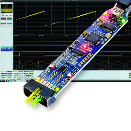
BitScope Micro is a further confirmation of the ongoing trend of making available to testers and hobbyists new devices and tools, that are more and more professional, and at always cheaper prices. The figure shows the tool with the cables supplied with the package. As for us, this is the confirmation that studying and learning is more and more suitable for everyone and for almost all budgets. BitScope Micro is the smallest in the family of products known as “USB oscilloscopes”, produced by the australian firm BitScope Designs. We focused on this specific product because it was designed to operate even with Raspberry Pi and the Micro PCs and GNU/Linux in general, as well as with normal PCs, be it with GNU/Linux or with Windows and Max/OS X. The quantity of connected cables, with relative terminals, let us think that the tool is something more than a simple oscilloscope. In fact, we are before a tool with the following features:
- Two channels oscilloscope with bandwidth of 20 MHz;
- An eight channel logic analyzer at 40 MSp;
- A real time spectrum analyzer;
- A signals generator, both analog and digital;
- All the acquired signals may be recorded to be viewed in a second time, or to be analyzed by informatic tools such a spreadsheet;
- Access APIs are available to use the tool within its own applications;
- Possibility of a “remote” visualization, on the Internet network, by means of an application “server”.
Returning to Raspberry Pi, BitScope Micro is automatically recognized as soon as it is connected to the USB port. Moderate costs, compatibly with the funtionalities of a tool of this kind, the compatibility with GNU/Linux embedded systems, the possibility of a remote management and the availability of interface APIs make it a suitable solution to be permanently installed on measurement and data acquisition systems. Since this is a measurement tool, a field test is worth more than many descriptions. Therefore, let’s install the software on our Raspberry Pi and then connect it so to use the tool. The reference website, where to download software and documentation, can be reached at the following address:
Different sections are presented in the website, one of them purposely destined to the usage of tools with Raspberry Pi. The guide for the main DSO (Digital Storage Oscilloscope) software can be found at the following address:
http://www.bitscope.com/software/dso/guide/
while the guide for the management of logic analyzers is available at the address:
http://www.bitscope.com/download/?i=182
BitScope Configuration
Let’s start with the installation of the DSO software. For this we need Raspberry Pi, with HDMI monitor, mouse and keyboard connected. The software has been produced as a desktop application with a graphic interface, and therefore it doesn’t make much sense his remote management, if not for the initial installation phase. Let’s turn on Raspberry Pi, let’s log in with the “pi” user and the “raspberry” password, and then launch the desktop application with the following command:
startx
It could be that the desktop automatically loads at the start, and we may manage this behaviour by using the function “Enable Boot to Desktop/Scratch” of the “raspi-config” tool, that we launch from a terminal window with the following command:
sudo raspi-config
if you’re logged as “root”, then “sudo” is not needed.

Let’s open the Midori web browser and go to the following address:

Let’s click on the “Download” link, in the blue rectangle up and on the right, under the big “bit Scope Pi Oscilloscope” writing.

From the download page, let’s select the following file:
bitscope-dso_2.7.EA17H_armhf.deb
or the most recent file, if present, and click on the “Download” button. In the following page, let’s click on the “Download” link and in the dialog window let’s choose to “Save”. The file will be downloaded and saved in the default “/home/pi” folder. Once the download is complete, a situation we can check by looking at the progress bar down and on the right in the page, let’s open the file manager and go to the “/home/pi” folder, that in general is already displayed as the default one.
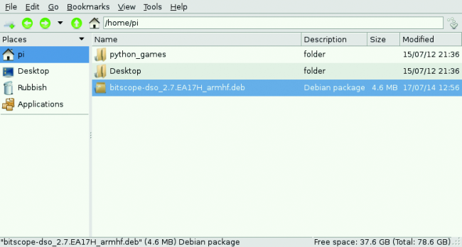
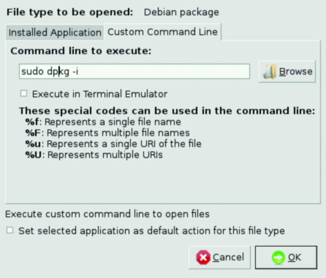
Let’s click with the right button of the mouse on the file that has just been downloaded, and in the shortcut menu, let’s choose the “Open with” option. In the second drop-down, let’s choose the “custom command line” option, and type in:
sudo dpkg -i
and let’s press the “OK ” button.
All we have to do now is to patiently wait until the end of the installation. At the end of the installation we will find the start icons for the DSO application under the voice “Other” in the “Start” menu. Let’s stop for a moment and take our small tool in hand. In the upper part, a label will summarize the main functions, with the LEDs pointing out the different operating modes of the board. On the left, there is the connector’s pins plan, to which the acquisition and/or signal generation terminals have to be connected. Many combinations are possible, as regards the acquisition of signals that can be analog, digital, originated from i2C bus, spi, can and more; and/or for the generation of analog or digital signals. 12 cables are supplied, and provided with terminal loops in different colours. At this stage, to avoid continuous plugging and unplugging of connectors, we adopted the colour plan of digital electronics, by assigning colours according to the position of the digital signals on the connector.


Let’s link the connectors with the indicated colours (or as you prefer if you want to use a different standard), and connect the BitScope USB Cable to a Raspberry Pi USB port. You may verify that the BitScope unit has been recognized by opening a terminal window and typing in the following command:
dmesg

The result can be seen in figure. Let’s launch now the BitScope DSO application.

Let’s click on the “POWER” button, up and on the right of the main application window. A window will open, allowing us to select the tool we want to manage via the application. It is possible to see that more tools can be contemporaneously used and connected, be it in “local” via USB cable, or “remotely” through the Internet network, by connecting to the IP server address to which the device is connected.
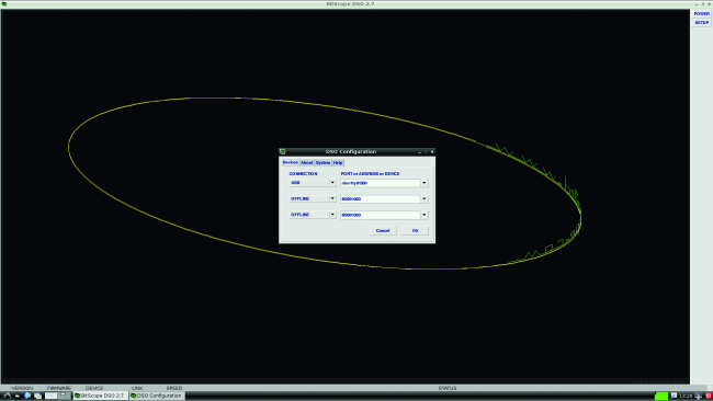
Let’s select our BitScope Micro and press the “OK” button. The management window for the tool will open. We take the opportunity to describe the different “sections” of the tool, each one indicated with a reference number:
In the main part of the screen (reference 1) the results of the measurements are shown, in a graphical form. The presented waveforms depend on the combination of choices selected with the buttons found on the right side of the page (reference 2). Up and on the left the window with the trigger settings can be seen. For the moment, let’s leave the settings of the automatic default mode.
In the manual there is the indication of how to modify the behaviour and the source of the trigger, by using the commands shown in the reference 4.

Reference 5 shows the cursor to execute accurate measurements on the diagrams presented in the main window. The controls indicated by reference 6 allow to set up the time basis so to optimise the representation of the acquired waveforms on the display, with more or less details depending on the needs. On the side, in the lower part (reference 7) there are the channel controls that can be active or not, again depending on the settings of the buttons on the right, allowing to set up the inputs, the signal sources, the representation interval, the vertical position and the scale factor. The controls indicated by reference 8 allow to configure the frequency of sample acquisition, their duration, the video refresh frequency and the representation mode.
From the store

[…] http://www.open-electronics.org/turn-your-raspberry-pi-in-an-oscilloscope-with-bitscope/ […]
[…] Turn your Raspberry PI in an Oscilloscope with BitScope […]