[youtube id=”euv3kv9kpEg” width=”620″ height=”360″]
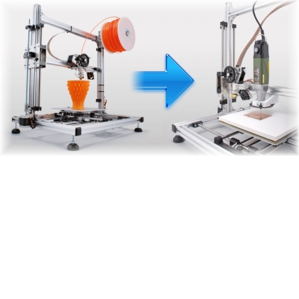
After a fair amount of work we can finally presents you a tutorial on how to modify our 3Drag printer or K8200 printer to transform it in a perfect CNC milling machine, to be used for the production of PCBs, by incision. In addition, we also show you the procedures to obtain the G-Code file required for the machine to perform the contouring of the slopes and the drilling of the base: this starting from any Gerber file or from a project made with EAGLE software.
Furthermore, to use the 3Drag as CNC milling machine you must know how to operate the printer and its management software (Repetier-Host): that’s why you should first read the articles dedicated to 3Drag.
MECHANICAL MODIFICATION TO BE MADE TO 3DRAG/K8200 TO ALLOW MOUNTING A ROTARY TOOLS
( The rotary tools can be purchased at the best hardware and DIY shops) .
The first step is to use the 3Drag to print the bracket for the mandrel whose file can be freely downloaded from the following link. The bracket , fitted out with a collar with a 20 mm hole, allows you to attach to the structure any electric-mandrel with cylindrical collar having the same diameter.
To secure other types of electric mandrels you need to change the bracket collar, creating the same kind of thread present on the power tool (by editing the skp file).
To use the 3Drag modified as CNC milling machine is necessary that the work plane is perfectly coplanar with the tool in order to obtain a uniform etching of the whole printed circuit board.
For this purpose it is necessary to carry out a particularly precise adjustment as described later . For this adjustment can also be used a comparator to be mounted on the same bracket of the power tool via an adapter printable with the same 3Drag and that, of course, will be made before you make any mechanical changes described below.
We recommend , therefore , to print one or both plastic pieces before proceeding with the printer changes.
The electric mandrel is separately powered and requires no electrical connection to the machine. The switching on and off of the tool must be done manually via the power switch supplied.
MATERIALS AND TOOLS NEEDED TO MAKE THE MECHANICAL CHANGES
To transform the printer in a CNC milling machine first of all is necessary to have the equipment, small hardware and various elements (visible in the picture), of which we give the full list.

Tools:
– Centesimal vernier caliper
– Spanner (measure 10-11 mm)
– Allen key size 4 and 5 mm
– Set square with at least 150 mm side.
Small hardware :
– 2 cylinder head screw M5 x 40
– 1 cylinder head screw M6 x 35
– 2 toothed lock washer M5
– 2 flat washer M5 x 20
– 1 flat washer M5
– 2 Flat Washer M6
– 1 self-locking nut M6 .
Miscellaneous :
– PROXXON IBS Electric mandrel / E ( or other model )
– Bracket for electric mandrel printed with the 3Drag ( with collar suitable for the power tool )
– Adapter for mounting the comparator, printed with 3Drag (optional)
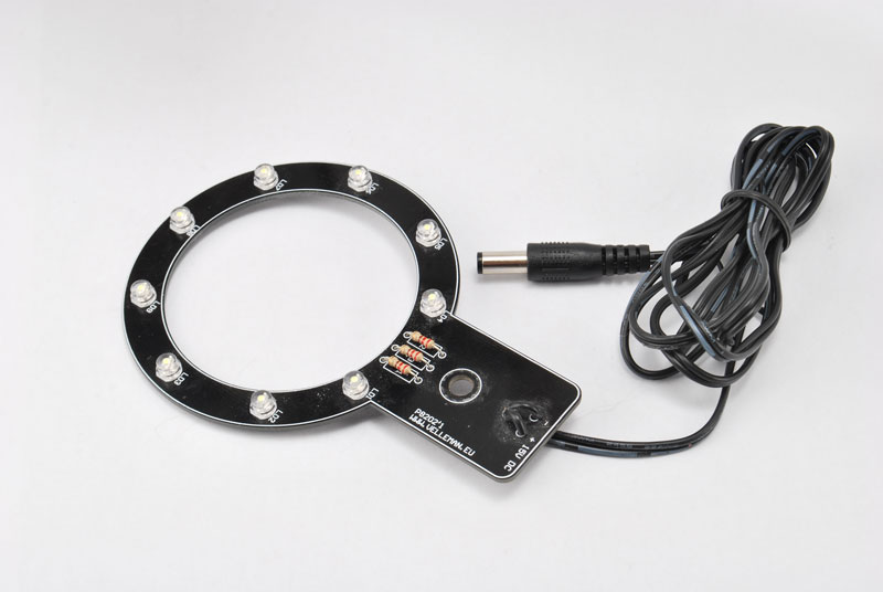
– Illuminator (optional: to illuminate the work surface you can use a common lamp)
– Square glass plate with 200 mm wide and about 3 mm thick (you can also use a standard square mirror that can be purchased from IKEA – model SöRLI )
– Square plan, 200 mm wide and 10 mm thick, made of wood ( MDF, plywood … ) or plastic ( forex , expanded polyurethane… ) with no humps , bumps or other deformations.
– Double-sided tape.
MECHANICAL CHANGES
Insert an M5 galvanized nut in the upper arm hollow taking advantage of the opening between the aluminum profile and the front plastic frame.

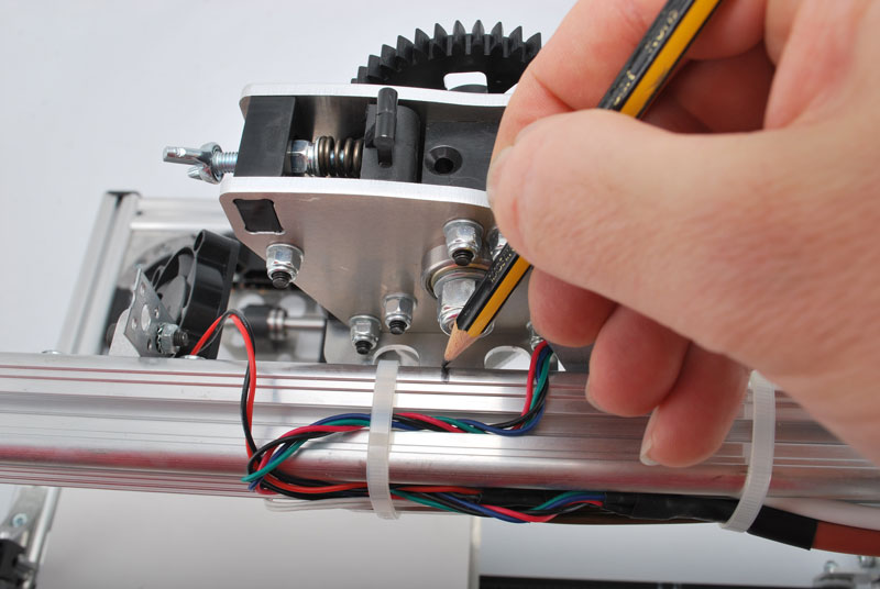
The next operation concerns the displacement of the extruder from the original position. The extruder is fixed to a bracket which, in turn, is attached to the horizontal printer arm using 2 M5 screws. Before moving, make a mark with a pencil on the printer arm at the centerline of the bracket that holds the extruder (to allow in the future to relocate the extruder in the correct position ). Cut and remove the plastic clamps that secure the wiring to the arm.
Unscrew with an allen key and remove the 2 screws that fasten the bracket to the arm.
Also loosen the two fan screws indicated by the red arrows.

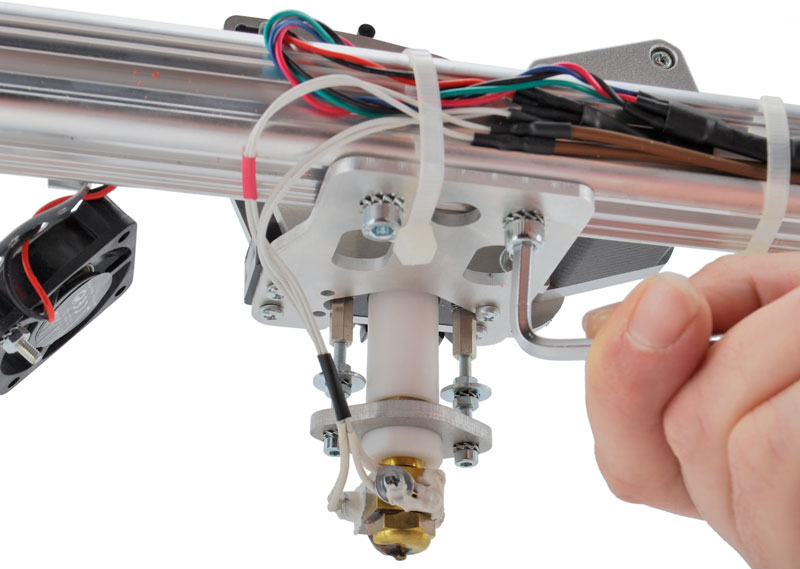
Move the extruder over the arm completely to the left (as shown in photo). Move to the same side also the fan.

In this way the nozzle of the extruder will be sufficiently separated from the work surface remaining locked to the structure.
Place, in a hole of the bracket, an M5 screw (indicated by the red arrow ) which will be screwed into the M5 nut previously inserted in the arm.

Tighten the involved screws to secure the components to the arm and reattach cables with plastic clamps .
Note: it is suggested to cover with a transparent film the entire extruder to protect it from dust which is generated during the PCB milling operations.
In the bracket front part a cylinder head screw M6 x 35 must be inserted (complete with 2 flat washers and self-locking nut M6) that will serve to tighten the collar to lock the electric mandrel.

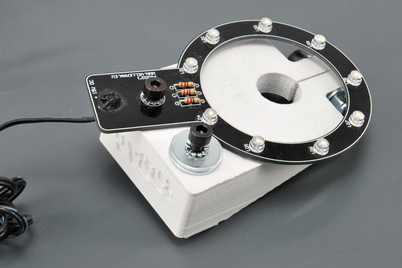
Take the illuminator (if any) and put in the only hole available a M5 x 40 screw complete with the toothed lock washer and, on the other side, with the flat washer . Note: to illuminate the work surface is also possible to use a common lamp. Re the illuminator: this element can be powered by its own power supply capable of providing an output voltage of 15 VDC or can use the same power supply of the 3Drag electronic.
Insert the fastening screw of the illuminator in one of the holes in the bracket as shown in the photo . Into the other hole insert the other M5 x 40 complete with toothed lock washer and two flat washers .
Install, under the printer arm, the bracket that will support the electric mandrel with the two cylinder head screws M5 x 40 previously inserted and bolted to the two square nuts already in the arm provided for fixing the extruder as shown in the photo below.
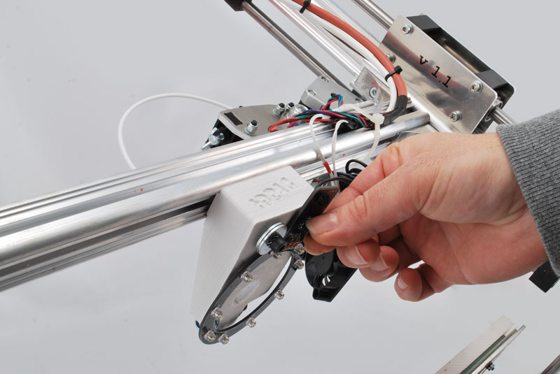
Before tightening the screws, place the bracket of the electric mandrel with the centerline moved about 1 cm to the left compared to the benchmark, reported in pencil on the arm, so that during the HOME, the position of the electric mandrel turns out external to plate , thus avoiding eventual collisions with the tool.

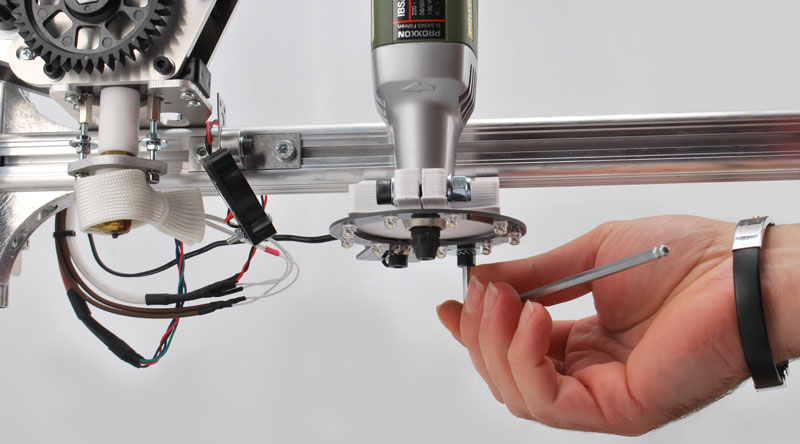
Place the power tool in the collar and , after fixing to the plastic stand, insert any bit in the mandrel and verify that, in HOME position, there is no contact between the tool and the work surface .
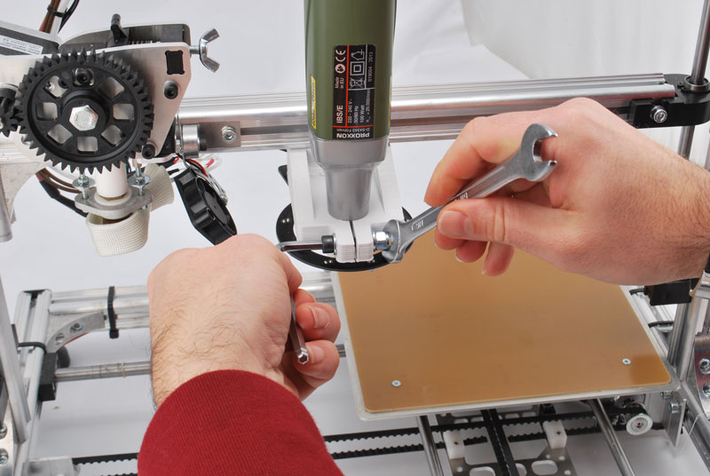
Tighten the bracket screws just enough.
Apply on the printing plate, with a little bit of double-sided adhesive, a square glass plate of 200 mm side and about 3 mm thick . Alternatively, you can also use a standard square-shaped mirror that can be purchased from IKEA
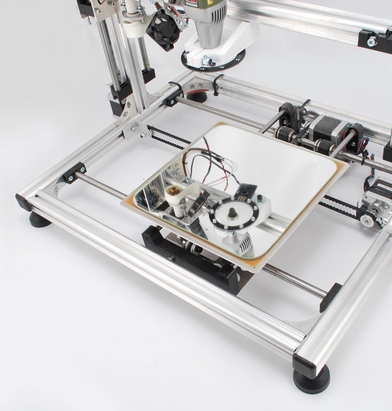
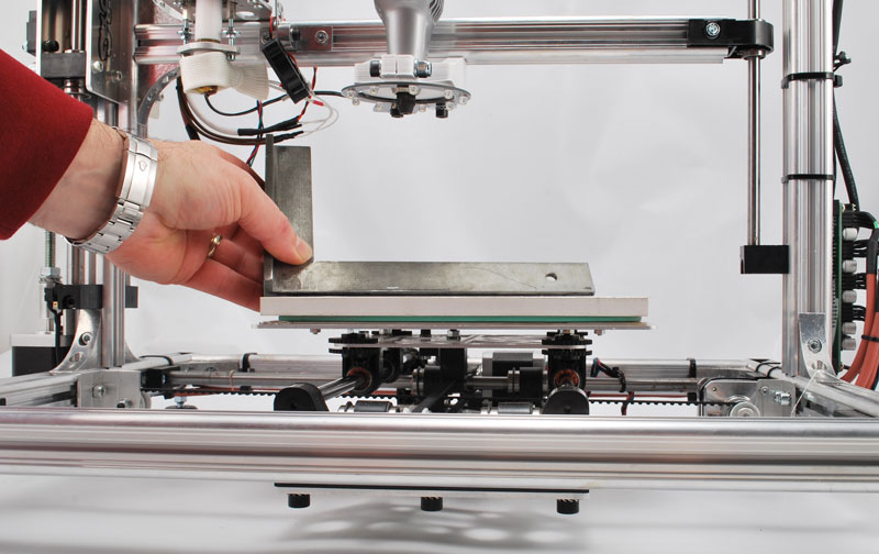
Attach to the glass / mirror a “sacrificial” plan of suitable thickness (about 1 cm ) in order to drill the holes of the PCB without damaging or breaking the tool. That plan could be MDF, forex, plywood , etc. … no humps , bumps or other deformations.
Note: the thickness must be such as to keep the PCB as raised as required to perform the processing without the Z limit switch is activated.

Tip: use a Set square or a caliper body to verify the plan regularity.
The mechanical changes to 3Drag end here. In order to use the 3Drag as CNC milling machine you must also update the firmware of the PCB printed circuit board, so that the Z axis could assume negative values respect to the position zero. To do this, download this firmware.
In the next post we describe how to create the G -code files necessary to make the printed circuits by milling .
To restore the 3D printer functionality disassemble the items described on this page and replace the extruder to its original position.

[…] How to Transform your 3Drag 3D Printer in a CNC milling machinePosted 3 weeks ago […]
[…] How to Transform your 3Drag 3D Printer in a CNC milling machinePosted 4 weeks ago […]
[…] Did you know that our 3Drag now sports CNC features? […]
[…] materials or maybe to take advantage of the mechanics of a 3D printer to create a CNC machine, as we did, or all that you mind suggests. Sharing with the others your own works will be the final […]
Why do you need a glass plate or a mirror?
To obtain a perfectly flat surface
[…] Hier der Link zur Umbauanleitung: http://www.open-electronics.org/ […]
[…] Hinweise finden sich auch auf open-electronics.org und bei Vellemann […]
[…] mit einem Direktantrieb des Extruders ausgerüstet. Der andere (baugleiche) 3D-Drucker sollte eine Option als Platinenfräse erhalten, denn die Technik-Garage möchte einen möglichst glatten Fluss ihrer Entwicklungen […]
How do I install the firmware to get my 3d printer as cnc milling router?
[…] How to Transform your 3Drag 3D Printer in a CNC milling … – After a fair amount of work we can finally presents you a tutorial on how to modify our 3Drag printer or K8200 printer to transform it in a perfect CNC milling … […]
[…] How to Transform your 3Drag 3D Printer in a CNC milling … – After a fair amount of work we can finally presents you a tutorial on how to modify our 3Drag printer or K8200 printer to transform it in a perfect CNC milling … […]