
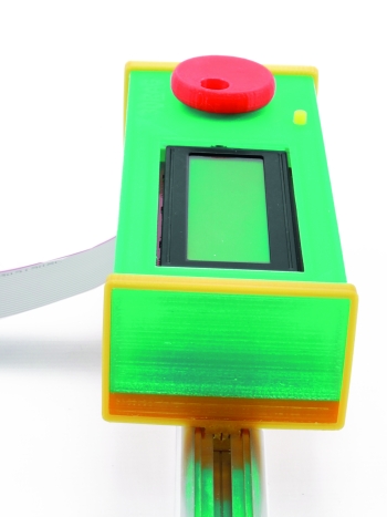
As you probably know if you have one, the overall printing quality of the 3Drag printer is very well suited for the creation of useful items: this time we have created a container for the autonomous printing system. This post, by the way, could really be a good inspiration and guideline not only for the lucky ones that have a 3Drag but, basically, for everyone having a 3d printer.
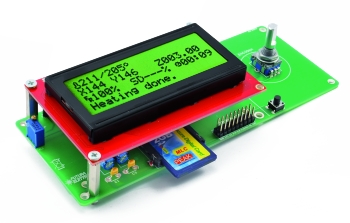
A few posts ago we indeed presented a system that complements the 3Drag controller and allows it to print G-Code files directly from the SD card thanks to an LCD display and a rotating encoder. The board was made created with the idea to enclose it in a container in mind, but, apparently, any commercial container exists that can accommodate it without having to tweak it with a series of holes and a good amount of mechanical machining. This problem is a very common one in DIY electronics history and, until accessible 3D printing debuted on the market, hobbyists used to start from the few standard case models available since the very beginning of the layout design. Not choosing a standard case, was really laborious, sometimes more than the electronic part itself.
Today, in the same way as you print pots and whistles, you can now mold containers and boxes, according to your imagination. Sites like Thingiverse are filled with models, parts and pieces, but it is almost certain that you do not find exactly what you need for your purpose.
Often, the solution then is designing your ad hoc case: it may seem complicated but, with the help of the right tools, design such kind of objects is within the reach of everyone, including beginners.
Which application?
After trying several solutions, we understood that – even with limitations and flaws – Tinkercad web is the best solution for beginners of three-dimensional modeling.
Being a web app, it works in a basically every browser with no downloads required. Models are stored directly on Tinkercad storage. Once you created your account, you will then always have both your works and the program available, regardless of the computer you will use, provided it is connected to the Internet and is also equipped with a compatible browser.
Our board case
Obviously, our post will be focused on the case we need to develop here, but we’re pretty sure that you can reuse a lot of this.
First of all we can say that the entire case (with the brackets to be fastened to 3Drag, the knob and the reset button) has been fully realized with Tinkercad, no tricks and no shortcuts. By the way, for the sake of readability, we will only focus on the implementation of part of the case – as a Tinkercad tutorial – since also the STL files are available for download and then you can download and make your case for the stand-alone printing interface for 3Drag or any RepRap printer with Sanguinololu controller.
And now .. let’s draw
 STEP 1
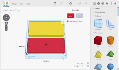
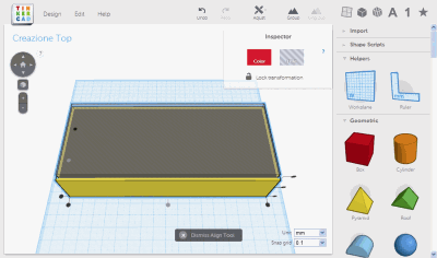
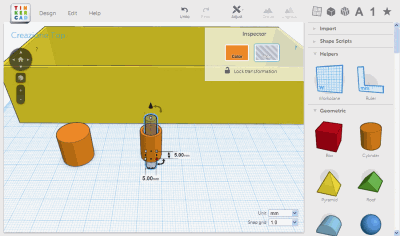
Click on New Design from your personal page, and you’ll see your empty workspace. This container should have 2 millimeters of room on the sides and the walls should be as well 2mm thick. The calculation lead us then to 168mm in width, 69mm in depth, 36mm in height and allow us to have the LCD screen approximately 1 mm back from the surface. Click on the cube in the side palette and, by holding left mouse button, drag it to the center of the work area, then pull the centered handles (the blacks squares) on the two sides of the base and bring it to measure, the square centered at the top should be used instead to change the height of our cuboid up to 36mm. By positioning on one of the handles that are white inside, on the base corners, you should read the correct measurements.
 STEP 2
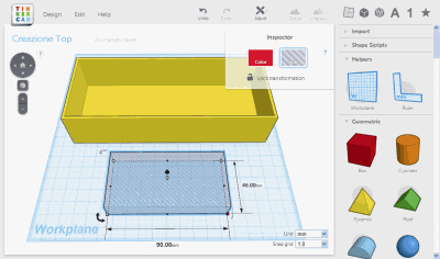
To create room inside the box use another cuboid whose measures are calculated by subtracting the thickness of the side walls, or 2 +2 mm per side. Therefore, its expected size is 164x65mm. The height of the cuboid is not however a problem, provided that it is at least equal to or greater than 36mm. Note that Tinkercad provides a 3D printer work bench and therefore we are limited to 20 x 20 centimeters. Move the two boxes to fit them on the work surface and check once again that the measurements are the exact ones for the base. Do not worry about too much about alignments at this stage.
 STEP 3
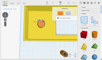
To accommodate the boxes in the correct way we use the alignment tool. First you select the smallercuboid and choose Hole in the Inspector (it becomes semi-transparent). Select both objects, and then choose Adjust -> Align to display the handles of alignment. You then choose the ones for centering – in gray in the screen – only for x and y axes. The thickness of the front of the container is managed by raising the smaller cuboid by 1.6 mm relatively to the plane. To do this you first need to select 0.1 in the bottom right of the Snap grid drop-down menu, then after selecting the internal cuboid, use the cone shaped handle that is approximately in the center of the upper face. Drag the mouse until 1.6mm value appears. Bring the Snap grid to 1.0mm, and select both objects – now lined up as required – then click Group.
 STEP 4
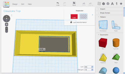
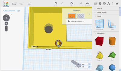
Move the top created in the previous step at the top of the working area and proceed to the creation of the “negative” box with which we will produce the LCD screen hole. The screen size is 42 x 86mm: if we create a 45 x 90mm window and we place it properly, we will be able to see the screen without having the physical contact between cover and LCD. The few millimeters left will then become a nice frame around the screen. The procedure the same: drag the cube on the floor, then tweak the size via the handles, and finally make it solid (to be subtracted) by assigning the “Hole” attribute in the Inspector. In this case the height does not matter that much (in a case of a merger with a solid, the overlapping – both full and empty part – is eliminated, while the empty excess simply disappears.
 STEP 5
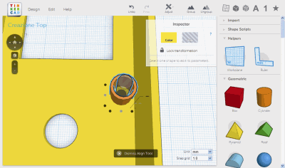
In this step, we learnt how to use the dimensioning system and movement blocker. The goal is to accurately position the hole above the display. The measures taken earlier tell us that the hole is vertically centered, while it is about 12 mm from the edge of the board. From the base outside of the container there are 3.5 mm and thus by positioning our frame 14mm from the outside of the container we will leave a couple of millimeters of room, with about half a millimeter tolerance. To place the hole properly, use the align tool and center the hole and cover on the the y axis, than use the handle that right-aligns both solids. You will then have the hole centered vertically and everything right. Now pick it and move it to the left, then press the shift key to constrain movement to one axis and stop when you read a -14mm displacement. Select the two solids and click Group.
 STEP 6
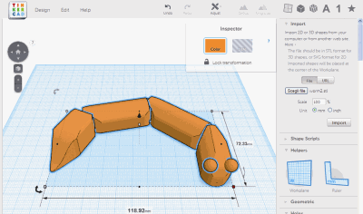
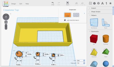
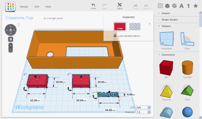
Now we need to drill two holes for the handle and the reset button. The hole of the knob is 15mm, while for the reset we create a void cylinder that will serve as a guide for a piston (with two different diameters).
In the picture you can see the three-cylinder engine that you create in this step: the height of the 15mm one does not matter (it will be a hole), while the one with the 10mm diameter should be 18mm high. His 8mm hole, of course, should be at least 18mm long to be able to pass through it once combined. To understand better the mechanism: consider that the hole on the front that we will create will be aligned with the reset button which, however, is only 5mm tall (we still lack 30mm, and we will need something that sticks out that you can press). Creating a 35mm tall cylinder we can get to the button, but keeping everything aligned would be very difficult: that’s why we create the the hollow cylinder in which the piston slides. To prevent the piston to come out, we’ll create it 7mm in diameter at the bottom and 4 mm in the upper half.
 STEP 7
To reach the results you see here, you must assign Hole to the 8mm cylinder, then align it with the 10mm cylinder in the center and group them. The result will be the empty cylinder with 1mm walls to be placed in the inner part of the lid of the container. At this point we still lacks the cylinder with which to make the hole in the front panel. This must be 5mm so that the 4mm piston has a good chance to go through it at the first shot, otherwise you will have to give the finished print a rasp shot to remove the excess material. Unfortunately, you can not group a solid with an Hole keeping the negative volume: only the “full” part remains. To create the cylinder and the hole then we will have to keep them apart, place the first and then align the second. At this stage we can just plunge a little the ‘”hole” to make the hole visible from underneath.
 STEP 8
The hole of the encoder knob also needs to be carefully positioned, even if the knob covers the hole underneath hiding small misalignments. Again we took the measures and we know that the encoder pin is vertically centered and about 26mm from the edge of the print. Let’s add 2mm for the border, 2mm wall thickness and subtract 7.5 mm to base the procedure on the edge of the cylinder and not on its center. We get 22.5 mm (round up to 23mm), this is the distance which the edge of the cylinder must have from the left wall. As we did for the LCD screen hole, we start by selecting the cover and cylinder, then we align it left and vertically and at the center. Select the cylinder only and using the shift, block Y axis (it’s only movable on X): drag it to the right until you read 23mm: now you can assign the Hole material to the cylinder and, if you will, Group it with the cover.
 STEP 9
Positioning the cylinder that houses the reset button piston requires a little attention, but it allows us to experience how Tinkercad makes even precision operations easy. The system is based on simple principles: alignment and shift offsets relative to a starting point. If, while moving, you leave the mouse button, the starting point becomes the one where you inadvertently dropped the object, and then you must start over. The Undo button, in this case, it is more useful than ever. In the screen on the right you see how the hollow cylinder should be positioned: 42mm from the left edge and 3mm from the bottom. Just 1mm space between the wall and the cylinder should be left. To be noted that we left the hole in its previous position. The procedure is the same just used: Align command is used to bring the cylinder to the bottom left of the cover and then move it up to the right heights.
 STEP 10
Now we must make a 5mm hole in the front in correspondence with the cylinder guide that is already in its proper position. That’s left to do then is to align the hole in the center of the cylinder guide. If you click on the handles of the Align function you’ll see that there is no object that keeps staying between the two to align, and then if you don’t put severe attention to alignments, you are likely to move the wrong solid.
The rectangle that shows up between the two selected objects (for the alignment) shows where the objects are supposed to land in the case of outer side alignment (when centering instead both objects are moved, unless one is within the other). In our case, therefore, first move the hole inside the cylinder and Align after: in this way the guide cylinder does not move and the hole can be centered without any problem. Once centering is done, you can select hole, cylinder, lid and Group it.
 STEP 11
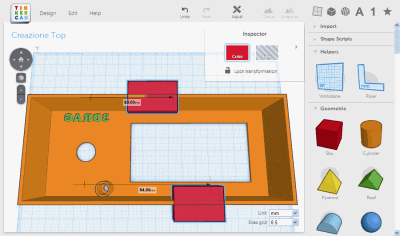
holes on the front are now all in place and we can move on to the preparation of the two slots with which to insert the SD card and pull out the ribbon cable to the controller. To simplify the assembly and have a good result, we will create holes that reach the edge of the wall. The memory card needs at least 25 mm, while the 20-lead flat cable is 26mm wide. Add some ‘of ease on both sides and we get 32mm to 30mm and the flat cable to the SD card. The thickness of the wide box 32 must be 9mm, while that from 30 must be 4mm thick. While we’re at, we also create a written 3DRAG to be placed on the panel, above the encoder knob. Take from the palette on the right letters and compose the message, leaving the letters a bit ‘spaced, then group them and bring them to the size you see in the picture. With the handle for rotation relative to the axis Y overturned the written so that both the mirror.
 STEP 12
To place the two holes in their right places, we once again use the relative offsets from the edges of the print. The cable is almost aligned with the left side of the LCD screen, while the slot for the SD memory card is positioned at its center. Transforming this into offsets, the 30mm hole should be 65mm away from the left side while the one for the memory card must be 94mm away, always from the edge. Alignment to the left and to the top so that the holes create a slit up to the top edge, interrupting it. Alignment and the y-axis size of these two cuboids is not important since they will be subtracted from the walls.
In this phase we also put the 3DRAG label above the knob, towards the upper edge. Allow about 3mm between the label and the inside of the cover, remember that the knob is 38mm in diameter and then it exceeds center of the hole by 19mm. If the label is too low, is covered by the knob.
 STEP 13
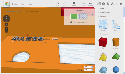
Now is the time to take care of the 3Drag label just created. We wanted to create something different but still easy to print was to create a groove with the inscription on the front panel while not piercing it (otherwise some parts of the letters could not exist, such as in D or A). If we had gone from the outside in of the lid, the printer would have to “close” the fonts from the above since the outer part would be in touch with the printing plate. We instead raised the label by a couple of layers of printing so that the transparency of the layers would allow us to see it. To raise the label up, change Snap grid and then lift the cone handle, highlighted in red in the image. Also check that the writing is substantially horizontally centered with respect to the hole of the knob.
STEP 14
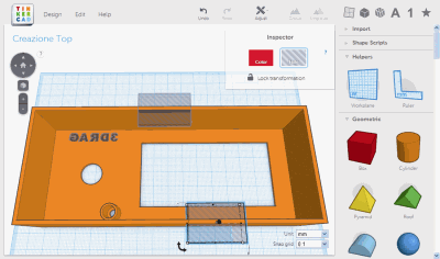
We’re almost done: we just need to incorporate the last “voids” in the structure of the cover. Click on each of the pieces and assigned “Hole” color fromte Inspector, and then select the cover and the pieces and Group them: this will integrate the voids in the model. With the mouse you can now inspect the final result and see how the Align function grants perfect “cuts” between full and empty zones, which is not always the case with CAD applications. To see the front of the container, just move the point of view under the work plan that has a partial transparency.
 STEP 15
Now the work is really done: the creation stays on the floor with the front of the cover, and this allows a very simple print that with no particular inclinations or undercuts. The only difficulty may be the fairly extensive surface and therefore potentially subject to detachment from the plate. Click on Design and choose Download for 3D print to display the window that shows you the various formats. Select STL and then prepare the printer for this new job. Download the other elements of our stand-alone printing container from our website or from Tinkercad. For trouble-free printing, we suggest you to print two or three reset buttons: The terminal 4mm part is too small to be printed by itself without deformation, while if the printing is done with two or three buttons, the plastic is able to cool off and keep the shape.

[…] How to design and 3D print a case for an electronic board, from OpenElectronics: […]
This is just a translation of a story written by Simone Majocchi. Credit should be given to him, He is the author of the whole project on Tinkercad, not Boris Landoni.
Thanks for the correction on the attribution,