- Building a 3D Digital Clock with ArduinoPosted 4 months ago
- Creating a controller for Minecraft with realistic body movements using ArduinoPosted 5 months ago
- Snowflake with ArduinoPosted 5 months ago
- Holographic Christmas TreePosted 6 months ago
- Segstick: Build Your Own Self-Balancing Vehicle in Just 2 Days with ArduinoPosted 6 months ago
- ZSWatch: An Open-Source Smartwatch Project Based on the Zephyr Operating SystemPosted 7 months ago
- What is IoT and which devices to usePosted 7 months ago
- Maker Faire Rome Unveils Thrilling “Padel Smash Future” Pavilion for Sports EnthusiastsPosted 8 months ago
- Make your curtains smartPosted 8 months ago
- Configuring an ESP8266 for Battery PowerPosted 8 months ago
Hack your Valentine with HeartThrob
Today we present the perfect Valentine gadget: just shake it and it will turn on and crate incredible light animations. That will be cool for sure!
We know that, as it’s Valentine’s Day, looking at the device described in this post you’ll be inclined to think that this is the usual heart-shaped Valentine gadget: in reality this is something much cooler as it’s capable to create beautiful and complex light games. Is based on the smallest microcontroller manufactured by Atmel: the ATtiny85.
We selected the microcontroller according to precise criteria: we needed a compact controller, easy to program and with an excellent performance in terms of energy consumption. The ATtiny is an 8-bit micro that has 8 kB of memory, six lines of I / O (note that they are exactly as many as needed for the project, given that it is better not to use the dedicated reset pin), four 10-bit ADC channels and this can arrive, with the use of an external quartz, at a working frequency of 20 MHz, although in our project we stuck of the 8 MHz internal oscillator. Everything compacted in a DIP format in an eight-pin TSSOP case.
A special feature of the micro is that the firmware can be written using the Arduino IDE and programming language, loading the program in ‘ATtiny85 using the handy ICSP pin found in the most common Arduino boards, that we have provided with the same layout even in the back of the PCB to facilitate the connection.
As a last, but not least, characteristic the little Atmel controller, can be both powered from the USB or ICSP bus (ie 5V), or from the LiPo 3.7V 500mAh battery, depending on the position of the switch slide, thanks to its range of operation that ranges from 3.5 V up to 5.5 V. Using the sleep mode, the system has a long battery life: activating this mode, you get to consume only 2 μA.
Circuit diagram

The circuit, which is heart shaped, consists of 32 high-brightness LEDs placed on the board, lit by the microcontroller. Since the latter does not have all the I / O you need, we interfaced with a TLC5940, which is a twenty-eight pin integrated by Texas Instruments, designed specifically for controlling the brightness of each LED. The component has sixteen 12 bits PWM driver equipped channels and 6-bit correction current; each channel is independent and the intensity of the light emitted by the LED connected to the driver depends on the average value of the PWM signal: having available 12 bits for the control of such a signal, it is clear that between LED off (duty cycle = 0%) to LED on (duty cycle = 100%) we will have 4,096 levels of brightness. The 6 bits for brightness correction allow 64 levels. You can however set the maximum current absorbed (in fact this driver only controls the flow of current to ground) from all channels of the IC via pin 20, namely IREF, which must be connected to a resistor.
Regarding the communication with the controller, the TLC5940 has a serial input SIN, the signal pins XLAT, multifunction pin VPRG, the data pins DCPRG, the serial clock pin SCLK, clock pin for the PWM signal GSCLK and the reset pin at a low level of all outputs, BLANK. A very interesting feature of this integrated is the ability to daisy-chain multiple devices to each other by simply bringing the serial output pin SOUT SIN pin of the previous device to the next one and connecting in parallel all the other pins of the data in order to manage several integrated with just one controller.

At this point one must question: how does the TLC590 (with just sixteen outputs) control 32 LEDs? Ideally, we would have to use two TLC590, but this would have resulted in the doubling of consumption (at the expense of the autonomy of the device) and footprint. That’s why we found an alternative, which is to multiplex the outputs. The multiplex is obtained via a single pin of the controller that controls the PNP transistor type BC327-25. The output pin of the controller is connected to the bases of T1 and T3 transistors, of course using the appropriate resistors R7 and R9, respectively. In turn, the collector of the transistor T1 is connected to the base of transistor T2 and to ground via the R6 resistor so as to act as a NOT logic gate for T3. Finally, T2 collector is connected to the anode of the odd LED while the collector of T3 to the anode of the equal LED (the numbering of the LEDs, starts at the lower part of the heart and continues counterclockwise, following the outputs of the TLC5940). The cathodes of the LEDs, however, are connected two by two in such a way that follows and, in turn, to the outputs of the driver.
To allow the circuit to respond to an external stimulus; the S1 switch is used. Inside it there is a small metal ball that, when you shake the component, connects the central rheofore with the outer casing resulting in the closure of the contacts (casing and the center pin) . The pin of the microcontroller that reads the sensor has been fitted with pull-up resistor (20 kΩ) since otherwise when the contact is open (at rest) the same leg would be exposed to noise being prone to false alarms.

Once finished analysis of the control block, let’s now look at the description of the power supply section: the circuit consumes an average of 55 mAh. This energy can come in continuously from the USB bus-type mini-b that is on the back of the board connected to an external source, or from a single-cell 3.7V- 500 mAh LiPo battery. The switch SW1 helps to setup the power spurce: if the cursor is moved to the battery, the device is running on battery power, if it is moved to the USB connector, the circuit is switched off when on battery power, switched on and in charge if powered via USB, and finally turned on and in charge and programmable if powered by ICSP pins.
Regarding charging the battery, it was necessary to use a special component built specifically for this purpose: the MCP73831. This integrated is manufactured by Microchip, available in a SOT-23 SMD 5-pin case and is a one cell to 3.7 V LiPo batteries charging manager. To check the status of the charging process of the battery, LD33 LED (red, it indicates that the battery is charging) and LD34 (yellow, indicates that the battery has finished charging) have been used. The MCP73831 has five operating modes that allow you to preserve battery capacity after repeated charge cycles.
-
SHUTDOWN MODE: The controller is not charging the battery and the output STAT is in high impedance state (LED LD33 and LD34 lit), this state occurs if the power supply VDD is lower than the voltage VBATT of the battery or of the threshold voltage VUVLO the Under Voltage Lock Out voltage. The UVLO is a special circuit protection which disables the MCP73831 in case the voltage supply falls below a preset threshold. The controller can be found at rest even if the resistance RPROG, which serves to define the charging current of the battery, has a value greater than 200kΩ.
-
Preconditioning MODE: the controller checks the battery voltage. If the latter is greater than the threshold voltage VPTH, the controller switches to the next stage, otherwise it starts to charge the battery with constant current IPREG until VBATT does not exceed VPTH. This is to preserve the battery capacity. The STAT output is low ie the LD33 LED is lit.
-
FAST CHARGE MODE: The controller charges the battery with constant current IREG until the voltage of it reaches the value of the VREG output.. The value of IREG can be set via the resistor external RPROG connected to the PROG pin of the controller, according to the formula IREG=1,000 v / RPROG. In our case a RPROG of 2kΩ applies, then the current is 500 mA (the maximum payable from the integrated) . For this it was necessary, as indicated in the datasheet, to create plots of heat dissipation. The output STAT is maintained at low level.
-
CONSTANT VOLTAGE MODE: In this phase, the controller charges the battery with constant VREG until the current reaches the value I.TERM . STAT output is maintained at a low level.
-
CHARGE COMPLETE MODE: This is the final stage of the charge. The controller returns to the idle state and the output STAT goes high to turn on the yellow LED LD34.
With the 500 mAh battery 90 minutes are required for a full charge which will provides 9 hours of operation with LEDs on or 50 hours in sleep mode.

BOM
R1: 2 kohm
R2: 220 ohm
R3: 220 ohm
R4: 2 kohm
R5: 10 kohm
R6: 1 kohm
R7: 10 kohm
R8: 10 kohm
R9: 1 kohm
C1: 100 nF 100 VL
C2: 100 nF 100 VL
U1: ATTINY85
U2: TLC5940
U3: MCP73831
T1: BC327-25
T2: BC327-25
T3: BC327-25
LD1÷LD32: LED 5 mm red
LD33: LED 3 mm red
LD34: LED 3 mm yellow
SW1: switch
S1: Vibration switch
The sketch
Let’s now look in detail the core part of the project, the firmware to be loaded into the microcontroller. To better understand the code, let’s examine, first, the flow chart of the processes that the ATtiny must play. The first block “systemin itialization” pertains to the classic operations that take place at power up, such as to initialize the inputs and outputs, the storage space and other operations for which you do not need to say too much. After that, the system waits two seconds to prevent vibrations start immediately to light up leds.
The following block is very important because it determines the whole structure of the code that we will see later, it is critical to power-saving mode, more properly called sleep. This particular condition is used to stop the CPU clock and the other integrated peripherals, which implies that the program is paused until the microcontroller does not wake up. So the problem becomes how to awaken our ATtiny: to solve it, just look to what devices are still active in Table1 taken from the datasheet of the ATtiny85.
 Here we’ll see the characteristics of the three possible sleep modes. As for us, we will use the last one as is the one allowing you to consume less power, about 2 uA. For the awakening we do not have many options, but there is one that is just right for us, By using a Change Interrupt Pin (PCINT) input which is connected to the vibration switch we will be able to wake up the microcontroller in case of vibration. Look back to the flow chart to just see that particular in the next step: the system waits sleeping for a vibration to wake it up and continue the execution of the program. Once awakened it stops the power-saving mode and reactivates the modules and functionality you need to work properly.
Once awakened it will assess whether the vibrations are just episodic and, in this case, will turn on the LEDs with a random sequence among those available and then restart the cycle back into power saving mode.
Having said that let’s see how these works into actual Arduino IDE code. At first you’ll notice the definition of some parameters that we will see how to set later in the configuration, as they are empirical values.
Afterwards you’ll move on to the include section of the necessary libraries.
-
The Sleep library which provides methods to manage the sleep mode and its awakening. This library is part of the standard libraries for Arduino: more precisely is included in the AVR library package.
-
The Power library, allows you to turn on and off some of our microcontroller modules with very simple and practical methods. Like the Sleep library, this is part of the AVR package. In particular, we note that these two libraries go hand in hand as they deal with similar issues. The substantial difference lies in the fact that Power acts on CPU’s peripheral modules, while Sleep works directly on the CPU.
-
The PinChangeInterrupt library which is specific for ATtiny greatly simplifies the management of PCInt. This library is not present by default in the Arduino IDE and we will see later, in the part dealing with programming, where you can find it and how to included it between your libraries.
-
The Tiny85_TLC5940 library is tailor-made for the ATtiny85 and allows you to control one or more TLC5940 by using only 3 pins of the microcontroller. Clearly this leads to a reduced ability to exploit the potential of our LED drivers, but for what we need for this project we can settle quietly. Neither this library is present by default in the Arduino IDE. As for the PinChangeInterrupt we’ll be back on this later.
The “set_sleep_mode (SLEEP_MODE_PWR_DOWN)” method pertains to the Sleep library that is used to set which of the sleep modes available (see Table ) you want to use. Be careful to make just one choice.
Then a bit ‘special passage: disabling the ADC module and shutting it down.These two operations are not equivalent and this module needs to be disabled first and then be shut down.
Entering the loop we find the sleepNow routine in which our microcontroller makes a series of steps to entering sleep mode:
-
Set pin 3, used for the transistors polarization, as input and enable the relative pull-up resistance. This little trick allows you to deliver less current from the pin and only polarize the T2 transistor.
-
Reset the communication with the TLC5940 and turn off all its outputs using “tlc5940.init()”
-
Disable TIMER0, TIMER1 and USI modules by using “power_timer0_disable(); power_timer1_disable(); power_usi_disable();” This allows to further reduce the consumption of the micro.
-
Set a pin change interrupt on pin 4 (that of the vibration switch) by using “attachPcInterrupt(4, WakeUp, CHANGE)”. In particular, with this method, we make sure that the microcontroller executes the ISR “WakeUp” whenever there is a change of state on pin 4. We will use this feature to awake the ATtiny85. The WakeUp routine could also be empty, but in our case we added a function that increments the variable beat counter: this will allow us to empirically evaluate the intensity of the vibration.
Now our small microcontroller is ready to sleep: by using the sleep_mode () method it will go into the sleep mode previously selected. The CPU will remain stuck at this stage of the program sketch until a vibration will awake it again.
Let’s suppose the PCInt will awake the CPU: continuing with the description of the code following the logical order, you’ll find “sleep_disable()”and “power_timer1_enable ()”, two methods that are used to bring the microcontroller back to operating. More precisely, the first is used to restart the CPU and exit from sleep mode, while the latter is to re-enable the TIMER1 we need to be able to use the functions like millis and micros.

After recovering, the microcontroller, checks if the awakening vibration is strong enough (according to the parameters set at the beginning). If this is not the case, the ATtiny85 will restart the loop and return to sleep mode. If the vibration is strong enough, the micro will execute the lighteffect routine that has the purpose of starting a luminous effect on the LEDs, first disabling the interrupt preventing subsequent disorders in the processes. Must then re-enable the TIMER0 and USI modules that serve for the communication with the TLC5940 and that were disabled before. You also need to reset the 3 pin as output.
Once all this is done, the heart is ready to lit up: it just needs to choose a random function among those scheduled. To do so and the micro uses a pseudo-random calculation, using the random functions and micros. The result of this operation is used in a switch that determines which routine to execute. Note that with this method a function can never be repeated twice in a row. Let us now consider one possible routine to understand the principle of operation used. For example, let’s take into account the throb function that is programmed to emulate an heartbeat. First, we see that there is a while loop that is executed repeatedly for a time at least equal to the DURATION parameter set at the beginning of the code. Secondly, you can see that the data in the array values is changed. These represents the level of brightness of each single LED from 0 to 4095, where 0 stands for switched off and 4095 for switched on. We see then that we enter into another routine called heartUpdate, which has the actual purpose of sending data to the LED drivers and of lighting them up by polarizing the transistors. Looking at the code in this method, we note that the input parameter time is used to quantify the milliseconds in which the process contained in the do-while loop will be repeatedly executed. Within this cycle there are two almost equal parts of the code in which you enable the odd or even LEDs intermittently and, in the meantime, you turn on the TLC5940 outputs using the methods of the related library
-
“tlc5940.set(i, values [i * 2])” is used to set the value of each output by taking the values from the array values, but not sending them
-
“tlc5940.update ()”used to send the data to our LED driver.
This latter method is kinda special because It takes about one millisecond to run and only during this period TCL5940 outputs are activated, which inducts the need to perform this method as frequently as possible, without using any delay because it would mean to take off the LED for that amount of time. All these problems are caused by the fact that the ATtiny85 does not have enough capabilities to better communicate with this LED driver.
Finally, the routine ends using the same principles already explained and then it resumes the loop by sending the microcontroller back into sleep mode.
Code
#define DURATION 45000            //Durata effetto luminoso (ms)
#define I_VIBRATION 7             //Soglia intensità della vibrazione
#define D_VIBRATION 10            //Durata periodo di campionamento
                                  //per quantificare l'intensità della vibrazione
#define NUMBER_OF_FUNCTIONS 8     //Numero di funzioni programmate

#include <avr/sleep.h>
#include <avr/power.h>
#include <PinChangeInterrupt.h>
#include <Tiny85_TLC5940.h>

unsigned int values[32] = {0};//Array contenente lo stato dei 32 LED
byte f;                       //Variabile per scelta di funzione
volatile byte beatCounter=0;  //Variabile per quantificare l'intensità della vibrazione

void setup() {
  pinMode(0,OUTPUT);      //Pin per la comunicazione con il TLC5940 impostato come output
  pinMode(1,OUTPUT);      //Pin per la comunicazione con il TLC5940 impostato come output
  pinMode(2,OUTPUT);      //Pin per la comunicazione con il TLC5940 impostato come output
  pinMode(3,OUTPUT);      //Pin che gestisce i transistor impostato come output
  pinMode(4,INPUT);       //Pin dell'interruttore a vibrazione impostato come input
  digitalWrite(4,HIGH);   //Abilitazione resistenza di Pull-Up sul pin 4

  tlc5940.init();                       //Inizializzazione comunicazione col TLC5940
  set_sleep_mode(SLEEP_MODE_PWR_DOWN);  //Impostazione della modalità Sleep
  ADCSRA &= ~(1 << ADEN);               //Disattivazione del modulo ADC
  power_adc_disable();                  //Spegnimento del modulo ADC

  delay(2000);                          //Aspetta 2s
}

void loop() {
  sleepNow();                           //Funzione per abilitare la modalità sleep
  //Attesa di una vibrazione
  sleep_disable();                      //Fine modalità sleep
  power_timer1_enable();                //Abilitazione Timer 1

  beatCounter = 0;
  unsigned long t=millis();

  while(millis() - t < D_VIBRATION)     //Quantificazione dell'intensità della vibrazione
    if(beatCounter >= I_VIBRATION)      //Se è maggiore della soglia
      lightEffect();                    //Fa partire gli effetti luminosi
}

void sleepNow() {
  pinMode(3,INPUT);                     //Pin che gestisce i transistor impostato come input
  digitalWrite(3,HIGH);                 //Abilitazione resistenza di Pull-Up sul pin 3

  tlc5940.init();                       //Resetta comunicazione col TLC5940

  power_timer0_disable();               //Spegnimento del Timer 0
  power_timer1_disable();               //Spegnimento del Timer 1
  power_usi_disable();                  //Spegnimento del modulo USI

  attachPcInterrupt(4, wakeUp, CHANGE); //Impostazione interrupt sul pin 4

  sleep_mode();                         //Inizio modalità sleep
}

void wakeUp() {  //Funzione attaccata all'interrupt
  beatCounter++;
}

void lightEffect() {
  detachPcInterrupt(4);   //Disabilitazione dell'interrupt

  power_timer0_enable();  //Abilitazione il Timer 0
  power_usi_enable();     //Abilitazione il modulo USI

  pinMode(3,OUTPUT);      //Pin che gestisce i transistor impostato come output

  for(byte i=0;i<32;i++)  //Azzeramento dei dati dell'array
    values[i]=0;

  //Calcola una funzione a caso da eseguire
  f = (f+1+(micros()+random(NUMBER_OF_FUNCTIONS))%(NUMBER_OF_FUNCTIONS-2))%NUMBER_OF_FUNCTIONS;

  switch(f){              //Esegue la funzione scelta
    case 0:
      throb();
      break;

    case 1:
      runningLeds();
      break;

    case 2:
      randomFade_1();
      break;

    case 3:
      randomFade_2();
      break;

    case 4:
      runningFade();
      break;

    case 5:
      sequence_1();
      break;

    case 6:
      sequence_2();
      break;

    case 7:
      sequence_3();
      break;

    default:
      break;
  }
}

void heartUpdate (unsigned int time) {
  const unsigned long startTime = millis();

  do {
    digitalWrite(3, 0);              //Abilitazione dei LED "pari"

    for(byte i=0; i<16; i++)
      tlc5940.set(i, values[i*2]);   //Impostazione del valore dei LED

    tlc5940.update();                //Invio dati al TLC5940

    digitalWrite(3, 1);              //Abilitazione dei LED "dispari"

    for(byte i=0; i<16; i++)
      tlc5940.set(i, values[i*2+1]); //Impostazione del valore dei LED

    tlc5940.update();                //Invio dati al TLC5940

  } while (millis() - startTime <= time); //Ripeti il processo per un numero di ms
                                          //maggiore o uguale a quello del parametro "time"
}

//Funzioni per gestire le sequenze luminose dei LED:

void throb() {
  const unsigned long startTime = millis();

  while (millis() - startTime <= DURATION) {
    for(char v=0; v<=117; v++) {
      for(byte j=0; j<32; j++)
        values[j] = v*35;

      heartUpdate(1);
    }
    heartUpdate(50);

    for(char v=117; v>=0; v--) {
      for(byte j=0; j<32; j++)
        values[j] = v*35;

      heartUpdate(10-v/13);
    }
    heartUpdate(50);
  }
}

void runningLeds() {
  const unsigned long startTime = millis();
  const byte v[4] = {39,5,0,5};
  byte i;
  for(byte k=1; k<6; k++){
    while (millis() - startTime <= k*(DURATION/6)) {
      i = (i-1)%4;

      for(byte j=0; j<16; j++)
        values[j] = values[j==0?16:(32-j)] = v[(j+i)%4]*105;

      heartUpdate(80);
    }
    k++;
    while (millis() - startTime <= k*(DURATION/6)) {
      i = (i+1)%4;

      for(byte j=0; j<16; j++)
        values[j] = values[j==0?16:(32-j)] = v[(j+i)%4]*105;

      heartUpdate(80);
    }
  }
}

void randomFade_1() {
  const unsigned long startTime = millis();
  byte c = 0, i = 0, end=6;

  while (millis() - startTime <= DURATION) {
    for(byte j=0; j<32; j++)
      values[j] = 0;

    i = end-6;
    i = (i+1+(micros()+random(16))%14)%16;
    end = i+6;

    c++;

    for(unsigned int k=0; k<4096; k+=13){
      for(i=end-6; i<=end; i++)
        for(byte j=0; j<16; j++)
          if(j == i%16)
            values[j] = values[j+16] = k/(1+abs(end-i-3)*3);
      heartUpdate(1);
    }

    for(unsigned int k=4095; k!=0; k-=13){
      for(i=end-6; i<=end; i++)
        for(byte j=0; j<16; j++)
          if(j == i%16)
            values[j] = values[j+16] = k/(1+abs(end-i-3)*3);
      heartUpdate(1);
    }
  }
}

void randomFade_2() {
  const unsigned long startTime = millis();
  byte c=0, i=0, end=6;

  while (millis() - startTime <= DURATION) {
    for(byte j=0; j<32; j++)
      values[j] = 0;

    i = end-6;
    i = (i+1+(micros()+random(8))%6)%8;
    end = i+6;

    c++;

    for(unsigned int k = 0; k < 4096; k += 13){
      for(i=end-6; i<=end; i++)
        for(byte j=0; j<8; j++)
          if(j == i%8)
            values[j] = values[j+8]= values[j+16]= values[j+24] = k/(1+abs(end-i-3)*3);
      heartUpdate(1);
    }

    for(unsigned int k=4095; k!=0; k-=13){
      for(i=end-6; i<=end; i++)
        for(byte j=0; j<8; j++)
          if(j == i%8)
            values[j] = values[j+8]= values[j+16]= values[j+24] = k/(1+abs(end-i-3)*3);
      heartUpdate(1);
    }
  }
}

void runningFade() {
  const unsigned long startTime = millis();
  for(byte i=0; i<32; i++)
    values[i] = ((i%8 == 0) || ((i+1)%8 == 0)) ? 4095 : 0;

  byte j=0;
  for(byte k=1; k<4; k++){
    while (millis() - startTime <= k*(DURATION/4)) {
      for(unsigned int v=0; v<=455; v++) {
        values[j==0?31:j-1] = values[j+7] = values[j+15] = values[j+23] = 4095-v*9;
        values[j+1] = values[j+9] = values[j+17] = values[(j+25)%32] = v*9;

        heartUpdate(1);
      }
      j = j==7?0:j+1;
    }

    k++;
    j = j==0?7:j-1;

    while (millis() - startTime <= k*(DURATION/4)) {
      for(unsigned int v=0; v<=455; v++) {
        values[j==0?31:j-1] = values[j+7] = values[j+15] = values[j+23] = v*9;
        values[j+1] = values[j+9] = values[j+17] = values[(j+25)%32] = 4095-v*9;

        heartUpdate(1);
      }
      j = j==0?7:j-1;
    }

    j = j==7?0:j+1;
  }
}

void sequence_1() {
  const unsigned long startTime = millis();
  for(byte i=0; i<32; i++)
    values[i] = ((i%8 == 0) || ((i+1)%8 == 0)) ? 4095 : 0;

  byte j=0;
  for(byte k=1; k<4; k++){
    while (millis() - startTime <= k*(DURATION/4)) {
      for(unsigned int v=0; v<=455; v++) {
        values[j==0?31:j-1] = values[j+7] = values[j+15] = values[j+23] = 4095-v*9;
        values[j+1] = values[j+9] = values[j+17] = values[(j+25)%32] = v*9;

        heartUpdate(1);
      }
      j = j==7?0:j+1;
    }

    k++;
    j = j==0?7:j-1;

    while (millis() - startTime <= k*(DURATION/4)) {
      for(unsigned int v=0; v<=455; v++) {
        values[j==0?31:j-1] = values[j+7] = values[j+15] = values[j+23] = v*9;
        values[j+1] = values[j+9] = values[j+17] = values[(j+25)%32] = 4095-v*9;

        heartUpdate(1);
      }
      j = j==0?7:j-1;
    }

    j = j==7?0:j+1;
  }
}

void sequence_2() {
  const unsigned long startTime = millis();
  while (millis() - startTime <= DURATION) {
    for(byte i=0; i<=16; i++)
      for(byte j=0; j<=16-i; j++){
        values[j] = values[j==0?0:(32-j)] = 4095;
        if(j>0)
          values[j-1] = values[33-j] = 0;
        heartUpdate(70);
      }
    for(byte i=0; i<=16; i++)
      for(char j=16; j>=i; j--){
        values[j] = values[j==16?16:(32-j)] = 0;
        if(j!=16)
          values[j+1] = values[31-j] = 4095;
        heartUpdate(70);
      }
  }
}

void sequence_3() {
  const unsigned long startTime = millis();
  byte j = 0, cp = 16, ap = 16;
  const byte v[8] = {13,11,9,7,5,3,2,1};

  while (millis() - startTime <= DURATION) {
     for(byte i=0; i<32;i++)
       values[i]=0;
     for(byte i=0; i<8; i++){
        values[cp+i>=32?cp+i-32:cp+i] = v[i];
        values[ap-i<0?ap-i+32:ap-i] += v[i];
     }
     for(byte i=0; i<32;i++)
       values[i] = values[i]>13?4095:values[i]*315;

     if(j%2==0)
       cp = cp==0?31:cp-1;
     if(j%3==0)
       ap = ap==31?0:ap+1;

     j = (j+1)%6;
     heartUpdate(20);
  }
}
Programming
Now we need to program our microcontroller and to do it using the Arduino ISP programmer.
After having downloaded the libraries, unpack the ZIP and move its contents to the libraries folder.
A small problem for those working in Windows or Mac OS X: this is a bug in the Arduino IDE AVR compiler that does not allow the compilation of sketches that weigh more than 4.8 kb for the ATtiny microcontrollers. Below we explain how to solve this problem.
-
For Windows, just download the compressed folder and extract the contents. Inside you should find a folder called hardware that you will copy. Now go inside the folder where you installed the Arduino IDE (you can recognize it because you will find the file arduino.exe) and paste the folder that you copied. Surely Windows will warn you by telling you that this folder already exists: merge the folders and subfolders but do so until a window appears in which you are prompted to replace the Ld.Exe file with the new one you are entering .
-
For Mac OS X download the compressed folder and extract the contents. You should find a file without extension named ld. Copy it and go with the mouse cursor over the Arduino icon inside the Applications folder and right-click, choose show package contents and navigate the folders until you get to /Contents/Resources/Java/hardware/tools/avr/avr/bin/ herereplace the ld file you find with the one you copied earlier.
Now you should be able to compile the program for your Heartthrob. To do this, just go to Tools-> Arduino type and select”ATtiny85 @ 8 MHz (internal oscillator; BOD disabled)”.
To connect the Arduino to the circuit we use the ICSP connector on the back: the pinout of this connector, that you can see in figure, is equal to that present in your Arduino board. First make sure that the SW1 cursor is moved upward, or that the micro is powered with 5V.
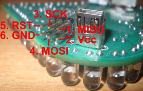
So we make the following connections:
-
ICSP pin 1 onto the ICSP Pin 1 of the Arduino (MISO)
-
ICSP pin 2 onto the ICSP Pin 2 of the Arduino (Vcc)
-
ICSP pin 3 onto the ICSP Pin 3 of the Arduino (SCK)
-
ICSP pin 4 onto the ICSP Pin 4 of the Arduino (MOSI)
-
ICSP pin 5 onto the Arduino Pin used to reset the Microcontroller (in the Arduino Mega is 53, 10 on the others)
-
ICSP pin 6 onto the ICSP Pin 6 of the Arduino (GND)
Coming back to the firmware, let’s start by loading the Arduino sketch “ArduinoISP “which is located in the examples (make sure you choose the right kind of Arduino in the option if you have ever changed), then go to Tools->Programmer and choose “Arduino as ISP”.
Now we need to set the fuses of our ATtiny85 so to work at 8MHz (the factory setting is 1 MHz). To do this we’re going to upload a fake bootloader which, in reality, is only meant to change the settings of the fuses. So let’s go to Tools-> Arduino type and select”ATtiny85@ 8 MHz (internal oscillator; BODdisabled)” and then go to Tools-> Write Bootloader. If everything was done as described, you should see some LEDs blinking and, after a while ‘, the confirmation of the transaction occurred on the IDE.
You are also going to see few errors such as “avrdude: please define PAGEL and BS2 signals in the configuration file for part ATtiny85”, but don’t panic: this kind of errors will be reported every time you program the ATtiny and you can use it as a confirmation that the transaction is successful.
If there is reported some other type of error, you’ve probably done something wrong in the previous steps, then turn off the power to the circuit and verify that the IDE settings and connections are correct.
Now we just have to load the program to the microcontroller and to do so, just open the IDE and without changing anything from the previous process, go to File->Load a programmer. If all goes well it should happen that we described earlier but this time you should only got two errors.
Configuration

We will now see how to modify the program according to our needs. At the beginning there are few parameters. The first is DURATION, which determines the duration of each light effect, in milliseconds. The second and third are I_VIBRATION and D_VIBRATION. These two parameters are used to set the sensitivity to vibration according to the type of vibration switch you are using (some can be more sensitive).
To set the maximum sensitivity, set the first to 0 and the second to 2: this will start the LEDs at the first vibration felt. If you want to reduce the sensitivity, you’ll need to increase the value of the two parameters, for example by putting the first at 180 and the second at 90. Clearly, these values variables depend on the sensitivity of each individual vibration switch.
To assess if you have a very sensitive model or not, you can shake the heartthrob and place it close to your ear, you should hear the movement of the ball inside the switch. If this noise continues for a long time, about more than a second after the end of vibration, then your switch is very sensitive to vibration.
The fourth parameter, NUMBER_OF_FUNCTIONS, is used in case you want to add or remove other lighting effects. In this case you also need to make some changes in lightEffect routine and in particular in the switch, making sure that you have all the cases from 0 to NUMBER_OF_FUNCTIONS-1.
Download all files
Developed by @VicenzaThunders (R. Ertolupi, D. Spreggiaro)
Enjoy your Valentine!

Related Posts


5 Comments
Leave a Reply
-
 Arduino ISP (In System Programming) and stand-alone circuits
We use an Arduino to program other ATmega without...
- Posted 12 years ago
-

-

-
 GSM GPS shield for Arduino
Shield for Arduino designed and based on the module...
- Posted 12 years ago
-
 Small Breakout for SIM900 GSM Module
Some post ago we presented a PCB to mount...
- Posted 13 years ago
-
 Join Maker Faire Rome 2024: Innovation Unleashed at Gazometro Ostiense | Calls Now Open!
All Calls Now Open for Maker Faire Rome 2024...
- Posted 2 weeks ago
-
 Building a 3D Digital Clock with Arduino
Project to create a digital clock consisting...
- Posted 4 months ago
-
 Acoustic amplifier – in DIY Kit
This kit creates a microphone amplifier with an output...
- Posted 5 months ago
-
 Creating a controller for Minecraft with realistic body movements using Arduino
Project of a controller that maps body movements...
- Posted 5 months ago
-

Pingback: Video: Hacking a Valentine with the ATtiny85 | Atmel Bits & Pieces